Note: Descriptions are shown in the official language in which they were submitted.
2 ~ ~6~5 3
POSITIVE TRANSITION OUIC~ K~ PIPING
~ N~ OF T~ lNV~ lON
This application relates to a quick connect fluid
coupling which ensures that a tube is not sealed unless the
tube is fully inserted into a connector structure.
Quick connect fluid couplings are well known in the
art and used to quickly connect a tube to a housing or second
tube. Several quick connect couplings are utilized in most
modern vehicles to connect brake lines, air conditioning
lines, power steering lines and other high pressure lines to
a housing, or second tube.
A particularly successful prior art coupling
consists of a spring or retainer received within a female
housing bore. The retainer has a plurality of arms which
extend radially inwardly in a direction moving axially into
the bore. The tube has a radially greater upset portion
which moves into the bore and abuts an inner peripheral
surface of the arms. The axially and radially innermost ends
of the arms define an inner diameter approximately equal to
the outer diameter of the tube at locations other than the
upset portion. As the tube is inserted further into the
bore, the upset portion forces the arms radially outwardly,
and moves axially past the arms. Once the upset portion has
moved axially beyond the arms, the arms spring back to a
position where they are radially outwardly of the tube, and
axially between the upset portion of the tube an outer end of
the bore. The tube is then fully inserted, and the retainer
securely retains the tube within the housing.
In one prior art coupling, the retainer is of a so-
called "avalanche" type where the force required to insert
the tube into the housing is at a first relatively low point
for initial axial insertion, and then rises sharply to a
relatively high point a~ter the upset portion initially
contacts the inner periphery of the arms. The point where
~,
W094/08172 PCT/US93/09479
~462'S3
_
this high required force begins is defined as an "avalanche~
point. Once an operator has supplied sufficient force to
overcome this high required force, the momentum carries the
tube further axially inwardly and ensures that it is fully
inserted.
Problems are sometimes encountered with this type of
quick connect coupling since a tube inner end is at an axial
position where it is aligned with seals in the housing prior
to reaching the avalanche point. The seals engage the outer
periphery of the tube and provide some resistance to further
insertion of the tube. This may give a false impression or
feel to the assembler that the high required force may have
been overcome. Thus, the prior art has sometimes resulted in
an assembler misinterpreting this feel as an indication that
the tube is fully inserted. Further, if an assembler
neglects to fully insert the tube for whatever reason, it is
still possible that the prior art couplings will provide a
seal between the tube and the housing.
It is undesirable for the tube not to be fully
inserted since it could become disconnected in use. This is
particularly true when the tube is used in a vehicle. With
the prior art structure discussed above, should the tube not
be fully inserted within the housing, a seal may still be
provided between the housing and the tube. The seal may be
adequate for a period of time until the vehicle has driven
off the assembly line and away from the factory. The fluid
pressure in the line, vibration or temperature cycling, will
eventually cause the tube to become disconnected from the
housing. It is far more preferable for the improper
connection to be identified before the vehicle leaves the
assembly line.
SUMMARY OF T~8 INVENTION
In one disclosed embodiment a quick connect fluid
coupling does not provide a seal between a tube and a housing
until the tube has moved beyond a point where it will be
fully inserted. In one disclosed embodiment, a required tube
SUBSTIT~JTE Sl {EET (~)LE 26~
WO94/08172 2 1 4 6 2 5 3 PCT/US93/09479
insertion force begins at a low level, then increases sharply
to a relatively high level at a first axial position. Once
this relatively high level of force is overcome, momentum
carries the tube to its fully inserted position. The axially
innermost end of the tube is not received within a seal in
the housing until the tube passes this first axial position.
Thus, no false feel is given to an operator that the tube is
fully inserted. Moreover, if the tube is not fully inserted
there is no seal. If the vehicle is moved off of an
assembly line, the high pressure fluid will noticeably leak.
The tube preferably has a radially greater upset
portion spaced from an inner axial end. The retainer
preferably has a number of resilient arms which extend
radially inwardly from an outer end of the bore axially into
the bore. The tube is inserted until the upset end initially
contacts an inner peripheral surface of these arms. This
initial insertion is the low level required force discussed
above. This point is the first axial position, or avalanche
point. Further insertion of the tube requires the upset
portion to bias the arms radially outward, which requires the
sharply increased tube insertion force.
As the tube moves beyond the avalanche point, the
upset portion of the tube begins to bias the arms radially
outwardly. The axially innermost end of the tube may then
move into a first seal. As noted above, once this avalanche
point is passed, the momentum of the tube carries it to its
fully assembled position. Thus, it is desirable that the
seal begin contacting the tube soon after the avalanche point
is passed.
Further, any resistance to the tube insertion from
the seal will occur within the area where the sharply
increased force is provided. Thus, the resistance from the
seal will be easily overcome, and will not provide a false
feel to an operator.
In a most preferred embodiment of the present
invention, the axially innermost end of the tube is adjacent
to the axially outermost end of a first seal when the tube
~U8S~T'~ U~E 26)
WO94/08172 6~5~ ~ PCT/US93/09479
reaches this avalanche point. This preferred alignment of
the seal and axial end of the tube results in the greatest
amount of sealing possible, while still not providing a seal
until the tube is fully in~serted.
In a second embodiment, the tube has two stepped
diameters positioned inwardly from the upset portion. Seals
are positioned within the housing and associated with each of
these two stepped portions. An axially outer seal is
positioned radially outwardly from the radial position of an
axially inner seal. The two stepped tube includes an inner
portion which is radially smaller than an outer or body
portion positioned between the inner portion and the upset
portion.
When the tube is inserted into the housing and the
upset portion initially contacts the retainer, the inner
portion may be axially aligned with the outer seal, which is
adapted to contact the outer portion. This seal will not
sealingly engage the inner portion, however, as it is
positioned radially outwardly from the outer peripheral
service of the inner portion. Thus, no seal will be made at
that position.
Once the tube moves further in, and the upset
portion deforms the resilient arms radially outwardly, the
inner portion of the tube will sealingly engage the axially
inner seal. Further, the body portion of the tube will
sealingly engage the outer seal. Thus, due to the unique
construction of the tube and the positioning of the seals,
two good seals are obtained after the relatively short axial
movement. This may sometimes provide advantages over the
first disclosed embodiment wherein the tube inner end must
generally move through a longer axial length.
These and other objects and features of the present
invention can be best understood from the following
specification and drawings, of which the following is a brief
description.
SU8STI~U~~ ~ ~E~ ~PILU!E 26)
WO94/08172 2 l ~ ~ ~ 5 3 PCT/US93/09479
"_
~RIEF nR-e~PTPTION OF T~E DRAWINGS
Figure l is an exploded perspective view of a
construction embodying a first embodiment of the present
invention .
Figure 2 is a cross-sectional view of a portion of
the construction shown in Figure l.
Figure 3 is a cross-sectional view of the
construction shown in Figure l.
Figure 4 is a view similar to Figure 3.
Figure 5 is a view similar to Figure 4.
Figure 6 is a view similar to Figure 5.
Figure 7 is a cross-sectional view of a second
embodiment of this invention.
Figure 8 is a view similar to Figure 7.
Figure 9 is a view similar to Figure 7.
Figure l0 is a view similar to Figure 7.
Figure ll is a cross-sectional view of a portion of
the construction shown in Figure 7.
DB~TT~n nR-5~TPTION OF A rn~r-~nn~v BMBODIM~NT
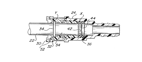
Figure l discloses a quick connect fluid coupling 20
for connecting a tube 22 within a housing 24. Housing 24 has
structure 26 at a downstream end to be connected to a
downstream tube 28.
A retainer 30 is inserted within housing 24 and
includes a plurality of arms 32 which extend radially
inwardly to abut an upset portion 34 of tube 22. Upset
portion 34 is of a greater radial outer diameter than
portions on either axial side of upset portion 34. An inner
tube end 36 extends through an opening 38 in retainer 32,
through spacer 40, and sealing engages O-ring seals 42 and 44
to provide a fluid tight seal between tube 22 and housing 24.
As shown in Figure 2, retainer 30 is inserted within
bore 46 in housing 24. Bushing 40 and O-rings 42 and 44 are
positioned in bore 46 axially inwardly of retainer 30.
S~J~STlf~3~ S~EET ~ E 26)
W094/08172 PCT/US93/09479
2~6~5~
As shown in Figure 3, coupling 20 is assembled by
inserting tube 22 into bore 46. Inner end 36 will eventually
sealingly engage seals 42 and 44.
As shown in Figure 4, tube 22 may be easily inserted
into bore 46 until upset portion 34 initially contacts an
inner peripheral surface of an arm 32. An outermost 0-ring
42 is centered at a first axial position x. The location y
on the inner periphery of arms 32 which upset portion 34
initially contacts is defined as a second axial position.
The distance x-y between the first and second axial positions
is greater than the distance between upset portion 34 and
inner end 36 of tube 22. Thus, when upset portion 34
initially contacts the inner peripheral surface of arms 32,
inner end 36 does not sealingly engage the outermost seal 42.
At this point there is no seal provided between tube 22 and
housing 24.
The point where upset portion 34 reaches second
axial position y is known as the avalanche point. Up to this
point the insertion force was low, it will not increase
sharply.
As tube 22 continues to be inserted, upset portion
34 begins to bend arms 32 radially outwardly. This is known
as the positive transition zone and is illustrated in Figure
5. A sharply increased force is required over the force
required to insert tube 22 to the position shown in Figure 4.
As upset portion 34 is biasing arms 32 radially outwardly,
inner end 36 of tube 22 begins to move within O-rings 42 and
44 and is sealingly engaged within housing 24.
Thus, as tube 22 is moving through the positive
transition zone where the sharply increased force is required
inner end 36 is also being forced into seals 42 and 44. Any
resistance to insertion of tube 22 from seals 42 and 44 will
occur during this sharply increased force zone, and thus the
resistance by the seals will not provide any false feel to an
assembler.
As shown in Figure 5, a first radially inwardly
inclined surface 52 is formed on arms 32 and extends to a
T~T~ T ~s5 ~ ~ 2~
WO94/08172 PCT/US93/09479
2l46253
,. ,. ,~
second surface 54 which is formed at an angle generally
parallel to the axis of the bore. Once upset portion 34
reaches the apex between portions 52 and 54, the force
resisting insertion of tube 22 decreases rapidly. Upset
portion 34 then snaps beyond second inclined portion 54 into
a fully inserted position.
The force required to move tube 22 beyond the
initial avalanche point, such as shown in Figure 4, and
through the positive transition zone, shown in Figure 5,
carries tube 22 to its fully inserted position shown in
Figure 6. Tube 22 is now fully inserted into housing bore
46. Upset portion 34 is received axially inwardly of an
axially innermost end of arms 32. Tube 22 is securely
retained within housing 24. Moreover, the axially inner end
36 of tube 22 is received radially inwardly of seals 42 and
44 providing a fluid tight seal.
As illustrated in Figures 4 and 5, when tube 22 has
upset portion 34 at the second axial position y, or avalanche
point, inner end 36 is spaced slightly from seals 42. Inner
end 36 is beveled, and a portion of its beveled surface is
axially aligned with an axially outer portion of outermost
seal 42. Seal 42 is still spaced radially from inner end 36.
Once upset portion 34 begins to bias arms 32
radially outwardly into the positive transition zone, as
shown in Figure 5, inner end 36 immediately contacts the
outermost seal 42. As shown in Figure 6, once fully inserted
inner end 36 is spaced axially inwardly from the outermost
seal 42 by the maximum distance that still provides no seal
until upset portion 34 moves into the positive transition
zone.
Referring now to Figures 7-ll, there is shown a
~ quick connect tubing connector assembly 60 made in accordance
with the teachings of a second embodiment of this invention.
Specifically, assembly 60 includes a tube 62 having a beveled
end 63 adjacent an inner portion 64 of a relatively small
diameter and a body portion 66 of a relatively large
diameter. As further shown, an upset portion 68 having a
~U~ TU ~ ~ ~Y,~ lJLE 26)
WO94/08172 PCT/US93/09479
~6~3 _~
diameter greater than either the diameter of body portion 66
or inner portion 64 is positioned outwardly of body portion
66. Upset portion 68 is spaced a predetermined distance 70
from inner portion 64.
As further shown, assembly 60 includes housing 24
and retainer 30, including a plurality of resilient arms 32.
As previously described, housing 24 provides a bore 46 having
an opening 72, adapted to receive and secure tube 62 within
bore 46. An inner seal 74 is positioned axially and radially
inwardly from an outer seal 76. Inner seal 74 and outer seal
76 are both received in housing 24, with inner seal being
thicker than thinner outer seal 76.
As shown in Figure 7, with the tube 62 initially
inserted, inner portion 64 is axially aligned with outer seal
76. Outer seal 76 does not contact inner portion 64, and
thus no seal is provided at this point. This position
corresponds to the avalanche point. Once upset portion 68
begins to bias arms 32 radially outwardly, as shown in Figure
8, inner portion 64 begins to contact inner seal 74 and body
portion 66 begins to contact outer seal 76. As further shown
in Figure 9, upon further insertion of tube 62 the seals are
fully made on tube 62. Figure l0 shows the connector after
application of fluid pressure.
With the inventive arrangement of the two stepped
tube 62, and the positioning of seal 74 and 76, one ensures
that the seals are disposed axially upwardly far enough on
the outer peripheral surface of tube 62, while still not
requiring a great deal of tube travel past the avalanche
point shown in Figure 7. It is sometimes desirable to
minimize the total movement between the avalanche point such
as shown in Figure 7, and the fully connected position such
as shown in Figures 9 and l0. Further, it is sometimes
desirable to ensure that the seals are positioned axially far
upwardly along the outer peripheral surface of tube 62. The
unique arrangement of the two stepped tube end provides both
benefits.
SU~ST~iU~E5~ ~T~F~U~ ~26~
CA 021462~3 1998-09-03
As shown in Figure 11, tube 62 includes two stepped
portions including inner portion 64 and body portion 66, with
a distance 70 defined between the axially outer end of inner
portion 64 and the axially inner end of upset portion 68.
Preferred embodiments of the present invention have
been disclosed, however, a worker of ordinary skill in the
art would recognize that certain modification~ would come
within the scope of this invention. Thus, the following
claims should be studied in order to determine the true scope
and content of the invention.