Note: Descriptions are shown in the official language in which they were submitted.
~ WO 94/08494 2 ~ ~6 3 3 4 Pcr/Nog3/oo154
ARRA~;~N-l IN A ~UKN~ ;K, ~ AT-T.y A LEG ~U~Kll
The area of the Invention
The present invention relates to an arrangement in a calf-
supporting part for a piece of furniture or such like,
particularly a chair, comprising a chair seat part and a back
rest part, the calf-supporting part comprising a web-shaped
portion which is given support by means of moveable support-
ing/carrying devices and runs in a loop through one or severalcurved guides attached to the supporting/carrying devices, so
that the web-shaped portion may be pushed continuously between
a shielded, inactive retracted position beneath the chair seat
portion and an active protruding calf-supporting position,
chiefly flush with the chair seat part.
Prior Art
From NO patent specification 162.994 a chair arrangement is
known of the nature stated above, a calf-supporting part
having been made of an upholstered web-shaped portion,
stiffened in its traverse direction, the said web-shaped
portion consisting of a base of traversing stays, comparative-
ly rigid in their lengthwise direction and sideways interlink-
ing. Above the said stays, upholstery is arranged, and also aweb-shaped cover material, preferably a cover material
matching the cover of the chair as such.
The background to the present invention is in the task of
showing an improved arrangement in a calf-supporting part in
which there is no need to rely on linked rigid stays for
stiffening the upholstered web-shaped portion, such interlink-
ing, rigid stays being complicated and costly to make while at
the ~ame time the rigidity of the stays causes the rolling
function to be slow-moving.
W094/08494 2~ ~B3~ 2 PCT/N093/0015 ~
A further task of the present invention is in describing an
arrangement which not only avoids the use of interlinking
rigid stays but may also be manufactured from uncomplicated
components, while at the same time the transition of the
calf-support from its passive to its active position and
vice versa may be performed with the use of comparatively
little effort.
nes~r;pt, ~n of the T~v~nt;on
The aims outlined above will be achieved with an arrange-
ment of the nature mentioned initially, which is, according
to the present invention characterised by the supporting /
carrying devices ~ LI~I ising one single slim sheet-shaped
device segregated physically from the web-shaped portion.
Because this physical segregation is achieved between the
actual su~oLLing / carrying devices and the web-shaped
portion, the web-shaped portion may chiefly in itself com-
prise a separate cover material, i.e. a material or man-
made or cloth-like structure constituting the same cover
material or readily adaptable to the cover material of the
piece of furniture, specifically the chair seat.
Preferably, the sheet-shaped supporting/carrying device is
at either side of its rear part fitted with a smooth wheel
and a toothed wheel. Preferably then each of the toothed
wheels on the sheet-shaped supporting/carrying device will
interact with a corresponding toothed track or toothed
guide each arranged in a groove positioned at the side and
fastened to the underside of the chair seat or to other
parts of the chair or the piece of furniture.
At its forward part, the sheet-shaped supporting/carrying
device may then have been made with a guide designed as a
smooth sliding roller, which runs traversely and can be
turned freely.
334
W094/0~94 3 PCT/NO93/00154
At the rear area of the sheet-shaped supporting/carrying
device a transverse turning axle is arranged, carrying
ateither end one each of the said toothed wheels, in order
thereby to turn in step with these while at the same time
at least one band-like guiding device has been wound round
the said turning axle.
The said band-like guiding device is at its one end fixed
permanently to a frame part, chiefly arranged at a lower
forward part of the chair seat part, in which area also one
stationary traversing edge of the web-shaped portion has
been attached, the band-like guiding device at its other
end being fixed to the opposite moveable traversing edge of
the web-shaped portion.
From a retracted passive position below or behind the rele-
vant part of the chair, in particular the chair seat part,
the calf-supporting part may th~seby be pushed forward,
namely by the sheet-shaped supporting/carrying device being
pushed forward, e.g. by means of a handle arranged at the
forward smooth sliding roller. This sliding roller will
then, being in contact with the underside of the web-shaped
portion, push the said web-shaped portion ahead while at
the same time the proportions of the web-shaped portion
pushed out will make contact with the slim sheet-shaped
supporting/carrying device.
The movable traverse edge of the web-shaped portion is held
taughtly in place below the sheet-shaped supporting /
carrying device by means of the said band-like guiding
device both when being parked underneath the chair seat
part, while the supporting/carrying device is being pushed
out, and even when in particular the calf-support is fully
extended in its calf-supporting position.
It should be understood that the present invention has been
developed especially in connection with a calf-supporting
part for a chair, but the present su~porting/carrying
device may also find a use in connection with chair backs
W094/08494 21 4 ~ PCT/NO93/00154 -
to possibly adjust the height and the shape of the chair
back, and in particular together with an adjustable calf-
support. Such an adjustment of both back and seat will en-
tail that the chair may be adapted to the body size of
individual users, and their purpose of use, which could be
appropriate for chairs in the home, on trains, in aircraft,
as well as in other means of transport and installations.
It should further be understood that the present arrange-
ment may also find a use in connection with furniture other
than chairs, e.g. beds, which may have their width, length
or resting area extended in a simple and energy-conserving
manner. The device may e.g. be executed as an attarhm~nt
to a sofa-bed, or as a sideflap to a hospital bed.
Additional features and advantages will be seen from the
description below, taken in conjuncture with the attached
drawings.
Rr;ef neScr;ption of F;~res in t~e nr~wi~gs
Figure l is a schematic outline perspective of a calf-sup-
porting part for a chair comprising a chair seat part and a
back part, the calf-supporting part being shown here in its
retracted position below the chair seat part.
Figure 2 is a schematic outline perspective like figure l,
showing the calf-support in its protruding calf-supporting
position in front of the chair seat part.
Figure 3 is a schematic blown-up outline perspective of an
embodiment of a supporting/carrying device according to the
present invention.
Figure 4 is a cut-out of an outline viewed from above of a
correspo~ing embodiment for the supporting/carrying device
according to the present invention.
Figure 5 is a section along the line V-V of figure 4.
~6~
W 0 94/08494 5 PC~r/N 093/00154
Figure 6 is a supplementary cut-out of the outline shown in
figure 4, showing an embodiment for a supporting/carrying
device according to the invention.
Figure 7 is a sideways outline of the embodiment for a sup-
porting / carrying device shown in figures 4-6.
Figure 8 is an outline viewed from above of an em.bodiment
for a supporting / carrying device according to the inven-
tion, fitted into yrooves or profiles placed at the sides,the fully drawn line showing the supporting / carrying
device when the calf-support is retracted, while the broken
lines show the device in its protruding calf-supporting
position.
Figure 9 is an end-on outline of the em.bodiment shown in
figure 8.
Figure 10 is a sideways outline of the em.bodiment shown in
figure 8, with some components shown when the supporting /
carrying device is in its retracted and its protracted
position, respectively.
Figure 11 illustrates some components of the supporting /
carrying device in its protruding position.
Figure 12 shows schematically details of the embodiment in
grooves or profiles of the supporting / carrying device
according to the invention.
Figure 13 is an outline, s~m; l~r to figure 8, with further
components of the calf-support included in the drawing.
Figure 14 shows a sideways outline of the embodiment
according to figure 10, here with an adapted cut-out of the
chair seat part and the contacting web-shaped portion of
the calf-supporting part in its retracted position.
Figure 15 shows a corresponding sideways outline as figure
14, but with the calf-supporting part and the web-shaped
W 0 94/08494 ~ 33 ~ ~ PC~r/N 093/00154
portion in its protruding calf-supporting position.
Det~1led Description of ~mho~ nts
Shown in outline in figures 1 and 2 is a chair upper of a
chair generally defined by the reference numeral 1.
The chair 1 is covered in a web-shaped material 2, the said
material covering a chair back part 3 and a chair seat part
4. The chair 1 also comprises a calf-supporting part
defined here by the reference numeral 5 which may be pushed
continuously between a shielded inactive retracted position
n~rn~th the chair seat part 4, as is evident from figure
1, and an active protruding calf-supporting position,
chiefly flush with the chair seat part 4, as will be
evident from figure 2.
It should be understood that the chair 1 may also be
executed with a corresponding back supporting part which
may be pushed continuously up and down flush with the chair
back part 3 of the chair.
The calf-supporting part 5 comprises a main part which is
chiefly in the form of a web-shaped portion running from
its forward edge 4a of the chair seat part 4, in a loop 4b
through suitable curved guides which will be mentioned
later and are attached to suitable supporting/carrying
devices also to be mentioned later. The web-shaped portion
5 is of a length corresponding approximately to the fully
protracted calf-supporting part as is evident from figure
2, and thus stretches from a forward traversing edge 5a
arranged by or incorporated in the forward portion 4a of
the chair seat part 4, to a rear traversing edge 5b.
Shown in figures 3-7 is a particular embodiment for the
moveable supporting/carrying devices which support the web-
shaped portion 5 mentioned above, and also comprising
suitable guiding devices.
W094/08494 7 ~ 3~ ~ PCT/NO93/00154
.. ..
Thus, the said supporting / carrying devices of the
embodiment shown in figures 3-7 are executed as one single
slim sheet-shaped device 6, capable, because of its expanse
lengthwise and across, of supporting the web-shaped portion
5 shown in figures 1 and 2 without being an integrated part
of the web-shaped portion. In other words, the sheet-
shaped portion 6 may be fashioned physically separate from
the said web-shaped portion 5 which ~nt~;lS a number of
advantages which will be mentioned below.
Firstly, the web-shaped portion, because of the sheet-
shaped supporting/carrying device may be executed chiefly
as a separate cover material, i.e. of a material, man-made
or cloth-like structure which makes up the same cover
material or is readily adaptable both to the cover material
of the chair seat part 4 and the cover of the back part 3.
The sheet-shaped supporting/carrying device 6 is as shown
in figure 5 made with longitll~;n~l ribs 7a and 7b, and at
the rear portion 6a of the sheet-shaped supporting/carrying
device 6 a bracket 8a and 8b, respectively, is screwed into
the said ribs, preferably by means of suitable screw and
bolt connections 9. A portion of the said brackets, 8a,
8b, protrude over the rear portion 6a of the supporting /
carrying device 6 in order there to carry a smooth wheel,
lOa and lOb, respectively, and a toothed wheel, lla and
llb, respectively. Between the said toothed wheels, lla
and llb a traversing rotating axle extends which turns
together with the said toothed wheels, while at the same
time two guide reels, 13a and 13b, respectively, are
arranged on the axle. These guide reels 13a and 13b may
turn more or less freely on the said axle 12, but with a
suitable small play, and the said guiding reels 13a and 13b
serve to guide one each of the band-like guiding devices
which will be mentioned in further detail below.
At its forward portion 6b on the ribs 7a, 7b a guiding
device is arranged, designed as a chiefly smooth sliding
roller 14, freely rotatable and running transversely,
W094/08494 2~ ~334 8 PCT/NO93/0015 0
suitably held by roller bearings 15 which are in turn
suitably fixed by means of screws 15a, 15b.
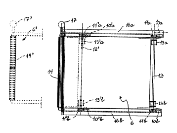
Shown in figures 8-12 is how the sheet-shaped supporting /
carrying device 6 mentioned above may be mounted into
suitable guide rails or profiles which may be attached to
the underside of the chair seat part 4, or some other
suitable stationary part of the chair frame.
Shown in the said figures are thus two sideways positioned
grooves, 16a and 16b, respectively, the cut-out of these
grooves 16a and 16b being shown to a larger scale in figure
12. As will be seen from the latter figure 12, in each of
the grooves a toothed track or toothed guide 17 has been
arranged in which the said toothed wheels 11a, llb engage
while at the same time the pert~tn;ng smooth wheel, lOa and
lOb, respectively will make contact with a groove portion
19 which is opposite to the groove portion 20 carrying the
respective toothed tracks or guides 17.
Shown in figure 8 is an outline viewed from above of the
previously mentioned supporting/carrying device 6 when
mounted into the sideways positioned grooves 16a, 16b, the
fully drawn line showing the supporting/carrying device 6
with the calf-support retracted, while the broken line
shows how the supporting/carrying device 6' with its
forward smooth sliding roller 14' and its traversing axle
12~ with its toothed wheels, llla and ll~b, respectively,
and smooth wheels, lO'a and lO~b, respectively, and the
guide reels 13'a and 13'b, has been pushed left in the
figure, namely along and partly out of the stationary
grooves 16a, 16b.
Because of the interrelationship between the toothed wheels
lla, llb and the smooth wheels lOa, lOb, please see in
particular figure 12, the sheet-shaped supporting/carrying
device 6 can be moved between a retracted position under
the chair seat part 4 and to a protruding calf-supporting
position in an effortless yet well controlled m~nn~r. It
3 ~ ~
W094/08494 9 PCT/NO93/00154
should be understood that moving the sheet-shaped
supporting / carrying device 6 back and forward may be done
by means of a knob 17 fitted and protruding from the side
in line with the centre axis of the said smooth sliding
roller 14, please see figure 8.
From figures 9, 10, 11 it is evident that the grooves 16a
and 16b are fashioned as curves which Pnt~;ls that also the
sheet-shaped device 6 is of a corresponding shape, curved
in its lengthwise direction. It should, however, be under-
stood that the curvature which may be given to the sheet-
shaped device 6 as well as the grooves 16a and 16b, may
vary within wide limits, since this may be adapted to the
relevant design of the actual calf-supporting part and the
chair concerned on which the calf-support~ng part is to be
fitted.
A comparison of figures 9, 10 and 11 shows that the sheet-
shaped ~u~oLLing/carrying device 6 follows a curved path
when being pushed between its retracted position and its
protruding cal~-supporting position, a ~act which is also
shown here in full and broken lines respectively.
Shown in figures 13-15 are two band-like guiding devices,
20a and 20b, respectively, which at one end, 21a and 21b,
respectively, are ~astened to e.g. a stationary crossbar 22
between the two grooves 16a, 16b, and carried in parallel
along the top of the sheet-shaped device 6 and each via its
guide reel on the transverse main axle 12, the reels 13a
and 13b, respectively, in order at their opposite ends, 22a
and 22b, respectively, to be attached to the internal,
moveable traverse edge 5b, please see figure 1, of the web-
shaped portion 5.
v
The web-shaped portion 5 may in turn have its second
forward t~dveLse edge 5a fastened in the area of the said
stationary crossbar 22, or be otherwise attached in order
chiefly to be flush with the chair seat part 4.
3 3 ll
W094/08494 10 PCT/NO93/0015
It should be understood that the said grooves 16a, 16b at
their rear edges may be held together by means of a second
crossbar 23, which entails that the sheet-shaped
supporting / carrying device 6 with its pert~in;ng grooves
16a, 16b, may be designed as a one-part bracket-frame,
defined here by the reference numeral 24, which may be
adapted to factory fitting or subsequent fitting on the
chair concerned.
It should thus be understood that when the calf-support,
comprising the web-shaped portion 5, is pushed forward from
the position shown in figure 1 to the position shown in
figure 2, this ..I~v~..ellL takes place in the emboA;m~nt
mentioned above, in particular by means of the knob 17, and
the transfer of force then takes place through the smooth
sliding roller 14 which cn~mln;cates directly with the
underside of the web-shaped portion 5 to push it forward,
while at the same time ever larger zones or proportions of
the sheet-shaped supporting/carrying device 6 will support
the said web-shaped portion 5. When the foot-rest 5 is
pushed backwards, the knob 17 will be forced backwards, the
force then being transferred to the sheet-shaped supporting
/ carrying device 6, while at the same time the parallel
guide bands 20a, 20b, pull the rear moveable traverse edge
5b of the web-shaped portion 5 backwards to its shielded,
inactive position under the chair seat part, while at the
same time the said guide bands 20a, 20b, optionally by
means of suitable additional devices, keep the said
tranverse edge 5b and the web.shaped portion 5 as such well
concealed underneath the chair seat part 4.
Such ret~ n; ng devices are shown in figure 14 by the
reference numeral 30 and may e.g. comprise a spring-loaded
board or a multitude of springy fingers which with a rear
portion are fixed to a corresponding rear portion of the
supporting/carrying device 6 or a rear portion of the said
bracket-frame 24.
21~633~
W094/08494 11 PCT/N093/00154
In order further to achieve a tight guiding of the band-
like guiding devices 2Oa and 2Ob, these may be executed
with suitable elasticity, and/or tracks or indentations
(not shown) may be fashioned in the actual surface of the
sheet-shaped device 6, in order that the bands 2Oa and 2Ob
may be given a run as straight and tauyht as possible along
the grooves.
It shall furthermore be understood that in the ~luoves 16a,
16b placed along the sides of the bracket-frame 24, straps
(not shown) may be arranged which serve to guide the device
6 and determ;ne how far the sheet-shaped device 6 can be
pulled out of the bracket-frame 24 in its fully protruding
position.
The device according to the invention is here described in
connection with a chair, in particular a reclining rest for
a chair, but it shall be understood that the device may
also be used in general in furniture and in seating and
resting bases for users of different sizes and different
seating/resting needs.