Note: Descriptions are shown in the official language in which they were submitted.
- 21~C37~
DIFFERENTIAL PRESSURE SWITCH WIT~ AN ADJUSTING PISTON DRIVEN
BY A RESTORING SPRING FOR AN OIL-SEPARATING AIR FILTER
Background of the Invention
The wide range of applications in the pressure
measurement field has led to the development of many
different types of pressure sensors which utilize a variety
of physical sensing principles (mechanical, inductive,
capacitive, etc.) and embody a large number of constructive
solutions.
Pressure is defined as force per surface by means of
the unit 1 bar = 1*10 N/m = 1*10 pascal. The zero point of
a pressure scale is either the pressure of an absolute
vacuum or atmospheric pressure.
A distinction is therefore made between the
- absolute pressure: ~ vacuum (0 bar) is the
reference point;
- overpressure/underpressure: atmospheric pressure of
approximately 1 bar is the reference point, and S bar
overpressure therefore corresponds to an absolute pressure
of approximately 6 bar.
- differential pressure: indicated by the difference
between two pressures measured in the same reference system.
Accordingly, pressure sensors can be divided into
absolute-pressure sensors, overpressure/underpressure
sensors and differential-pressure sensors. Differential
pressure sensors measure the difference of the pressures
sensed in two separate chambers.
21~6378
In absolute-pressure sensors one of the two chambers is
evacuated so that the measured pressure corresponds to the
absolute pressure.
Overpressure and underpressure sensors require only one
pressure chamber since the comparison takes place with
respect to the external atmospheric pressure. Sensors of
this type can therefore be implemented more easily than the
other two types of sensors.
Because of the vacuum chamber, absolute pressure
sensors are very costly to manufacture.
In addition to being a function of the type of sensing,
the cost of producing a pressure sensor also depends on the
precision, the measuring tolerance and the magnitude of the
pressure to be measured.
Because they are simpler to produce, there are numerous
overpressure and underpressure sensors. They are used where
the measurement can be made with reference to the
atmosphere, as, for example, for determining the degree of
contamination of air and oil filters in vehicles.
In course of use, filters will become increasingly
dirty. This results in an increase of the pressure drop
between the dirty side (in front of the element) and the
clean side (behind the element). When the pressure drop
becomes too large, the filter element has to be replaced.
On the other hand, it can be quite difficult to
determine the pressure drop of filter elements in hydraulic
and pneumatic systems. Since, depending on the system,
different operating pressures will exist here, the
measurement cannot be made with reference to the atmosphere;
instead the differential pressure must be sensed. The high
operating pressures present another difficulty. This is
because the high operating pressures make it very difficult
to establish a connection from the pressure chambers to the
outside.
There are basically three types of filter maintenance
transducers or sensors:
2146378
1. Maintenance indicator (optical)
2. Maintenance switch (electric)
3. Combination maintenance switch/indicator.
Depending on the type of switching, the switches are
divided into break contact switches, make contact switches
and change-over contact switches.
Switch arrangements comprising a piston and a restoring
spring are known. However, because the piston must always
have a certain play in order to move, such switches are
subject to the problem that a short circuit or bypass may
occur around the piston. The medium can therefore
circumvent the filter element and pass directly from the
dirty side to the clean side.
In a hydraulic system, this is not so critical. In
systems in which super-clean air is to be produced by means
of an oil-separating air filter, this may drastically impair
the efficiency of the filter.
In order to permit movement while maintaining a
simultaneous seal, pistons are therefore frequently used in
conjunction with membranes.
However, the conventional membranes usually allow only
small strokes. Therefore, rubber bellows were frequently
used for sealing which, however, cause an undefinable power
shift of the pressure, which makes it difficult to achieve
reproducible pressure sensing.
In oil-separating air cleaner elements, it is also
insufficient to use a piston in combination with O-rings as
a moving seal.
In contrast, a rolling membrane, as a special form of
membrane, permits a relatively large stroke with a
reproducible stroke movement and a minimum housing diameter.
Summary of the Invention
It is therefore an object of the invention to provide
an improved differential pressure switch and/or indicator
with an adjusting cylinder driven by a restoring spring.
21~6378
It is also an object of the invention to provide a differential ~,es~we switch
and/or indicator which has a modular constTuction.
Another object of the invention is to provide a dirrelel~lial ple~ iW~ switch
and/or indicator which can be readily assembled.
S A further object of the invention is to provide a differential pre;,~w~ switch
and/or indicator which is reasonable in cost.
An additional object of the invention is to-provide a dirr~lelllial ples~w~e
switch and/or indicator which can with.~t~nll high ples~iweS.
Yet another object of the invention is to provide a diLrerelllial pl`es~we
switch and/or indicator which has relatively small ~limen~ions.
These and other objects of the invention are achieved by providing a
diLrelc;,llial pres~we indicator compri~ing a piston exposed to ples~ulcs of t~vo
dirre,e,~l pres~w~e zones, wherein said piston is movable in response to a relative
change in ple.,~we bctwt;ell said two pres~w~e zones and is biased in one direction
by a restoring spring, and wherein said dirrer~ pres~we zones are separated by
a rolling membrane.
The invention has particuwar application in the case of oil-s~a,dlillg air
cleaner elements, because the dirrele.,l plei,~ule zones are separate by means of a
rolling membrane.
Advantageous pl~er~"ed embo-liment~ are described hereinafter. These and
other fedlules of prere". d embofliment~ of the invention, in additional to being set
forth in the claims, are also disclosed in the specification and/or the drawings, and
the individual features each may be implementecl in embo~liment~ of the invention
either individually or in the form of subcombinations of two or more redlwes andcan be applied to other fields of use and may con~lilul~ advantageous, separately
ldble constructions for which protection is also claimed.
Brief Desc,;~tion of the Drawin~s
The invention will be described in further detail hereinafter with reference
to illu~lldlive prc;r~"ed embodiments shown in the acco~ ~lying drawings in
which
- 4 -
- ~ 2146378
Figure 1 is a view of a maintenance indicator;
Figure 2 is a view of a maintenance switch; and
Figure 3 is a view of an indicator switch.
Detailed Description of Preferred Embodiments
All three possible types of maintenance sensors were
developed as modular plug-in type or snap-mount type
devices. This means that all three types have the same
basic modular structure.
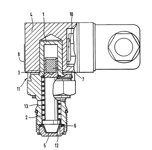
In the indicator embodiment, a æwitching and/or
indicating part 4 with a transparent indicating area 8 and
a pressure scale is snapped onto the basic body or cylinder
housing 1 of the adjusting piston. In the switch
embodiment, a switch housing is snapped onto the cylinder
housing of the adjusting piston. In the switch/indicator
embodiment, a switching and indicating part 4 with a
transparent indicating area 8 and a pressure scale and an
integrated switch is snapped onto the cylinder housing 1.
The differential pressure acts upon a rolling membrane
with a piston. A restoring spring 2, which is integrated
- into the housing, serves as a restoring force or
counterforce. A very small rolling membrane 5 is integrated
in the cap screw (M 18 x 1.5). In addition, this rolling
membrane 5 is reinforced by woven fabric, and as a result
the device is able to withstand differential pressures of up
to 8 bar.
As a rule, rolling membranes 5 are provided with an
injection-molded reinforcing rib. However, this is not
possible in the case of this small rolling membrane because
it has a thickness of only 0.18 mm. In this process, the
membrane is deep-drawn from membrane material and stamped
out. The rolling membrane 5 the rolling membrane is mounted
in a force-locking manner and is clamped tightly in place by
means of an interposed O-ring 6. The rolling membrane 5 is
inserted in a bushing with the O-ring. The cylinder housing
1 of the adjusting piston is preferably provided with two
2146378
bores 12 for tapping or sensing the pressure of the-dirty
side. The interior form is conical in shape corresponding
to the angle of the rolling membrane 5 and of the end of the
adjusting piston. This assures an optimal rolling motion
and simultaneously serves as a guide for the piston/membrane
system during assembly.
The arrangement of the bushing/O-ring/membrane/
piston/piston guide in the cap screw is such that, when the
pressure increases, the sealing effect is increased by the
deformation of the O-ring in the sealing gap. In addition,
the housing diameter on which the rolling membrane unrolls
always rem~; ns the same.
The basic component is assembled as follows: First,
the ~ar magnet 7 is fixed in the piston 3 by gluing/crimping
it in place. The O-ring 6 is pressed into the bushing, and
the rolling membrane 5 is inserted into the bushing. The
pressure spring 2 is placed over the adjusting piston 3.
The adjusting piston 3 wlth the restoring spring 2 is now
fitted with its conical bottom end in the conical
membrane/bush opening and introduced into the cap screw
closure thread. The bushing is pressed against a stop and
is optionally secured in place against the cap screw by
crimping a flanged lower edge.
So that no bypass can occur through the thread of the
cap screw, an O-ring 6 is mounted in a recess of the cap
screw. An aluminum sealing ring is pushed over the thread.
The O-ring is mounted on the thread recess of the locking
screw by means of a mounting mandrel.
In the maintenance indicator embodiment shown in Figure
1, the annular magnet 9 is fitted in place and a switching
and/or indicating part 4 with a transparent indicating area
8 ic snapped on. In the maintenance indicator, the annular
magnet 9 is used as an indicator element and, in the
switch/indicator the magnet is used simultaneously as a
switching magnet.
2146378
In the switch embodiment, the magnetic region 7 ~f the
adjusting piston directly switches on the reed contact 10.
The reed contact 10 is bent, glued into the switch housing
and connected to a plug connector with a socket (Protective
System IP 65). A change-over reed contact is used which can
carry out all types of switching (break contacts, make
contacts and change-over contacts). Optionally, a pure make
contact variant may be used with the same mounting
measurements which saves mounting, fabricating and
purchasing costs in comparison to a change-over contact.
The pressure tap or pressure sensing on the clean side
(lower pressure) behind the filter element occurs through a
bore 13 located between the recess for receiving the snap
connector detent and the mounting thread for receiving the
cap screw.
The reinforcement or amplification of the clamping
force of the membrane when the pressure increases, takes
place by means of the clamping system/arrangement.
The foregoing description and examples have been set
forth merely to illustrate the invention and are not
intended to be limiting. Since modifications of the
described embodiments incorporating the spirit and substance
of the invention may occur to persons skilled in the art,
the invention should be construed broadly to include all
variations falling within the scope of the appended claims
and equivalents thereof.