Note: Descriptions are shown in the official language in which they were submitted.
2146502
HOUSING FOR OPTICAL COMPONENTS
The present invention relates to a housing for optical components,
and more particularly, to a housing with a holder that may be separately fitted
onto the housing.
Unpublished German patent publication DE 43 02 837 A1
discloses a housing having a lower housing portion and a cover for receiving
optical components, such as glass fibres, couplers and splices. The housing
serves to protect the splice and coupling locations of glass-fibre cables, and to
accommodate necessary reserve lengths of glass fibres in conjuction with such
splice and coupling locations. The housing has a modular construction.
Depending on the requirements, a different number of lower housing portions
can be stacked in each other. Glass fibres extending between the lower
housing portions are each introduced through the housing bottoms. The bottom
of the lower housing portion is provided with integral holders for receiving
couplers and splices. During the final assembly, the lower housing portion or
several lower housing portions are combined with the cover to form a housing
or a housing unit.
A disadvantage of this prior art housing is its lack of flexibility when
fitted with components. The number of possible splices is limited by the integral
holders in the bottom. When the integral holders are damaged, the complete
lower housing portion has to be replaced.
It is therefore the object of the invention to provide a housing for
optical components of the type referred to hereinbefore, which can be flexibly
adjusted and permit accommodation of an increased number of splices.
The solution of this object is achieved by utilizing a housing for
optical components that comprises a lower housing portion and at least one
holder for glass fibres, couplers and splices, which holder is a separate
component that can be snap-fitted onto the bottom of the lower housing portion.
An upper side of the holder for splices may be formed of two spaced, comb-type
sections, between which a plane free area extends over the full width of the
holder. The guide grooves may be formed by the two comb-type sections, the
_ 2146502
grooves being aligned with each other. Each pair of grooves may have a web
therebetween, one end of each web being V-shaped. The bottom areas of the
grooves formed by the comb-type sections may be at the same level as the
plane free area.
A lower side of the holder may comprise first depressions
extending in parallel to the guide grooves, and second depressions may be
provided on the bottom of the lower housing portion, the second depressions
together with the first depressions of the holder forming closed channels. The
holders for splices or couplers, respectively, comprise two latches each adaptedto be snap-fitted into corresponding recesses at the bottom of the lower housingportion.
By the configuration of the holders for splices and couplers as
separate components to be snap-fitted onto the bottom of the housing, two
holders for splices and couplers or one holder for couplers and one holder for
splices can be snap-fitted onto the bottom of the housing, depending on the
requirements. If, for example, no couplers are required, two holders for splicescan be used. Thus the number of possible splices is doubled. When the holder
for couplers is removed from the lower housing portion, a planar coupler can be
mounted instead of a second holder for splices. Further, it is possible to snap-fit two holders for couplers onto the lower housing portion. The necessary
splices are then obtained by recoat splicing. If a holder for splices and couplers
becomes damaged, the respective holder can easily be replaced without also
replacing the complete lower housing portion.
By the configuration of the holder for splices of two comb-type
sections, between which a plane free area extends transversely over the full
width of the holder, the number of possible splices can again be increased. The
plane free area between the comb-type sections permits crossings of glass
fibres without falling below their admissible bending radii. Further, for example
to repair splices, additional detour lengths are not required.
3 o By using depression-type configurations at the bottom sides of the
holders to form closed channels with depressions at the bottom of the housing,
2146502
a single placement of switch wires in parallel to the longitudinal axis of the
holder underneath thereof is made possible.
In the following text, the invention will be described in more detail,
with reference to an embodiment represented in the drawings of a housing for
5 optical components. In the drawings:
Figure 1 is a top view of a lower housing portion;
Figure 2 is a top view of a holder for splices;
Figure 3 is a bottom view of the holder for splices; and,
Figure 4 is a partial section of the lower housing portion along the
10 line IV-IV in Figure 1, with a snap-fittable holder for splices shown in spaced
relation.
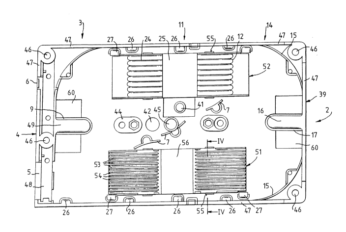
The housing for optical components comprises a lower housing
portion 2 and an unshown cover. The lower housing portion 2 is substantially
split up into a front entry area 3, a central area 11, and a rear area 14. The
15 front entry area 3 has entries and exits 5, 6 for the glass fibres integrated at the
front side 4, and a holding-down device 49 above a bottom opening 9 of the
lower housing portion 2. The central area 11 has holders 51, 52 for splices or
couplers, respectively, and curved deflection elements 7. The rear area 14 has
curved wall portions 15 for guiding the glass fibres, and a holding-down device
20 16, which is disposed above a bottom opening 17 of the lower housing portion
2. The areas 3 and 14 are selected so that the minimum bending radii for the
glass fibres are observed when introducing them into the holders 51, 52 for
splices or couplers, respectively. From the wall of the narrow side 39 provided
in the rear area 14, the holding-down device 16 above the bottom opening 17
25 iS formed. The bottom opening 9 is formed in the entry area 3 in the same wayas the bottom opening 17 of the area 14, and serves for guiding glass fibres in
and out, for instance, from another lower housing portion 2.
Between the holders 51, 52 for splices and couplers are provided
a pin 41, a bore 42, two elliptically-shaped portions 44 and a bore 45, to the
30 border of which a cylindrical wall having the height of the elliptically-shaped
portions 44 follows. The two elliptically-shaped portions 44 serve for the
2146502
-
attachment of the cover and for the attachment to an unshown subrack, or for
the adaptation of the housing to the installation environment, respectively. In
each elliptically-shaped portion 44 are a bore and a hexagonal depression.
Bores 46 located in the corners of the circumferential wall 47 also serve for the
attachment of the cover or for the combining of several lower housing portions
2, respectively. The entry 5 is integrated in the front side 4, or is configured as
a separate component and inserted in the front side 4. Behind the entry 5 is a
depression 48, into which a strain relief device can be inserted as a separate
component. The strain relief device is preferably composed of two plates
screwed together and having central recesses for the insertion of glass fibres.
The bottom openings 9, 17 in the lower housing portion 2 are each configured
with a portion 60 inclined towards the centre for optimum guidance of the glass
fibres.
From the wall 47 extend internally-formed holding-down devices
26 serving for safe guidance of the glass fibres. Between the wall 47 and the
holders 51, 52 for splices or couplers, respectively, are each formed two further
cable-guiding portions 27 providing, together with the holding-down devices 26,
for safe guidance of the glass fibres in the area of the holders 51, 52 for splices
or couplers, respectively.
The holders 51, 52 for splices or couplers, respectively, are
configured as separate, easily-exchangeable components with four latches 55
each that can be snap-fitted into recesses 59 at the bottom of the lower housingportion 2.
The holder 52 for couplers preferably comprises eight guide
grooves 24 forming the receiving portions 12 for preferably eight couplers. The
guide grooves 24 are interrupted by an approximately centrally-arranged free
area 25 extending transversely to their longitudinal direction, said free area
serving for the application of a glue material. The couplers are safely fixed bymeans of an adhesion film in the guide grooves 24. The free area 25 lies
slightly deeper than the deepest point of the guide grooves 24, so that by
_ 2146502
application of double-sided adhesion foils an additional coupler fixation can beachieved.
The upper side of the holder 51 for splices shown in Figures 2 to
4 comprises two comb-type sections between which a plane free area 56
extends over the full width of the holder 51. Each comb-type section is
composed of webs 53 disposed in parallel to the longitudinal axis of the holder
51 for splices and having an equidistant spacing from each other. Between
each two webs 53 is formed a groove 54 into which the glass fibre together with
the splice protection is inserted. The webs 53 are V-shaped at the ends, in
order to maintain the minimum bending radii when inserting the glass fibres.
The bottom areas of the grooves 54 are at the same height as the plane free
area 56. At the side faces are disposed two latches 55 each in the area of the
comb-type sections, said latches being snap-fitted into matching recesses 59
in the bottom of the lower housing portion 2. The plane free area 56 is
disposed centrally and extends approximately over one-fourth to one-fifth of thetotal length of the holder 51. The grooves 54 of the two comb-type sections are
aligned with each other. By constructing the holder 51 for splices with two
comb-type sections, a higher packing density for the placement of the splices
and a crossing of the fibres without falling below the admissible bending radii
are possible. Further, there is no necessity for additional detour lengths to, for
instance, repair splices, where fibre pieces are spliced in for extensions.
On the bottom side of the holder 51 for splices are semi-circular
depressions 57, the diameter of which approximately corresponds to the
diameter of the switch wires. Depressions 57 form, with semi-circular
depressions 58 in the bottom of the lower housing portion 2, closed channels
(Figure 4) through which the switch wires can individually be passed underneath
the holder 51 for splices. The bottom side of the holder 52 for couplers can be
configured in an analogous manner to the bottom side of the holder 51 for
splices.
3 0 By configuring the holders 51, 52 for splices or couplers,
respectively, as separate components to be snap-fitted to the lower housing
- 2146502
portion 2, a variable arrangement of the lower housing portion 2 with splices and
couplers is achieved. It is possible, for instance, to configure the housing as a
pure splice cassette, by snap-fitting a second holder 51 for splices into the lower
housing portion 2, instead of the holder 52 for couplers. When using planar
5 couplers for instance, a holder 52 for couplers is not required. When the splices
are not placed in a special splice holder, the holder 51 for splices is not
required, and a second holder 52 for couplers can be used instead. Thus the
packing density during assembly in external housing concepts is increased,
since then simpler constructions with higher numbers of input and output ports
10 are made possible. By the V-shaped configuration at the end of the webs 53,
introduction of the glass fibres is possible while observing the minimum bendingradii. This is particularly important when a glass fibre has to be introduced from
the one comb-type section into a groove 54 not aligned therewith of the other
comb-type section.