Note: Descriptions are shown in the official language in which they were submitted.
_WO 95/04489 PCT/KRg3/00126
~ 21~5~
CUSHION DEVICE
TECHNICAL FIELD
The present invention relates to a cushion device utilized for a
bed, sofa, chair, or seats for the use of the vehicle, etc., and more
particularly relates to a cushion device in which a person feels the
best comfort by manufacture process on the basis of the human body
engineering, and its life is semi-permanent.
BACKGROUND ART
There has been used sponges in a conventional device. Over
time the sponges have a drawback that the elasticity of the sponges
is to be reduced and finally lost because they are under weight
beyond their elastic limit. Recently, a cushion device, which has a
predetermined area as a network structure connected by steel springs,
has been developed. The conventional cushion device made of the
steel springs is shown in FIG. 1, which illustrates a part of cushion
device for a bed. In the conventional device, a plurality of steel
springs are connected with one another between an upper frame 1 and
an bottom frame 2 in a network type.
However, the conventional device has drawbacks which include a
complex manufacture process as well as m~king noises during cushion
movement and do not provide the best comfort, in view of the human
body engineering, due to the degree of a differently load against the
springs according to each of bending portions of the human body.
DISCLOSURE OF THE INVENTION
Therefore, to solve the above problems in the conventional
WO 95/04489 PCT/KR93/001
,
21~6~5 ~ 2
device, it is an object of the present invention to provide a cushion
device on which a person feels the best comfort by manufacture
process on the basis of the human body engineering.
It is the other object of the present invention to provide a
cushion device with almost no noises during cushion movement.
It is another object of the present invention to provide a cushion
device that is easy to m~nllf~cture and is semi-perm~nent in life.
To accomplish the above objects of the present invention, there
is provided a cushion device, the device comprising: an outer
supporting member which has a predetermined area and is formed to
include a shock absorbing space; and a cushion plate in which
includes bars that are located at a predetermined interval inside from
the outer supporting member and connected to the outer supporting
member by a plurality of elastic springs, and numbers of steel wires
that are elastically installed at regular intervals between the two bars.
BRIEF DESCRIPTION OF DRAWINGS
FIG.l is a perspective view showing an example of a
conventional cushion device.
FIG. 2 is a perspective view of a preferred embodiment o f a
cushion device according to the present invention.
FIG. 3 is an enlarged perspective view of A portion in the device
of FIG. 2.
FIG. 4 is a partially cut-away perspective view of a bed with a
cushion device according to the present invention.
FIG. 5 is a partially cut-away perspective view of a sofa with a
cushion device according to the present invention.
_WO 95/04489 PCT/KR93/00126
~ 2i4~5~
BEST MODE FOR CARRYING OUT THE INYE~TION
The preferred embodiment of the present invention will be
described below with reference to the accompanying drawings.
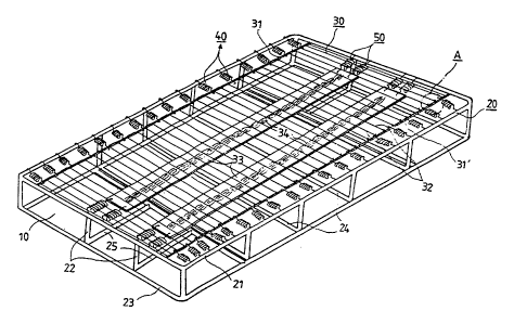
FIG. 2 is a perspective view of a preferred embodiment of a
cushion device for the bed according to the present invention. The
cushion device of the present invention comprises an outer supporting
member 20 which has a predetermined area and is formed to include a
shock absoring space 10. The outer supporting member 20 preferably
remains in a hollow pipe shape made of steels. The outer supporting
member 20 includes a first outer frame 21 with a predetermined area,
a plurality of supporting frames 22 which are extended downwards
from the first outer frame 21 so as to form the shock absorbing space
10, and a second outer frame 23 which are fixed to the supporting
frames 22 and are in a parallel arrangement with the first outer frame
21. A cushion plate 30 is elastically fastened to the first outer frame
21 of the outer supporting member 20 by a plurality of first elastic
springs 40.
The cushion plate 30 includes includes a pair of bars 31, 31 '
which are fastened to the outer supporting member 20 by a plurality
of the first elastic springs 40, and numbers of steel wires 32 that are
elastically installed at regular intervals between the two bars 31, 31'.
As shown in FIG. 2, in the case of a wide cushion plate, the cushion
plate 30 preferably further includes one plate spring 33 or more, which
are connected to the outer supporting member 20 by second elastic
springs 50. The plate spring 33 are placed transversely to a
plurality of the steel wires 32 and arranged to support them. On the
plate springs 33 strings 34 for tying a plurality of the steel wires 32
are made of nomnetal materials, and preferably cotton yarns. Here,
it is preferred to enh~nce tensile strength of the second elastic springs
50 rather than that of the first elastic springs 40.
WO 95/04489 PCT/l~;R93/00:1~
2 1~5~ 4
The cushion device of the present invention further incudes a
plurality of first reinforcing frames 24, being in a parallel arrangement
to the steel wires 32 at regular intervals, which are fixed between the
outer frames 21, 23 forming the shock absorbing space 10. Between
5 the first reinforcing frarnes 24 adjacent to the second outer frame 23
and the second outer frame 23, a second reinforcing *ames 25 are
preferably installed in a parallel arrangement to the plate springs 33 in
order to prevent the flexihility of the outer frames 21, 23 due to the
tensility of the springs.
FIG. 3 is an enlarged perspective view of A portion in the device
of FIG. 2. As shown in FIG. 3, after curving around the bar 31', the
ends of the steel wires 32 are bended and fastened to the inside of
bending portions. Accordingly, the fastened steel wires are securely
m;~int~inçll in a tied form under the load of the hllm~n body. In
15 addition, fixed members 35 are placed between each of the steel wires
32, so as to prevent the movement of each of the steel wires 32.
FIG. 4 shows a bed with an internal cushion device of FIG. 2.
Referring to FIG. 4, the cushion device of the present invention is
installed on bed legs 60 and includes in order a mat 70 and a sheet
20 cover 80 thereon.
FIG. 5 is a partially cut-away perspective view of a sofa with
an internal cushion device according to the present invention. As
shown in FIG. 5, the cushion device of the present invention is
installed on sofa legs 90 and includes a sheet cover 100 thereon.
INDUSTRIAL APPLICABILITY
As described above, a cushion device in accordance with the
present invention allows a person to feel the best comfort because it
30 gives a nearly equal elasticity to each of bending portions of the
human body when the person lies or sits thereon. Besides, the
~WO 95/04489 PCTlKRg3/00126
5 21~5~S~
device provides advanced advantages which is no noises, easy to
manufacture, and semi-permanent in life.