Note: Descriptions are shown in the official language in which they were submitted.
MAGNETIC MOTOR CONSTRUCTION
Backqround of the Invention
The present invention relates to means to produce useful
energy using permanent magnets as the driving source. The
present invention represents an important improvement over the
known constructions and one which is simpler to construct, can
be made to be self-starting, is easier to adjust, and is less
likely to get out of adjustment. The present construction is
also relatively easy to control, is relatively stable and
produces an amazing amount of output energy considering the
source of driving energy that is used. The present
construction, like the constructions disclosed in the earlier
applications, makes use of permanent magnets as the source of
driving energy but teaches a novel means of controlling the
magnetic interaction or coupling between the magnet members and
in a manner which is relatively rugged, produces a substantial
amount of output energy and torque, and in a device capable of
being used to generate substantial amounts of energy that is
useful for many different purposes.
The present invention resides in a fixed support structure
having one or more fixed permanent magnets such as an annular
permanent magnet mounted thereon with the pole faces of the
permanent magnet located adjacent opposite faces thereof. The
device has one or a plurality of relatively flat coils arranged
in a coplanar manner about the periphery on one of the opposite
faces of the fixed permanent magnet, and it has means for
journaling a shaft member that extends through the permanent
magnet with one or more other permanent magnet members attached
thereto at spaced locations, each of the one or more spaced
magnets having one of its magnetic poles positioned adjacent
to the fixed permanent magnet with the plane of the coils
positioned therebetween, the spaced permanent magnets and the
fixed permanent magnet having their polarities arranged to
produce a magnetic interaction such as magnetic coupling or
magnetic repulsion therebetween. The device also includes
-
7 4 i
-- 2
journal means for supporting the shaft member and the spaced
permanent magnet members for rotation relative to the fixed
magnet and to the coils thereon, and means for selectively and
sequentially energizing the coils located in a plane or space
between fixed and movable magnets to predeterminately control
the magnetic interaction forces between the respective spaced
permanent magnet members and the fixed magnet in such a manner
as to produce relative rotation therebetween. Various means
can be used to control the application of energy to the coils
including timer means under control of means mounted on the
shaft for rotation therewith and a source of energy. The
present construction can be made to be self-starting or to be
started with some initial help to establish rotation.
In accordance with one embodiment of the present invention
there is provided a device to control the magnetic interaction
between spaced permanent magnets comprising: a first permanent
magnet having opposite surfaces with north and south poles
respectively, a second permanent magnet spaced from and movable
relative to the first permanent magnet and having opposite
surfaces with north and south poles respectively, one of which
is positioned in close enough proximity to one of the surfaces
of the first permanent magnet to produce magnetic interaction
therebetween, a coil of conductive metal positioned in the
space between the first and second permanent magnets, a source
of electrical energy and switch means connected in series
therewith across the coil whereby when the switch means are
closed the electrical energy from the source is applied across
the coil whereby the magnetic interaction between the first and
second permanent magnets is changed, and means to control the
opening and closing of the switch means.
In accordance with a further embodiment of the present
invention there is provided a device for producing rotational
movement and torque comprising: a member journaled for
rotational movement about an axis of rotation, the rotatable
member having at least a portion adjacent the periphery thereof
~ t,
-
i 7 ~ 4
-- 3
formed of a permanently magnetized material, a stationary
member formed of permanently magnetized material mounted
adjacent to the peripheral port~on of the rotatable member
axially spaced therefrom whereby a magnetic interaction is
produced between the stationary and the rotatable members in
predetermined positions of the rotatable member, at least one
coil positioned extending into the space between the stationary
and rotatable members, means including a source of electric
potential and switch means connected in series across the coil,
and means to predeterminately control the opening and closing
of the switch means during rotation of the rotatable member to
vary the magnetic interaction in a way to produce rotation of
the rotatable member.
In accordance with yet another embodiment of the present
invention there is provided means to predeterminately vary the
magnetic interaction between first and second spaced permanent
magnet members comprising a first permanent magnet member
having north and south poles, a second permanent magnet member
having north and south poles spaced from the first permanen-t
magnet member by a gap therebetween, a coil positioned
extending into the gap between the first and second permanent
magnet members, means connecting the coil across a circuit that
includes a source of voltage and switch means connected in
series therewith so that when the voltage source is connected
across the coil it effects the magnetic interaction between the
first and second permanent magnet members, and means for
mounting the first permanent magnet member for movement
relative to the second permanent magnet member and relative to
the coil in the gap therebetween.
In yet another embodiment of the present invention there
is provided means for producing rotational movement comprising:
a support structure having a first permanent magnet mounted
thereon, the first permanent magnet having a north pole
adjacent one surface and south pole adjacent to the opposite
surface, means for mounting a second permanent magnet for
~ 9 ~ 4
- 3a -
rotational movement in a plane parallel to the first permanent
magnet, the second permanent magnet occupying an arcuate
portion of the mounting means less than the entire
circumference of the mounting means and having a north pole
adjacent to the opposite surface and positioned so that there
is a magnetic interaction between the spaced first and second
permanent magnets across a gap therebetween in at least one
position thereof, at least one air coil positioned in the gap
between the first and second permanent magnets, a source of
electric potential and switch means for controlling the
application of the electric potential from the source across
the air coil, the application of voltage across the air coil
effecting the magnetic interaction between the first and second
permanent magnet members in certain positions of the second
permanent magnet relative to the first permanent magnet and in
such a manner as to produce rotational movement of the second
permanent magnet.
A still further embodiment of the present invention
provides means for producing rotary motion using magnetic
energy from permanent magnets comprising: a fixed permanent
magnet having opposite surfaces with north and south poles
respectively adjacent thereto, a shaft having an axis and means
journaling the shaft for rotation in a position extending
normal to the opposite surfaces of the fixed permanent magnet,
a movable permanent magnet and means mounting the movable
permanent magnet on the shaft for rotation therewith, the
movable permanent magnet occupying an arcuate portion of the
mounting means less than the entire circumference of the
mounting means and having opposite surfaces with associated
north and south poles respectively, one pole of the movable
permanent magnet being positioned to move in close enough
proximity to one of the opposite surfaces of the fixed
permanent magnet to produce magnetic interaction therebetween,
at least one coil mounted in the space between the fixed
permanent magnet and the movable permanent magnet, energizing
: "
- ., . .~
-
i 7 ~ 4
- 3b -
of the coil effecting the magnetic interaction between the
fixed and the movable permanent magnets when positioned
therebetween, and means connecting the coil to a source of
energizing potential in selected positions of the movable
permanent magnet relative to the fixed permanent magnet.
Yet another embodiment of the present invention provides
for a magnetic device comprising: a fixed support structure
having a permanent magnet member mounted thereon, the member
having opposite side faces with a north magnetic pole adjacent
one side face and a south magnetic pole adjacent the opposite
side face, a plurality of coils mounted adjacent to and
arranged about one of the opposite side faces, an orifice
through the permanent magnet member at a location intermediate
the coils, a shaft extending through the orifice for rotation
about the axis thereof, a member attached to the shaft for
rotation therewith and spaced from the one opposite magnet side
faces, at least one magnet member attached to a segment of the
rotating member for rotation therewith, each of the rotating
magnetic members having a magnetic pole face positioned in
spaced relation to the one opposite pole side face of the fixed
permanent magnet member, the plurality of coils being in the
space formed by and between the fixed permanent magnet member
and the at least one rotatable magnet member, and means to
selectively and sequentially energize the coils as the shaft
rotates to predeterminately control the magnetic interaction
between the at least one magnetic member and that fixed
permanent magnet member.
In accordance with another embodiment of the present
invention there is provided a device for producing rotary
motion comprising: a support structure having a wall member,
a shaft and means journaling the shaft for rotation in the wall
member about its axis, a permanent magnet member mounted on the
wall member extending about at least a portion of the shaft,
the permanent magnet member having one pole adjacent to the
wall member and an opposite pole spaced therefrom, a member
7 7 4
- 3c -
mounted on the shaft having at least two magnetic members
oriented to produce magnetic interaction with the permanent
magnet member, a plurality of coils mounted in coplanar
relation extending into the space formed by and between the
permanent magnet member and the at least two magnetic members,
and means to sequentially apply a voltage across the respective
coils to vary the magnetic interaction between the permanent
magnet member mounted on the wall member and selected ones of
the at least two magnetic members.
Another embodiment of the present invention provides for
a device for producing rotary motion using magnetic energy from
permanent magnets comprising: a fixed permanent magnet having
opposite surfaces with north and south poles respectively
adjacent thereto, a shaft and means for journaling the shaft
for rotation extending normal to the opposite surfaces of the
fixed permanent magnet, at least two rotatable permanent
magnets and means mounting them for rotation with the shaft,
the rotatable permanent magnets having opposite surfaces with
associated north and south poles respectively, one pole of each
rotatable permanent magnet being positioned close enough to one
of the opposite surfaces of the fixed permanent magnet to
produce magnetic interaction therebetween, a plurality of
spaced coils arranged to be coplanar and positioned in the
space formed by and between the fixed permanent magnet and the
rotatable permanent magnets, and means to apply a voltage
across respective ones of the coils in a sequence so as to
predeterminately affect the interaction between the fixed
permanent magnet and the rotatable permanent magnets in a
manner to produce rotation of the at least two permanent
magnets.
A still further embodiment of the present invention
provides for a device for producing rotary motion using
magnetic energy from permanent magnets comprising: a fixed
annular permanent magnet having a flat surface on one side and
an opposite surface of helical shape extending therearound from
1~ '
,~
~ ~4~7~
- 3d -
a location of minimum thickness to a location of maximum
thickness approximately adjacent thereto, the annular permanent
magnet having one of its poles adjacent to the flat surface and
its opposite pole adjacent to the helical opposite surface, a
shaft and means for journaling the shaft for rotation extending
substantially normal to the flat surface of the fixed permanent
magnet, a permanent magnet and means mounting it on the shaft
for rotation therewith, the permanent magnet having opposite
pole faces and being positioned so that there is magnetic
interaction between the permanent magnet and the fixed annular
permanent magnet, at least one air coil positioned in the space
between the fixed and rotatable permanent magnets, and means
to apply a voltage across the air coil when the rotatable
permanent magnet is adjacent to the thickest portion of the
fixed permanent magnet to change the magnetic interaction
therebetween, the last name means including a source of voltage
and switch means in series with the source for controlling the
application of voltage across the air coil.
These and other features of the present invention will
become apparent after considering the following detailed
specification of preferred embodiments in conjunction with the
accompanying drawings.
Brief DescriPtion of the Drawings
Fig. 1 is a side elevational view of a magnetically
powered device constructed according to the present invention;
Fig. 2 is an exploded view of the device shown in Fig. l;
Fig. 3 is a fragmentary elevational view showing a
relationship between one of the movable magnet members and the
non-movable magnet member in one position of the device;
Fig. 4 is a view similar to Fig. 3 but showing the
relationship between the other of the movable magnet members
and the non-movable magnet member in the same position of the
device;
Fig. 5 is a fragmentary view similar to Fig. 3 but showing
a repulsion interaction between the relatively movable
-
- 3e - ~ 9 ~ ~ ~ 7 ~
permanent magnet members;
Fig. 6 is a view similar to Fig. 4 for the condition shown
in Fig. 5;
Fig. 7 is a side elevational view showing another
embodiment of the subject device which is capable of producing
even greater energy and torque;
Fig. 8 is a fragmentary elevational view similar to Fig.
3 for the device of Fig. 7;
Fig. 9 is a view similar to Fig. 4 for the construction
shown in Fig. 7;
Fig. 10 is a view similar to Fig. 3 for the device shown
in Fig. 7 but with the polarity of one of the fixed permanent
magnet members reversed relative thereto;
Fig. 11 is a fragmentary view similar to Fig. 4 for the
device as shown in Figs. 7 and 10;
Fig. 12 is a side elevational view of another embodiment
of the device;
PCT/US93/05628
W094/00903
~146771 ~4~
Fig. 13 is a schematic circuit diagram of the circuit
for the devices of Figs. 1, 7 and 12;
Fig. 14 is a perspective view of another embodiment of
the subject device;
Fig. 15 is a simplified embodiment of the device
showing the use of one rotating magnetic member and one coil
positioned in the plane between the rotating and stationary
magnetic members;
Fig. 16 is a simplified embodiment of the device
showing use of one movable magnetic member and three coils
arranged to be in a plane between the rotating and stationary
magnets.
Fig. 17 is a side elevational view of an air coil with
a voltage applied thereacross and showing in dotted outline
the field of the coil;
Fig. 18 is a view similar to Fig. 17 but showing the
air coil
positioned adjacent to one side of a permanent magnet showing
in dotted outline the magnetic field of the permanent magnet
with no electric potential applied across the air coil;
Fig. 19 is a side elevational view similar to Fig. 18
with an electric potential applied across the air coil, said
view showing in dotted outline the shapes of the electric
field of the air coil and the magnetic field of the permanent
magnet;
Fig. 20 is a side elevational view similar to Fig. 19
but showing a second permanent magnet spaced above first
permanent magnet and showing in dotted outline the magnetic
fields of the two permanent magnets when no electric
potential is connected across the air coil;
Fig. 21 is a view similar to Fig. 20 but with the
permanent magnets in an different relative position and with
a voltage applied across the air coil, said view showing the
shapes of the electro-magnetic field of the air coil and the
35~- modified shapes of the magnetic fields of the two permanent
magnets; and
Figs. 22-25 are similar to Fig. 21 and show the
~ 2 1 ~ 6 7 7 4 PCT/US93/05628
W~94/00903
-5-
electro-magnetic field of the air coil and the magnetic
fields of the magnets in four different relative positions of
the permanent magnets.
Detailed Description Of The Preferred Embodiments
Referring to the drawings more particularly by
reference numbers, number 10 refers to a device constructed
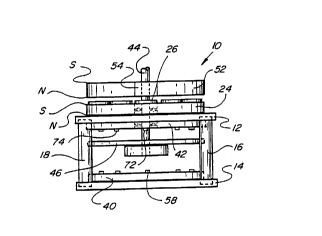
according to the present invention. The device 10 includes a
stationary base structure including an upper plate member 12,
a lower plate member 14, and spaced posts 16-22 connected
lo therebetween. Mounted on the upper plate 12 is a fixed
permanent magnet member 24 shown annular in shape which has
one of its poles (its North pole) adjacent the upper surface
thereof and its opposite pole (its South pole) spaced above
the plate 12.
Referring to Fig. 2, the permanent magnet member 24 is
shown having a plurality of coils 26-38 mounted in a coplanar
relationship on the upper surface thereof. Seven coils are
shown, and the coils 26-38 have electrical connections made
through the plate 12 to other circuit members which will be
described later in connection with Fig. 13. Another member
40 is mounted on the upper surface of the lower plate 14 and
a similar member 42 is mounted on the underside of the plate
12.
A shaft 44, (shown oriented vertically for convenience)
extends through aligned bores in the members 42, 12 and 24.
The lower end of the shaft 44 is connected to a disk member
46 which has a pair of spaced arcuate openings 48 and 50
shown located in diametrically opposite positions inwardly
from the edge of the disk 46. The purpose for the openings
48 and 50 will be explained hereinafter.
The shaft 44 is also connected to another annular
member 52 which is located on the shaft so as to be
positioned adjacent to the coils 26-38. The member 52 is
shown as disk shaped and it has a pair of spaced permanent
magnet members 54 and 56 mounted on or in it at spaced
locations shown diameterically opposite to one another (see
Fig. 2). The magnetic members 54 and 56 have their north and
W094/00903 ~1 4 6 7 7 4 PCT/US93/05628
south poles oriented as shown in Fig. 2, that is with north
poles shown on their lower sides and their south poles on the
upper sides. This is done so that there will be mutual
magnetic attraction and coupling between the magnets 54 and
56 and the fixed magnetic member 24. The polarity of the
magnets 54 and 56 and/or of the magnet 24 can also be
reversed if desired for some purposes to produce relative
magnetic repulsion therebetween.
Referring again to Fig. 2, the lower plate member 40 is
lo shown having a plurality of phototransistors 58-70 mounted on
the upper surface thereof at spaced locations therearound.
The number and locations of the phototransistors 58-70 are
such as to be in alignment substantially with the centers of
the respective coils 26-38 that are mounted on the member
24. A similar number of infrared emitters 72-84 are mounted
on the undersurface of the member 42 in alignment with the
respective phototransistors. There are seven infrared
emitters 72-84 shown, each of which is in alignment with a
respective one of the seven phototransistors 58-70 and a
respective one of the seven coils 26-38. This arrangement is
such that when the shaft 44 and the members attached thereto,
including the disk 46 and the member 52, rotate relative to
the other members including the member 24, the arcuate
openings 48 and 50 will pass between the respective pairs of
infrared emitters and in so doing will cause the
phototransistors periodically to be in optical communication
with the respective infrared emitters for predetermined time
intervals. The purpose of this communication is to establish
a sequence of energizing circuits to energize the respective
coils 26-38, one at a time, so that each coil in turn will
cause a momentary interruption of the magnetic interaction or
a portion thereof between respective ones of the permanent
magnets 54 and 56 and the magnet member 24.
When a coil is mounted on top of a permanent magnet
such as permanent magnet 24 and energized it acts to
concentrate the flux in a symmetrical magnetic field
resulting in a non symmetrical field when another parmanent
W094/00903 ~1~ 6 7 7 ~ PCT/US93/05628
--7-- .
magnet is placed above the coil that is located on the first
permanent magnet 24. This will result in uneven or
non-uniform forces being produced when the coil is energized
causing a torgue between the two permanent magnets, which
torque will be in the direction to try to move one of the
permanent magnets relative to the other.
Referring to Fig. 3 there is shown the position of one
of the magnet members 54 located immediately adjacent to one
of the coils such as the coil 26. In this position there
would be magnetic coupling between the magnets 54 and 24 so
long as there is no voltage across the coil 26. However, if
a voltage is placed across the coil 26 it will interrupt the
magnetic coupling between the magnets 54 and 24 where the
coil resides. This means that if there is any torque
developed, it will be developed to either side of the coil
26. Without energizing the coil 26 there will be full
attraction between the magnets 24 and 54 and no rotational
force will be produced.
Referring to Fig. 4 there is shown the relative
positions of the movable magnets 54 and 56 for one position
of the member 52. For example, the magnet 54 is shown
located immediately above the coil 26 while the magnet 56 is
shown straddling portions of the coils 32 and 34. If, in
this position of the members, the coil 32 is energized but
the coils 34 and 26 are not energized then the magnetic
coupling between the magnet 56 and the magnet 24 will be
oriented at an angle shown illustrated by the arrow in
Fig. 4, and this attractive coupling will tend to move the
member 52 to the right as shown in Fig. 4. Since there is no
energizing of the coil 26 there will be full coupling between
the magnet 54 and the member 24 but this will have no effect
since it will neither be in a direction to rotate the member
52 or to stop it. At this same time the coil 38 which is the
next coil over which the magnet 54 will move is likewise
deenergized and will therefore have no effect to produce
rotational moment of the member 52.
As the member 52 continues to rotate different ones of
W094/00903 2 1 ~ 6 7 7 ~ ~ ' PCT/US93/05628
-8-
the coils 26-38 will be energized in sequence to continue
producing magnetic coupling force between the members 52 and
24 in a direction to produce relative rotation therebetween.
It is to be noted, however that all of the rotational force
is produced by interaction between permanent magnet members
and none of the rotational force is produced by the coils or
by any other means. The coils are merely energized in
sequence to control where the magnetic interaction occurs,
and this is done in a manner to cause the member 52 to-~
rotate. It should also be understood that one or more,
including more than two, permanent magnets such as the
permanent magnets 54 and 56 can be mounted on the rotating
member 52, and the shape and size of the rotating member 52
can be adjusted accordingly to accommodate the number of
permanent magnets mounted therein. Also, the member 52 can
be constructed of a non magnetic material, the only
requirement being that sufficient structure be provided to
support the permanent magnets during rotation. This means
that the member 52 need not necessarily be constructed to be
round as shown in the drawing.
Figs. 5 and 6 are similar to Figs. 3 and 4 but show a
construction wherein the permanent magnets 54 and 56 are
overturned so that instead of having their north poles
adjacent to the member 24 they have their south poles
adjacent to the magnet 24 but on the opposite side of the
coils such as coils 26-38. The construction and operation of
the modified device illustrated by Figs. 5 and 6 is similar
to that described above except that instead of producing
magnetic attraction forces between the magnet members 54 and
56 and the magnet 24, magnetic repulsion forces are produced,
and these repulsion forces can likewise be used in a similar
manner to produce rotation of the member 52, whatever its
construction.
Fig. 7 shows a modified embodiment 100 of the subject
device which includes all of the elements shown in Figs. 1
and 2 but in addition has a second stationary permanent
magnet member 102 which is mounted above rather than below
W094/00903 ~1~ 6 7 7 4 PCT/US93/05628
_g_
the member 52 and has its coil members such as coil members
26A-38A mounted on its underside. The magnetic member 102
operates with the magnets 54 and 56 similarly to the member
24 and can operate in precisely the same manner, that is by
producing attraction force between the magnet members or by
producing repulsion forces therebetween, each being used to
produce relative rotational movement between the rotary
portions of the device and the stationary portions. It is
also contemplated to make the construction shown in Fig. 7 so
as to produce attraction forces between the magnets 54 and 56
on one side thereof and cooperating repulsion forces which
add to the rotation generating forces produced on the
opposite sides thereof.
Figs. 8 and 9 are similar to Figs. 3 and 4 but show the
relationship between the magnets 54 and 56 and the members 24
and 102 located on opposite thereof. Fig. 9 shows arrows
used to indicate the direction of the rotational forces
produced that are necessary for rotating the rotatable
portions of the device. These figures show one form of
interaction between the rotating magnets 54 and 56 and the
stationary magnets 24 and 102 located as shown in Fig. 7. In
this construction the device produces attractive rotating
force only.
Figs. 10 and 11 are similar to Figs. 8 and 9 except
that in these figures both attraction and repulsion forces
are shown being produced in association with the stationary
magnets on opposite sides of the rotating magnets. Note also
that the coils being energized on opposite sides of the
member 52 are energized in a different arrangement.
Fig. 12 is a side elevational view similar to Fig. 7
but illustrating the way in which a plurality of stationary
and rotatable magnetic members such as the members 24 and 102
can be mounted on the same shaft, in almost any number of
repetative groups to increase the amount of torque produced
by the device. In Fig. 12 the same power source and the same
circuit arrangement can be used to energize the
phototransistors and the infrared emitters. However,
677~
W094/00~3 - PCT/US93/05628
--10--
depending upon whether attraction or repulsion forces are
used to produce the rotation or some combination thereof will
depend upon the order in which the coils associated with the
stationary magnetic members are energized.
Fig. 13 is a circuit diagram for the device shown in
Figs. 1 and 2, showing the circuit connections for the coils
26-38 and for the circuit elements associated therewith. A
similar circuit can be used for the construction shown in
Figs. 7 and 12. The circuit also includes connections to the
various phototransistors and infrared emitters.
In Fig. 13, the circuit 120 is shown including a power
supply 122 which may be a battery power supply, a rectified
AC power supply or an AC or pulsed power supply. The
positive side 124 of the power supply 122 is shown connected
to one side of each of the coils 26-38, coil 26 and the
circuits associated therewith being shown in bold outline and
including connections to one side of a resistor 128 and to
one side of the photo transistors 58-70. The opposite side
of the coil 26 is connected to one terminal of Mosfet 126.
The opposite side of the resistor 128 is connected to one
side of the infrared emitter 72, as well as to the
corresponding sides of all of the other infrared emitters
74-84. The opposite sides of the infrared emitters 72-84 are
connected by lead 130 to the negative terminal side 132 of
the power supply 122. With the circuit as shown, the
infrared emitters 72-84 are all continuously energized and
produce light which can be seen by the respective
phototransistors 58-70 when one of the openings 48 or 50
passes therebetween. When this happens, the respective
phototransistor 58 will conduct and in so doing will apply
positive voltage on the associated Mosfet 126, turning the
Mosfet on, and causing the voltage of the source 122 to also
be applied across the coil 26. The circuit for this is from
the source 122 through the coil 26, through the Mosfet 126 to
35_ and through the lead 134 to the opposite side of the source
122. When the supply voltage is applied across the coil 26,
the coil 26 operates to limit or prevent magnetic
~094/00903 ~1~ 6 7 7 ~ PCT/US93/05628
communication between whichever one of the magnets 54 or 56
happens to be positioned adjacent to the coil 26 which is in
the space between that magnet 54 or 56 and the magnet 24.
This circuit is shown darkened in Fig. 13. By properly
timing and controlling the application of voltage to the
various coils 26-38 in the manner described, the magnetic
coupling between the magnets 54 and 56 and the magnet 24 can
be accurately controlled and in a manner to cause angular
magnetic attraction between the magnet 54 (or 56) and the
magnet 24, which angular attraction (or repulsion) is in a
direction to cause rotation of the rotating parts of the
structure shown in Figs. 1, 2, 7 and 12. It is to be
understood that each of the coils 26-38 will be controlled in
the same manner, that is, will have a voltage appearing
across it at the proper time to control the direction of the
magnetic coupling in a manner to produce rotation. The
rotating portions will continue to rotate and the speed of
rotation can be maintained at any desired speed. Various
means can be used to control the speed of rotation such as by
controlling the timing of the DC or other voltage applied to
the various coils, such as by using an alternating or pulsed
current source instead of a direct current source or by
loading the device to limit its rotational speed.
It is especially important to note that the energy
required to operate the subject device is minimal since very
little current is drawn when voltage is applied across the
various coils when they are energized.
A well known equation used for conventional motor art,
a well known formula is:
SPeed g Tor~ue = Power (in watts). Hence,
9.55
S x T = W.
9.55
This equation has limited application to the present
device because in the present device the torque is believed
to be constant while the speed is the variable. The same
equation can be rewritten:
T = 9.55 x W or S = 9.55 x W
S T
W094/00903 2 1 4 6 7 7 ~ PCT/US93/05628
-12-
These equations, if applicable mean that as the speed
increases, the watts divided by the torque must also increase
but by a factor of 9.55. Thus if torque is constant or
nearly constant, as speed increases, the power output must
increase and at a very rapid rate.
It should be understood that the present device can be
made to have any number of stationary and rotating magnets
arranged in stacked relationship to increase the power
output, (see Fig. 12) and it is also possible to use any
desired number of coils mounted on the various stationary
magnets. In the constructions shown in Figs. 1, 7, and 12
seven coils are shown mounted on each of the stationary
magnets but more or fewer coils could be used on each of
stationary magnet depending upon the power and other
requirements of the device. If the number of coils is
changed the number of light sources and photodetectors or
transistors will change accordingly. It is also important to
note that the timing of the turning on of the various
phototransistors is important. The timing should be such as
that illustrated in Fig. 4, for example, when one of the
coils such as coil 32 is energized to prevent coupling in one
direction between the magnet 56 and the magnet 24 the
adjacent coil 34 will not be energized. The reasons for this
have already been explained.
Referring to Fig. 14, there is shown another embodiment
140 of the subject device. The embodiment 140 includes a
stationary permanent magnet 142 which has a flat upper
surface 144 and a lower surface 146 that is circumferentially
helical so that the member 142 varies in thickness from a
location of maximum thickness at 148 to a location of minimum
thickness at 150. The thickness of the member 142 is shown
varying uniformly therearound. Near the location of the
thickest portion 148 of the permanent magnet 142 and adjacent
to the surface 144 is an air coil 152 shown formed by a
plurality of windings. A shaft member 154 is journalled by
bearing means 156 for rotation relative to the stationary
permanent magnet 142 and is connected to a rotating member
- ~146774
W O 94/00903 PC~r/US93/05628
-13-
158. The member is shown annular in shape and includes four
spaced permanent magnets 160, 162, 164 and 166 mounted on or
in it. The permanent magnets 160-166 are positioned to
rotate in closely spaced relation to the stationary permanent
magnet 142 but with the coil 152 positioned therebetween.
The coil 152 is connected into a circuit similar to that
shown in Fig. 13 and the circuit will not be described
further.
The principals of operation of the device 140 shown in
Fig. 14 are similar to that described above in connection
with Figs. 1 and other figures. It is important to note,
however, that the permanent magnets 160-166 rotate relative
to the permanent magnet 142 because of the increasing
coupling between them and the permanent magnet due to the
increasing peripheral thickness of the permanent magnet.
Thus the member 158 will rotate in a counterclockwise
direction as shown, and each time one of the magnets 160-166
moves into a position adjacent to the thickest portion 148 of
the fixed permanent magnet 142 the coil 152 will have voltage
applied across it, otherwise there would be a tendency for
the member 158 to stop or reduce the rotational force. In
order to overcome this the coil 152 is energized each time
one of the permanent magnets 160-166 is in the position
shown. The rotating disc 158 is connected through the shaft
154 to rotating disc 168 which has four openings 170, 172,
174 and 176 corresponding to the locations of the permanent
magnets 160-166 so that each time one of the permanent
magnets moves to a position adjacent to the thickest portion
148 of the stationary permanent magnet 142 the coil 152 will
3o be energized and this will reduce or eliminate the coupling
between the rotating and stationary magnets that would
otherwise slow the rotating portions down. The circuit
connected to the coil 152 includes the same basic elements
described above in connection with Fig. 13 including varying
a photocell 178, an infrared emitter 180 and a Mosfet 182
connected into a circuit such as that shown in Fig. 13. The
timing of the energizing of the coil 152 is important and
W 094/00903 '~ 1 ~ 6 7 7 ~ PC~r/US93/05628
-14- .
should be such that the coil will be energized as the
respective permanent magnets 160-166 move to a position in
alignment or substantial alignment with the thickened portion
148 of the stationary permanent magnet 142.
Fig. 15 shows a basic simplified form 190 of the
present device which includes a rotary member 52A having a
single permanent magnet portion 54A mounted thereon. The
device also has a stationary permanent magnet 24A with a
single air coil 26A positioned in the space between the
members 52A and 24A in the manner already described. The
construction 190 is not self-starting as are the preferred
embodiments such as embodiment 10 but the rotary portions
will rotate continuously once the device is started as by
manually rotating the rotary portions. The construction 190
will have other portions as described above but the output
from the construction will be less than the output produced
by the other constructions.
Fig. 16 shows another simplified version 200 of the
device wherein the member 52B is similar to the corresponding
rotatable member 52A shown in Fig. 15. However, the fixed
structure including the permanent magnet 24B has three
windings 26B, 28B and 30B located at spaced intervals
adjacent to the upper surface thereof. The construction
shown in Fig. 16 will produce more output than the
construction shown in Fig. 15 but less than that of the other
constructions such as that shown in Figs. l, 2, 7 and 12.
Obviously many other variations of the constructions shown in
the application are also possible including constructions
having more or fewer coils, more or fewer rotating magnetic
portions, more or fewer rotary members such as the member 52
and more or fewer stationary members such as the members 24
and 142.
Figs. 17-25 illustrate some of the underline principals
of the present invention.
Figs. 17 shows an air coil 210, positioned in space,
with an electric potential applied thereacross. With the
energizing-voltage applied the electro-magnetic field of the
W094/00903 ~1 4 6 7 7 4 PCT/US93/05628
-15-
air coil 210 extends substantially equally in the space above
and below the coil as shown in dotted outlined.
Fig. 18 shows the air coil 210 positioned adjacent to
one side (the north side) of permanent manget 212. In
Fig. 18 no voltage is applied across the air coil 210 and
therefore the air coil 210 does not produce an
electro-magnetic field as in Fig. 17. Under these
circumstances the air coil 210 has no effect on the magnetic
field of the permanent magnet 212 and the field of the
permanent magnet is substantially as shown by the dotted
outlines in Fig. 18.
Fig. 19 is similar to Fig. 18 except that in Fig. 19
the air coil 210 has an electric potential applied across it
and therefore has an established electro-magnetic field shown
again by dotted outline. The electro-magnetic field of the
air coil 210 modifies the magnetic field of the permanent
magnet 212 in the manner shown. If the coil 210 is placed in
contact with the surface of the permanent magnet and it is
energized so that its polarity is opposite to that of the
permanent magnet then the field produced is similar to that
shown in Fig. 19. Note that the field of the air coil 210 is
forced upwardly a greater distance than otherwise would be
the case if the air coil 210 were not positioned adjacent to
the permanent magnet 212. The field of the air coil 210
above the permanent magnet 212 is also more concentrated,
that is, there are more lines per square inch than is the
case in Fig. 17. This is because the lines that existed
below the coil before it was placed adjacent to the permanent
magnet 212 must now share the space above the coil with the
3o lines that occupy this space. In like manner, the field of
the air coil 210 modifies the shape of the magnetic field of
the permanent magnet 212 so that the field of the permanent
magnet occupying the space below the air coil 210 must share
the same area as the flux that occupied the perimeter of the
coil 210 before energizing. Therefore, the flux of the
permanent magnet 212 is more concentrated at the perimeters
of the air coil 210. Thus for the same amount of electrical
W O 94/00903 ~ ~ ~ 6 7 7 4 PC~r/US93/05628
-16-
input applied to the coil 210 shown in Fig. 17 the intensity
the electro-magnetic field of the coil 210 at the location
above the coil 210 is increased and magnetic field of the
permanent manget at other locations is increased.
Fig. 20 is similar to Fig. 19 except that a second
permanent magnet 214 is positioned at a location spaced above
the air coil 210. In Fig. 20 no voltage is applied across
the air coil 210 and therefore the air coil 210 does not have
an electro-magnetic field. Thus Fig. 20 shows only the
lo combined affect of the fields of the permanent magnets 212
and 214. Since the permanent magnets 212 and 214 are
oriented so that their respective north and south poles are
close together, there will be a strong attractive force
between them it the location of the air coil 210.
Fig. 21 is a view similar Fig. 20 but wth an electric
potential applied across the air coil 210 and with the upper
permanent magnet 214 displaced to the left relative to its
position in Fig. 20. Note that in Fig. 21 the shape of the
electro-magnetic field of the air coil 210 is concentrated
and shifted somewhat to the right and upward. This shift of
the electro-magnetic field concentrates the magnetic coupling
between the magnets 212 and 214 to the left thereby
increasing the tendency of the upper permanent magnet 214 to
move to the left. A much smaller magnetic coupling occurs
between the right end of the permanent magnets 212 and 214
and thus the force tending to move the permanent magnet 214
to the right is much less than the force tending to move it
to the left. ThiS is illustrated by the size of the arrows
shown in Fig. 21.
Figs. 22-25 show four different positions of the uppér
permanent magnet 214 relative to the lower permanent magnet
212. In Fig. 22 because of the position of the upper
permanent magnet 214 relative to the air coil 210 there is a
concentration of the magnetic coupling force tending to move
the upper permanent magnet 214 to the left. This force
increases in Figs. 23 and 24 until the upper permanent magnet
214 reaches the position shown in Fig. 25 where all of the
2146~74
W O 94/00903 PC~r/US93/05628
-17-
magnetic coupling is directed substantially vertically
between the permanent magnets 212 and 214 and in this
position there is little or no torque as a result of coupling
energy between the permanent magnets 212 and 214 tending to
move them relative to one another.
The principals illustrated in Figs. 17-25 are at the
heart of the present invention and explain where the energy
comes from to produce relative movement between the
relatively moveable permanent magnets.
The present device has application for very many
different purposes and applications including almost any
purpose where a motor or engine drive is required and where
the amount of energy available and/or required to produce the
driving force maybe very little to nil. Applicant has
produced devices of the type described herein capable of
rotating at very high speed in the order of magnitude of
20,000 RPMs and with substantial torque. Other lesser speeds
can also be produced, and the subject device can be made to
be self starting as is true of the constructions shown in
Figs. 1, 2, 7 and 12. Because of the low power required to
operate the device applicant has been able to operate same
using a commerically available battery such as a nine volt
battery.
Thus there has been shown and described a novel
magnetic motor or motor-like construction which fulfills all
of the objects and advantages sought therefor. It will be
apparent to those skilled in the art, however, that many
changes, variations, modifications and other uses in
applications for the subject device are possible. All such
3~ changes, variations, modifications and other uses in
applications which do not depart from the spirit and scope of
the invention are deemed to be covered by the invention which
is limited only by the claims which follow.