Note: Descriptions are shown in the official language in which they were submitted.
WO94/08513 2 1 ~ 7 0 0 1 PCT/US93/08728
PERCUTANEOUS VASCULAR SEALING APPARATUS AND METHOD
TECHNICAL FIELD
This invention relates to a novel apparatus and method
for percutaneously sealing a puncture in a blood vessel
wall following an invasive medical procedure. More
specifically, this invention relates to a vascular
sealing apparatus and method of employing electrosurgical
sealing to rapidly seal a puncture site in a blood vessel
wall following removal of a sheath assembly from the
blood vessel wall.
BACKGROUND ART
Percutaneous vascular procedures form an integral portion
of radiological and cardiological medical practices.
It is estimated that approximately one million invasive
procedures are performed eachyear, includingperipheral
and carotid angiograms, catheterizations, angioplasties,
and atherectomies. In such procedures, a puncture
opening distending sheath assembly is introduced into
a blood vessel, for example, the femoral artery in a
patient's leg. A medical device, such as a catheter,
is introduced through the sheath assembly and then
advanced through the blood vessel to the coronary, or
= other operative, region.
The majority of these invasive procedures are performed
using the Seldinger technique to gain percutaneous
vascular access to the blood vessel. According to this
W O 94/08513 PC~r/US93/08728 2147VO~ -2-
technique, the blood vessel, which in the case of the
femoral artery is typically located one half inch or more
beneath the skin, is punctured through the overlying
tissue by a hollow-core needle. A guide wire then is
threaded through the hollow core of the needle and into
the artery. The needle is subsequently withdrawn from
the artery, while the guide wire is maintained in place.
Next, a blood vessel wall dilator and a thin-walled,
tubular, puncture-distending sheath are introduced into
the artery with the blood vessel dilator inside the
sheath. The dilator and the sheath are moved along the
guide wire and through the puncture site to an
intravascular position. The dilator extends outwardly
of the end of the sheath and gradually distends the
puncture opening as it is advanced into the blood vessel
wall until the opening will receive the sheath. The
guide wire and the dilator are then withdrawn from the
artery while the distending sheath assembly is left in
place. Prior to the introduction of medical devices into
the artery, anti-coagulants are administered to prevent
blood clotting. Finally, a catheter, or other medical
device, may be inserted through the sheath assembly to
perform the necessary invasive procedure.
Following the medical procedure, the medical device is
removed from the sheath assembly and the sheath assembly
is removed from the puncture site in the artery. The
time which elapses prior to sheath removal varies
considerably depending on the procedurebeingperformed.
Other factors which govern the amount of lapsed time
prior to sheath removal include the size of the sheath
employed, the amount ofanti-coagulant administered, and
the patient's clinical circumstance. The combinations
of all of these factors often results in a relatively
long waiting period between the completion of the
procedure and the removal of the sheath assembly, which
adds to patient discomfort and anxiety.
WO94/08513 21 ~ 7 D ~ I PCT/US93/08728
Once the sheath assembly is removed from the artery, it
has been customary to obtain hemostasis at the puncture
site by applying indirect, external pressure to the
femoral artery and vein. This is usually accomplished
manually by a nurse or physician, or with the aid of a
mech~nical clamp, employed by the nurse or physician.
Often, compression must be applied for ten to thirty
minutes before sufficient clotting occurs. Once
hemostasis is achieved, a pressure dressing is typically
applied to the patient's leg for several hours. In
addition, six to twelve hours of bed rest is typically
required to reduce the risk and incidence of hematoma
formation.
Although manual compression has proven successful in
obtaining hemostasis over the years, there are numerous
problems and disadvantages associated with this method.
The procedure is extremely time-consuming from both a
patient and a physician standpoint and further is an
inefficient use of the medical professional staf~.
Moreover, manual and mech~n;cal compression are extremely
l~ncomfortable to the patient and frequently is associated
with vaso-vagal episodes. In addition, bruise or
hematoma formation at the entry site often occurs as a
result of internal bleeding of the punctured artery
before clotting blocks the puncture. The possibility
of psuedoaneurysm formation also exists with the manual
compression technique of achieving hemostasis.
In response to some of the problems associated with
manual compression, a percutaneous apparatus and method
for forming a vascular seal has been developed and
- commercially exploited under the trade name VASOSEAL by
Datascope Corporation of Montvale, New Jersey. According
- to this method, a measuring device is used to calculate
the distance between the skin surface and the operative
vessel wall at the beginning of the catheterization
W094/08513 PCT/US93/08728
~2 1 ~ 4_ ~
procedure. Then, when the invasive procedure is
completed and the medical device and distending sheath
assembly have been withdrawn, an applicator is inserted
through the patient's skin and overlying tissue down the
passageway formerly receiving the sheath assembly to the
previously measured depth. The applicator is actuated
to deliver a volume of collagen to the puncture site.
The collagen utilized by the Datascope apparatus and
method is made of resorbable natural fibers and attracts
and activates platelets to form a coagulum at the vessel
surface, sealing the surface of the artery. Such a
collagen seal is typically formed in less than five
minutes, involving significantly less time and labor than
that required by the manual compression technique. The
collagen itself applies a discrete pressure against the
blood vessel wall, much like finger pressure delivered
to a skin wound, but some direct, external pressure still
must be applied to the entry site once the collagen has
been injected.
Although the Datascope method significantly reduces the
amount of manual compression required, the necessary
manual compression remains an inefficient use of a
physician's time. Moreover, the Datascope method
involves some risk associated with deploying collagen
intravascularly, or only at an approximate location along
the vessel wall, rather than at a specific, identifiable
position on the vessel wall surface. For example,
manipulation of the blood vessel during the
catheterization procedure may cause the blood vessel to
shift, reducing the accuracy of the measurement taken
before the catheterization procedure. Intravascular
deposition of collagen can produce an embolism and
possible ischemia within the patient's leg, which may
require further medical intervention. Deposits of
collagen remote of the puncture site may be ineffective
in establishing hemostasis.
W094/08513 '~ 7~ PCT/US93/08728
Another method for closing and sealing an artery
following removal of a catheter is disclosed in U.S.
Patent No. 4,929,246 to Sinofsky. This method involves
applying laser energy to a puncture site to thermally
weld the artery. In a preferred embodiment, a sheath
assembly is withdrawn to a spaced distance from the
artery and puncture site and a tube having a balloon at
its distal end is advanced through the sheath assembly.
The balloon is then inflated to apply pressure to the
exterior wall of the artery, temporarily blocking blood
flow from the puncture. The tube also carries an optical
fiber which extends into the balloon and directs a beam
of laser energy against the interior of the balloon.
The laser energy indirectly thermally welds the artery
wall. Creating a vascular seal with a laser as disclosed
in the Sinofsky patent, however, is a costly, somewhat
indirect and a complex solution to hemostasis.
It also is widely known in the medical field to heat weld
exposed blood vessels during an operative procedure or
to electrosurgically coagulate escaping blood to effect
vascular sealing. For example, laser energy has been
routinely directly employed to provide the necessary
thermal energy to weld brachial arteries during a Sones
procedure. In addition, both electro-cautery and
electro-coagulation have been used to seal exposed small
blood vessels under direct observation during operative
procedures. It is believed that such electrosurgical
procedures have not previously been employed to effect
rapid percutaneous vascular sealing of unseen blood
vessels following an invasive medical procedure.
The difficulties suggested in the preceding are not
intended to be exhaustive but rather are among many which
tend to reduce the effectiveness of and physician
satisfaction with prior percutaneous vascular sealing
devices. Other noteworthy problems may also exist;
WO94/08513 PCT/US93/08728
2 14~ 0~ -6-
however, those presented above should be sufficient to
demonstrate that such vascular sealing apparatus and
methods appearing in the past will admit to worthwhile
improvement.
Accordingly, it is therefore a general object of the
invention to provide percutaneous vascular sealing
apparatus and method which will obviate or minimize
difficulties of the type previously described.
It is a specific object of the invention to provide a
percutaneous vascularsealing apparatus and methodwhich
rapidly creates a vascular seal at a puncture site in
a blood vessel wall following an invasive medical
procedure.
It is another object of the invention to provide a
percutaneous vascular sealingapparatus and methodwhich
enables accurate identification of an external surface
of an operative blood vessel, thereby preventing
accidental actuation of the sealing apparatus at an
intravascular location or an ineffective remote location.
It is still another object of the invention to provide
a percutaneous vascular sealing apparatus and method
which reduces the amount of medical staff care necessary
to achieve hemostasis following an invasive medical
procedure, allows a patient to be ambulatory soon after
the procedure, and, thereby, reduces the length of the
hospital stay.
It is a further object of the invention to provide a
percutaneousvascularsealing apparatus and methodwhich
eliminates the need for mechanical clamps to effect
hemostasis and reduces the time required for pressure
dressings upon completion of an invasive medical
procedure.
~ 094/08Sl3 2 1 ~ 7 ~ O ~ PCT/US93/08728
It is yet a further object of the invention to provide
a percutaneous vascular sealing apparatus and method
which reduces the risk of rebleeding, hematoma formation,
and psuedoaneurysms formation following an invasive
medical procedure.
It is still a further object of the invention to provide
a percutaneous vascular sealing apparatus and method
which reduces patient pain and discomfort associated with
invasive medical procedures.
It is yet another object of the invention to provide a
percutaneous vascularsealing apparatus and method which
is relatively inexpensive to manufacture and use, is
disposable, and, thus, is practical for everyday use.
DISCLOSURE OF Ihv~llON
Apreferred embodiment ofthe inventionwhich is intended
to accomplish at least some of the foregoing objects
includes a vascular sealing assembly having an elongated
member, most preferably an elongated tubular mem~er,
formed for temporary positioning through overlying tissue
and up to and preferably into a blood vessel through a
puncture opening at a puncture site in the blood vessel.
The elongated member is formed for cooperative engagement
with a guide device which guides the elongated member
to the puncture site in the blood vessel. A sealing
element is positioned on the elongated member at a
location registered or indexed relative to a transversely
extending, blood vessel-locating, shoulder on the
elongated member for substantially direct engagement of
the sealing element with an exterior surface of the blood
vessel wall. An energy source is connected to the
sealing element for generating energy sufficient to
enable hemostasis of the puncture site, for example, by
electro-cauterization or electro-coagulation.
WO94/08513 PCT/US93/08728
2147~ 8-
Invasive medical procedures generally entail inserting
catheters and/or other medical instruments or devices
through a puncture-distending sheath which extends
through overlying tissue and into an operative blood
vessel through a puncture site. The puncture opening
in the blood vessel wall must be sealed upon completion
of the procedure. The method of the present invention
provides for positioning of a vascular sealing assembly
in substantially direct engagement with a blood vessel
wall following such an invasive medical procedure to
enable sealing of the puncture opening in the wall. The
method includes the stepsof (i) aligning elongated guide
device with the puncture site through the tissue
overlying the blood vessel, and (ii) moving at least one
of the sealing assembly and the guide device relative
to each other until a transversely extending shoulder,
preferably the end of the sealing assembly, encounters
increased resistance to movement toward the blood vessel
as a result of substantially direct engagement with a
wall of the blood vessel at the puncture site. A
vascular seal may thenbeobtainedby applyingsufficient
heat or coagulating energy to the blood vessel while the
sealing assembly is maintained in substantially direct
contact with the exterior surface of the blood vessel
to effect hemostasis of the puncture site.
Other objects and advantages of the present invention
will become apparent from the following detailed
description of a preferred embodiment thereof taken in
conjunction with the accompanying drawings.
BRIEF DESCRIPTION OF THE DRAWING
FIGURE l is an enlarged, schematic, side elevation view
of a percutaneous puncture site in a blood vessel having
a puncture-distending sheath assembly and a guide wire
positioned to extend from the exterior of the overlying
tissue to inside the blood vessel.
W O 94/08513 21 ~ 7~ ~ P~r/US93/08728
_9 _ 7 ~
FIGURE 2 is a reduced, schematic, side elevation view
illustrating insertion of a sealing assembly through the
sheath assembly and into a blood vessel in accordance
with a preferred embodiment of the invention.
FIGURE 3 is an enlarged, schematic, side elevation view
of the sealing assembly of FIGURE 2 positioned in the
blood vessel through the sheath assembly.
FIGURE 3A and FIGURE 3B are side elevation views
corresponding to FIGURE 3 and illustrating alternative
sheath and sealing assembly configurations.
FIGURE 4 is an enlarged, schematic side elevation view
of the sheath assembly and sealing assembly of FIGURE
3, as withdrawn from the blood vessel for sealing of the
puncture site.
FIGURE 5 is a schematic, side elevation view illustrating
withdrawal of the guide wire from the blood vessel after
partial heat cauterization.
FIGURE 6 is a schematic, bottom plan view of a sealing
assembly constructed in accordance with a preferred
embodiment of the invention.
FIGURE 7 is a schematic, side elevation view illustrating
an alternative embodiment of the apparatus and method
of the present invention.
FIGURE 8 is an enlarged, end view of the electrosurgical
tip on the distal end of the sealing assembly of FIGURE
7.
.
FIGURE 9 is a schematic, side elevation view
corresponding to FIGURE 7 illustrating still a further
embodiment of the method of the present invention.
W O 94/08513 .: PC~r/US93/087~
. - ` ~
FIGURE 10 is a schematic, side elevation view of an
alternative embodiment of the subject sealing assembly
positioned through a sheath assembly and into a blood
vessel.
FIGURE 11 is a schematic, side elevation view of the
subject sealing assembly being inserted through overlying
tissue to a blood vessel wall in accordance with still
another alternative embodiment of the method of the
present invention.
BEST MODE OF CARRYING OUT THE INVENTION
Referring now to the drawings, wherein like numerals
indicate like parts, FIGURES 1-5 illustrate a sequence
of steps for percutaneously sealing a puncture opening
inablood vessel following aninvasivemedical procedure
in accordance with a preferred embodiment of the method
of the present invention.
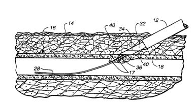
In FIGURE 1 there will be seen a puncture-distending
sheath assembly, generally indicated 10, which includes
an elongated, tubular, sheath member 12 positioned
through overlying tissue 14. Sheath 12 extends into a
blood vessel 16 through a puncture opening or bore 17
in blood vessel wall 18. The sheath serves as a conduit
to the blood vessel during the invasive procedure,
maintaining puncture opening 17 through blood vessel wall
18 distended so that medical devices can be inserted
through assembly 10 into blood vessel 16.
The diameter of sheath 12 may range from approximately
5 French to 14 French, depending on the particular
procedure to be performed, and inserting sheath 12 into
blood vessel 16 creates a similarly sized puncture
opening 17 through vessel wall 18. Placement of sheath
12 through tissue 14 and vessel wall 18, as shown in
FIGURE 1, is most typically accomplished using the
WO94/08513 -11- ~ ~0~
Seldinger technique, described briefly above. The
invasive medical procedures may include peripheral and
carotid angiograms, catheterizations, angioplasties, and
atherectomies.
Sheath member 12 has an indwelling or annular distal end
20, an exposed end 22, and a bore or lumen 24 which
provides a conduit or pathway for medical devices and
instruments into blood vessel 16. During catheterization
procedures, for example, a catheter may be inserted
through lumen 24 of sheath 12 to be positioned in blood
vessel 16, normally the femoral artery, and then advanced
through the blood vessel to the treatment site. Sheath
assembly 10 also typically includes a port assembly 26,
for example, of the type set forth in U.S. Patent No.
4,424,833, which is mounted to exposed end 22 of sheath
12 for receipt of, and cooperative and usually sealed
engagement with, catheters and othermedical instruments
and devices employed during the medical procedure.
once the medical procedure is completed, it is necessary
to seal puncture 17 through which sheath assembly lO
extends. The procedure or method of the present
invention includes as a first step, aligning elongated
guide means with the puncture site, which guide means
extends from the puncture site through overlying tissue
14.
The aligning step can be accomplished during insertion
of sheath assembly 10 into puncture 17, if the sheath
assembly is employed as the guide means. Most
preferably, however, a guide means, such as guide w re
28 used in the Seldinger technique, can be reinserted
into sheath assembly 10 after removal of the medical
device used in the invasive procedure. In either case,
an elongated guide wire 28 or elongated sheath member
12, which is now also a guide member, is positively
WO94/08513 PCT/US93/08728
2 1~ QQ1 -12-
axially aligned with the central longitudinal axis of
puncture opening 17. The guide means preferably, but
not necessarily, extends through puncture 17 to provide
positive alignment.
As best may be seen in FIGURE 2, in the preferred
embodiment of the method of the present invention, a
sealing assembly, generally designated 30, is mounted
over guide wire 28 and moved in the direction of arrow
A down the guide wire and through sealing assembly 26
into sheath member 12. In the preferred embodiment,
sealing assembly 30 is an electrosurgical device suitable
to effect cauterization or coagulation and including an
elongated tubular member 32 which carries one of a
heating or coagulating assembly 34 on its annular end.
The preferred sealing assembly will be described in more
detail in connection with FIGURE 6.
The next step in the method of the present invention is
the step of moving at least one of the guide means and
a sealing assembly axially relative to the other and to
puncture 17 until a transversely extending shoulder on
at least one of the guide means and sealing assembly
encounters increased resistance to movement as a result
of substantially direct engagement of the shoulder with
wall 18 of the blood vessel. Thus, as is preferred and
shown in FIGURES 1-5, sealing assembly 30 and sheath
12 are withdrawn or moved together axially on guide wire
28 until a transverse shoulder thereon is guided into
substantially direct engagement with wall 18 around
puncture 17.
Since there are numerous brands and lengths of sheath
assemblies 10 commercially distributed, FIGURES 1-5
illustrate a sealing assembly 30 in which tubular
elongated member 32 has been provided with a length
greater than the length of tubular sheath member 12.
W094/08513 ~ 2 1 ~ 7 o ~ ~ PCT/US93/08728
Thus, annular distal end 36 of member 32 will extend
beyond annular distal end 20 of sheath member 12.
Conventional sheath assemblies 10 are provided with
relatively thin-walled, tubular sheath members 12. Thus,
inthepreferred method ofthepresent invention positive
location of the exterior surface 40 of blood vessel 18
surrounding puncture 17 is accomplished using annular
end wall 36 of sealing assembly 30 as the transversely
extendingshoulder. As is describedbelow, a specialized
thick-walled sheath member 12 would also enable use of
the sheath assembly end wall 20 as a shoulder to locate
surface 40, and if the sealing member 32 and sheath have
the same length, as shown in FIGURES 3A and 3B, a
combination of end walls 36 and 20 can be employed.
The preferred method of moving sealing means and the
sheath into engagement with surface 40 is to move sheath
12 and sealing means 30 together relative to guide wire
28, namely, by slowly withdrawing sheath 12 and sealing
member 32 from a position inside puncture 17 (FIGURE 3)
along wire 28 to a position outside puncture 17 (FIGURE
4).
When the annular end 36 of tubular sealing means 32 is
withdrawn from puncture 17, at least one of two phenomena
will occur. First, for most blood vessels, wall 18 will
be sufficiently resilient that withdrawal of sheath 12
and sealing member 32 will cause resilient contraction
of wall 18 at puncture 17 down around guide wire 28.
Second, even when blood vessel walls 18 are not very
resilient and contract only slightly, if at all, removal
of sheath 12 and sealing member 32 automatically will
result in guide wire28, which has a transverse dimension
substantially less than the distended puncture opening,
being laterally displaced from the center of puncture
opening 17 to proximate one side of the puncture. Thus,
W O 94/08513 . . PC~r/US93/08728
2147~ 14- ~
the annular shoulder or end 36 now will be guided along
a laterally displaced guide wire 28. In either case,
movement of the sealing assembly and sheath, back toward
blood vessel 16 will result in shoulder or annular end
36 substantially directly engaging exterior surface 40
of wall 18 at the puncture site. Such engagement of the
annular shoulder of the sealing means with wall 18 will
result in the occurrence of an increased resistance to
movement toward the blood vessel, as compared to the
resistance to movement present during withdrawal of the
sheath and sealing member.
In the preferred procedure of FIGURES 1-5, therefore,
sheath assembly 12 and sealing assembly 30 are slowly
withdrawn by a short distance from within puncture 17
and then advanced slightly. This is repeated with
slightly larger withdrawal distances than advancement
distances until withdrawal from the blood vessel occurs
and an increased resistance can be felt or sensed on the
next advance toward the blood vessel.
As used herein, the expressions "substantially direct
engagement" and "substantially direct contact" shall
include direct abutting contact by end 36 with surface
40 of wall 18 and engagement in which the shoulder is
separated from surface 40 of wall 18 only by a very thin
layer of tissue 14, for example, a layer substantially
less than the thickness of blood vessel wall 18.
Once annular end wall or shoulder 36 of sealing means
30 is brought into substantially direct engagement with
wall 18 around puncture 17, the method of the present
invention includes the step of sealing puncture 17, most
preferably by electro-cauterizing or electro-coagulating
blood escaping from contracted puncture 17. It will be
understood, however, that other puncture sealing
techniques can be employed once sealing means end 36 is
WO94/08513 21 ~ 70Q~ PcT/us93/o8728
-15-
positively guided into substantially direct contact with
the puncture site.
As may be seen from FIGURES 4 and 5, electrosurgical
sealing preferably is a two step procedure in which most
of the area of puncture 17 is heat cauterized or
coagulated, while guide wire 28 extends through puncture
17 (FIGURE 4). The area of guide wire 28 is next heat
cauterized or electro-coagulated after removal of guide
wire 28, as shown in FIGURE 5. It should be noted that
the substantially direct engagement of the puncture site
byshoulder or end36during electrosurgical sealing also
tamponades the puncture site to aid the hemostasis
process. After removal of wire 28 and sealing of the
guide wire opening, sheath assembly 10 and sealing
assembly 30 can be withdrawn together from tissue 14.
In order to provide the maximum shoulder dimension for
location of surface 40 around puncture 17, sheath
assembly 10 and sealing assembly 30 ideally have lengths
and end configurations which are matched or can be
manipulated until the ends are substantially coplanar.
As may be seen in FIGURE 3A, therefore, end 20' of sheath
member 12' and end 36' of sealing assembly 30' are
coplanar and oriented at an angle to guide wire 28' to
engage surface 40' proximate puncture 17' at an angle
close to parallel to blood vessel wall 18'. When the
combined annular shoulder comprised of annular walls 20'
and 36' are withdrawn from opening 17', the next advance
of the sheath and sealing means toward the blood vessel
will be met with a substantial increase in resistance.
In FIGURE 3B, ends 20" and 36" again are substantially
coplanar, but they are oriented at about ninety degrees
to guide wire 28". Thus, they present a large combined
shoulder, but the shoulder is not substantially parallel
to blood vessel wall 18".
-
WO94/08513 sr ~ PCT/US93/08728
2~700~ -16-
Guided movement of a shoulder into substantially direct
contact with blood vessel 16 can be accomplished using
other manipulation techniques. Thus, as may be seen from
FIGURE 7, puncture-distending sheath assembly 10 has been
used to reintroduce guide wire 28a into blood vessel 16a
through puncture 17a. The sheath assembly has been
removed from blood vessel 16a and tissue 14a, leaving
guide wire 28a in place. A sealing assembly 30a, having
elongated tubular sealing member 32a, is then mounted
over guide wire 28a and advanced slowly in the direction
of arrow B toward puncture 17a. In order to insure
location ofthe exterior surface 40a ofblood vessel wall
18a, sealing assembly member 32a can have a diameter
which is greater than the diameter of the removed sheath
assembly. For example, if the sheath assembly had a
diameter of 8 French, member 32a may have a diameter of
10 or 12 French.
When sealing member end shoulder 36a reaches the
contracted wall 18a at puncture site 17a, or is guided
by laterally shifted wire 28a into contact with surface
40aofwall 18a, increased resistancetoadvancement will
be sensed by the doctor, indicating that end 36a is in
substantially direct engagement with the puncture site.
Electrosurgical or other forms of sealing then can
proceed as above described.
In the procedure illustrated in FIGURE 9, the instrument
or device used in the medical procedure is first removed
from sheath assembly lOb. Since the puncture-distending
sheath member usually is a relatively thin-walled member,
it is preferable that the original sheath be replaced
by a sheath member 12b having a relatively thick wall
so that the annular shoulder 20b has sufficient
transverse dimension to be used to locate surface 40b
surrounding puncture. Elongated member 32b of sealing
means 30b is then introduced and guided down lumen 24b
W094/085l3 2~ ~ 7 0 ~ 1 PCT/US93/08728
-17-
until end 36b is inside blood vessel 16b to align the
sealing assembly with the longitudinal axis of puncture
17b.
In the procedure of FIGURE 9, sheath assembly 10b is now
slowly withdrawn, preferably by short reciprocating
cycles in which the sheath is first withdrawn and then
advanced on sealing member 32b, which now acts to guide
sheath 12b. The withdrawal portion of each cycle should
be slightly greater in distance than the advancement
portion so that annular end shoulder 20b of the sheath
will eventually be withdrawn from wall 18b. Once end
20b is withdrawn, the next advancement step will cause
it to be advanced against the contracted wall or side
of puncture 17b toward which member 32b is automatically
laterally displaced when sheath 12b clears puncture 17b.
The result is that the doctor can feel when shoulder 20b
is withdrawn from the puncture and then advanced back
against exterior surface 40b of wall 18b. When increased
resistance to advancement of sheath 12b is felt,
transverse shoulder 20b will be in substantially direct
contact with the puncture site, and sealing member 32b
has positively maintained the alignment of the sheath
during location of the wall surrounding the puncture
site. Now, sealing assembly 30b can be moved slowly out
of puncture 17b until end 36b of the sealing tip is
proximate annular sheath shoulder 2Ob. This can be
facilitated, for example, by placing indicia, such as
lines 33 on outer end of sealing member 32b. The first
of lines 33 may indicate, for example, that end 36b is
one or two millimeters from end 20b and the next line
33 can indicate that the two ends are coplanar. It will
be seen from FIGURE 9 that sheath end 20b is optionally
formed to be inclined in a manner similar to end 36b of
the sealing assembly so that both will mate with or be
more closely aligned with surface 40b.
WO94/08513 PCT/US93/08728
2~470~1 -18-
Electrosurgical or other sealing can begin, for example,
at the first of the two lines 33 and proceed as the
sealing member 32b is withdrawn inside sheath 12b to the
second of lines 33. Additional lines 33 can be provided
as desired. The sealing tip 36b of sealing assembly 30b
can be a solid or unperforated tip since no guide wire
is required for this procedure. Unperforated end 36b
also aids in its tamponade-effect during hemostasis.
The method described in connection with FIGURE 9 may be
somewhat less desirable than the method of FIGURES 1-5,
3A, 3B and 7 in that the shoulder 20b provided by sheath
12b will not be as large as the annular shoulders 36,
20' and 36', 20" and 36" and 36a. In the FIGURE 9
procedurethe sealingmeansmaintains positive alignment
as cauterization starts and is withdrawn as it ends.
It also may be possible to use the original thin-walled
sheath and still sense the blood vessel wall upon
withdrawal along sealing means 30b, but substitution of
a thick-walled sheath 12b will facilitate tactile sensing
of the increased resistance.
Still a further embodiment of the procedure of the
present invention canbe describedby reference toFIGURE
10. Sheath 12c is again left in place and a sealing
member 32c and guide wire 28c and inserted down the
sheath. In this procedure sealing end 36c does not
extend from end 20c of the sheath, but guide wire 28c
does.
Sheath 12c is withdrawn from puncture 17c in wall 18c
by a reciprocating technique until annular sheath
shoulder 20c is removed from wall 18c and then advanced
back against the contracted puncture 17c and/or a side
of the puncture as a result of lateral shifting guide
wire 28c. Once the outside of blood vessel 16c has been
WO94/08513 ~ ~ ~ 7~o~ PCT/US93/08728
--19--
located at the puncture site, and alignment is maintained
by wire 28c, sealing member 32c may be advanced down
sheath 12c until end 36c is substantially directly
engaged with blood vessel wall 18c at puncture 17c.
Sealing may then proceed as described in connection with
FIGURES 1-5.
t
In FIGURE 11 still a further alternative embodiment is
illustrated in which sealing assembly 30d includes an
expansible end 36d to even more positively locate the
outside surface 40d of wall 18d around puncture 17d.
End 36d can include a plurality of radially expansible
finger 41 which are maintained in a radially confined
condition for passage down lumen 24d of sheath 12d.
Fingers 41 can be loaded into the outer end of the sheath
by a loading collar (not shown) which allows the fingers
to be slid into lumen 24d in a contracted condition.
When end 36d passes inwardly of end 20d of the sheath,
fingers 41 are free to radially expand, as shown in
FIGURE 11, preferably to a diameter larger than the
sheath diameter. The sheath and sealing member may then
be withdrawn using a reciprocation technique until
resilient fingers 41 pass beyond wall 18d. Wire 28d
maintains positive alignment and fingers 41 provide a
shoulder assembly that is very positive in percutaneously
locating the outside of wall 18d.
A sealing end can be located inside fingers 41 and the
sealing assembly urged against blood vessel 16d until
the fingers separate by an amount causing annular end
surface 43 to be in substantially direct contact with
wall 18d for electrosurgical or other sealing t~chn;ques.
Sealing assemblies 30-30d preferably are electrosurgical
sealing ~ mhlies such as resistance heating or electro-
coagulating sealing assemblies of the general type as
are currently in use in non-percutaneous procedures.
W O 94/08513 PC~r/US93/08728
; -214700 1 -20- ~
Thus, an electro-coagulating device is marketed under
the trademark BOVIE which uses currents, voltages and
frequencies to coagulate blood escaping from blood
vessels. This device has a remote or floor-supported
electrosurgical current generator constructed, for
example, as set forth in United States Patent Nos.
3,699,967, 3,801,800 and 3,963,030, which is electrically
connected to the hand-manipulated instrument. The
instrument, however, has a relatively short and wide
coagulating tip, and it would not be suitable for use
in the percutaneous procedure of the present invention
without modification to provide an elongated narrow wand-
like member 32-32e. Otherwise, however, the power
controls and other components are suitable for use in
the present invention.
Additionally, a batter-powered electro-cautery device
is also being commercially exploited under the trademark
ACUTEMP SURGICAL by Concept, Inc. of Largo, Florida.
This device also is the subject of U.S. Patent
No. 3,613,682, and as modified to have an elongated
tubular or rod-like members 32-32d formed for cooperative
or sliding movement along guide means, such a battery-
powered device would be preferable for use in the process
and apparatus of the present invention.
Referring to FIGURE 6, sealing assembly 30 generally
includes a narrow, elongated member 32, a sealing
assembly 34 with a resistance heating or electro-
coagulation element 45 mounted proximate distal end 36
of member 32, and an energy source assembly 38 connected
to element 45 to enable application of sufficient energy
to the puncture site to effect hemostasis. Elongated
member 32 of sealing assembly 30 may be flexible and
conform to any curvature of sheath 12 through tissue 14.
Alternatively member 32 and sheath 12 can be relatively
WO94/08513 ~ ~ 7~ ~ PCT/US93/08728
inflexible and enter blood vessel 16 along a
substantially straight line.
Whenheating assembly34 is in firm, substantially direct
~contact with the external surface of the blood vessel
wall, energy source 38 is activated to deliver energy
to sealing element 45. Sealing element 45 then
cauterizes or coagulates blood at the puncture site,
creating a vascular seal to stanch the flow of blood from
the operative blood vessel. During the sealing process,
sheath 12 also serves as an insulator, permitting energy
to be delivered primarily to vessel wall 18 and reducing
the transfer of energy to overlying tissue 14.
Elongated sealing member 32 preferably is tubular having
a lumen 35 for receiving guide wire 28 therethrough.
Sealing member 36b, however, is solid and does not
require the use of a guide wire. Sealing assembly lumen
35 preferably extends completely through the entire
instrument so that the sealing assembly can be easily
mounted on guide wire 28, however, a side exit (not
shown) can be provided in the outer end of member 32 to
allow insertion of the guide wire without going through
the power source assembly 38. Shaft 32 also is formed
for cooperative engagement with lumen 24 of sheath
assembly 10. In a preferred embodiment, both shaft 32
and sheath 10 are cylindrical in shape so that shaft 32
may be slidably inserted through inner lumen 24 of sheath
12 and into an operative blood vessel.
The sealing tip 36 may be oriented at a substantially
right angle with respect to the longitudinal axis of
- 30 cylindrical shaft 32, as seen in FIGURES 3B and 7.
Alternatively, the tip may be inclined with respect to
-the longitudinal axis of shaft 32, as shown in FIGURES
3A and 2-5, to provide a more effectively oriented
contact surface with respect to blood vessel wall. As
WO94/08513 PCT/US93/08728
21~70~ -22-
seen most clearly in FIGURE 4, when sealing assembly 30
is withdrawn from blood vessel 16, the sealing element
34 is oriented approximately parallel to exterior surface
40 of blood vessel wall 18. In this embodiment, the tip
is preferably inclined at the same angle as the angle
of entry of sealing assembly 30 through the patient's
skin, which is about a 30 to about 60 angle.
Energy source assembly 38 may include a power circuit
44, which for an electro-cautery device can include a
battery, and a control device 46, such as a rheostat,
electrically coupled to power circuit 44 via conductor
means 48. In a preferred embodiment, power circuit 44
communicates with the electro-cautery tip via leads 50
to communicate electricity to resistance heater 45 at
the tip. Power circuit 44 also may be connected through
control 46 to an outside energy source (not shown) via
connector leads 52. Control 46 is coupled to and is
responsive to an operator input element 54. A physician
may control parameter characteristics, such as the amount
of heat and the duration of heat, by input means such
as element 54, and control 46 receives the input and
communicates the same to power circuit 44. Power circuit
44 then causes the necessary electrical energy to flow
to resistance heater 45 to heat cauterize the puncture
site. Battery-powered implementation of an electro-
coagulation embodiment also may be feasible.
In another aspect of the invention, an electro-cautery
sealing assembly 34 also may include sensor 60 (FIGURE
8) for sensing the temperature at the puncture site.
In this particular embodiment, the sensor electrically
communicates with power circuit 44 to enable the
generation of the correct amount of thermal energy based
on the temperature sensed at the vessel wall. Tip
assembly 36b in FIGURE 8 also may include an annular
thermally insulative portion 62 surrounding heating
W094/085l3 ~ PCT/US93/08728
-23- 1 ~ 7~l
element assembly 43. Insulation portion 62 serves to
limit thermal injury to healthy tissue surrounding the
puncture site and better enables identification of vessel
wall surface 40 by providing a tip with an increased
- 5 surface area. Insulation portion 62 also contributes
to the tamponading of the blood flow from the puncture,
as the electro-cautery tip is brought into contact with
and is advanced toward vessel wall surface 40.
In describing the invention, reference has been made to
a preferred embodiment and illustrative advantages of
the invention. Those skilled in the art, however, and
familiar with the instant disclosure of the subject
invention, will recognize additions, deletions,
modifications, substitutions, and other changes which
will fall within the purview of the subject invention
and claims.
"; , , , .. .; ~ =
.
.