Note: Descriptions are shown in the official language in which they were submitted.
2147197
GECAN3028
STATOR SHTFLD FOR A SALIENT POLE MACI~INE
BACKGROUND OF THE INVENTION
Dynamo electric machines produce heat during operation.
Heat is produced in the coils through which electric current is
passing, and heat is produced in the iron parts which are periodically
undergoing cyclic magnetization. The heat produced in the operating
dynamo electric machine must be removed in order to prevent
thermal failure of the machine.
The ultimate rating of any dynamo electric machine must
0 necessarily be based on the temperature rise of the machine during
operation. Manufacturers have been able to improve the capabilities
of the coil insulation to withstand higher operating temperatures, but
even with improved high temperature insulation some means must be
found to remove heat from the machine.
Thus methods of cooling the various parts of the operating
machine usually involve the passage of a suitable heat conducting
medium through the various parts of the machine that are heated
21~7197
- 2 - GECAN3028
during operation. The most usual medium used to remove the heat
from these machines is air.
This invention is directed to an improvement in cooling as it
applies to a salient pole dynamo electric machine. Salient pole
electric machines have by their very nature, a rudimentary radial fan
provided by the presence of the salient poles protruding from the
rotor of the machine. In the past, the salient poles have been utilized
to pump air from a point outside the machine, into the air gap space
and then through ducts provided in the stator l~tnin~tions by spacer
o devices which produce disc shaped ventilation spaces in the stator
core.
Because the salient poles of prior art machines are designed
primarily to produce magnetic flux, the secondary function, that is to
act as an air pump, is usually sacrificed.
The evolution of ventilation systems for salient pole
machines has involved methods to channel the cooling air through
the various sections of the machine in a variety of ways, each
having its own particular advantages and disadvantages.
This invention relates to a method of improving the air flow
through the rotor and stator of a salient pole machine by providing
means to partially enclose the rotor of the machine which
comprise at least one annular shield which effectively extends the
stator ends inwardly toward the rotor shaft so that only the lower
2147197
- 3 - GECAN3028
portions of the rotor poles are exposed to view. Thus, the top
portions of the rotor poles are completely shielded by the shield
which is affixed to the stator by some predetermined method.
It will become obvious that the airflow through the machine
will be improved so that the machine temperature profile is more
uniform, and the machine may experience an increase in rating or
the overall efficiency will be improved.
This improvement will be applicable to salient pole
machines, which improvement will cause more uniformity in the
o flow of cooling air through the machine. The improvement maybe used on salient pole machines which utilize air pumps integral
with, or external to the machine to augment the flow of air through
the machine, or the improvement will be found useful when the
rotor is the single air motivating force used to force cooling air
through the machine.
It is an object of this invention to improve the cooling
efficiency of a salient pole dynamo electric machine to which this
invention relates.
It will also be found that the life of the machine may be
extended or the rating of a particular machine may be increased to
take advantage of the increased cooling resulting from application
of this invention.
21~7197
- 4 - GECAN3028
BRIEF DESCRIPTION OF TEIE DRAWINGS
These and other advantages will become apparent when the
following description is taken with the accompanying drawings in
which:
Figure 1 is a perspective view of a salient pole rotor for a
dynamo electric machine, and
Figure 2 is a cross sectional view of part of a salient pole
dynamo electric machine of the prior art which utilizes a parallel
air flow for cooling the machine and Figure 2A which shows the
0 air pressure distribution across the air gap of the machine of
Figure 2.
Figure 3 is a cross sectional view of a portion of a series
flow type ventilation system for a salient pole dynamo electric
machine of the prior art.
Figure 3A shows the air pressure distribution across the air
gap of the machine for the machine of Figure 3.
Figure 4 illustrates a cross sectional view of a portion of a
salient pole machine lltili7in~ the present invention for a series
flow ventilation system.
Figure 4A shows the air pressure distribution across the air
gap of the machine for the machine of Figure 4.
21~7197
- 5 - GECAN3028
Figure 5 illustrates a cross-sectional view of a portion of a
salient pole machine having parallel air flow paths to which this
invention has been applied.
Figure 5A shows the air pressure distribution across the air
gap of the machine of Figure 5.
DESCRIPTION OF THE PREFERRED EMBODIMENTS
Referring now to the drawings, Figure 1 illustrates a salient
pole rotor 10 for a dynamo electric machine of the prior art.
Rotor 10 comprises a shaft 12 on which are mounted four poles
o 14 on which suitable field coils 16 are wound.
Figure 2 shows a dynamo electric machine 50 as an
example of a prior art parallel air flow type of ventilation system.
Housing 52 is made to surround the machine and provide the
necessary enclosure for the various parts of the motor so that
cooling air may be contained and directed in predeterrnined paths
within the enclosure 52. A stator frame 53 (only partly shown) is
provided to support the various parts the machine 50.
A stator core 56 is firmly secured in stator frame 53 and is
generally shown comprising packets of l~lnin~tions 58 stacked
together in such a manner to form annular ventilation spaces 60 at
predetermined intervals axially spaced along the axis of the stator
56.
21~7I97
- 6 - Gl~CAN3028
At each end of the stator core 56, the coil ends or end
heads 62 are shown protruding therefrom. Coil 62 is. shown
having an inner leg 64 and an outer leg 66 passing into stator core
56. The coil ends such as 62 may be braced together at rings 68
and 70 to provide radial support for the coil ends 64.
Air inlet chamber 72 is formed in housing 52 surrounding
the stator frame 53 and the stator coil end heads 62. Air is shown
exiting a heat exchanger 74 attached to the top of stator, which in
this instance supplies cooled air to chamber 72. The heat
0 exchanger 74 forms no part of this invention.
Chamber 72 surrounds another chamber 76 formed by
shield assembly 78, 80, and 82 which provides isolation between
the end turns 62 and chamber 72.
The stator frame 53 is provided with a series of exit
apertures 84 which allow air to flow from chamber 76 to chamber
86. Other ducts such as 88 also permit air flow from chamber 76
into chamber 86 surrounding stator core 56.
Rotor 54 is housed in stator frame 53 and comprises a shaft
90 journalled in suitable bearings (not shown) for rotation within
stator core 56, and a set of magnetic flux generating pole pieces
such as the one shown at 92 are mounted securely on,or, are
integral with shaft 90 for rotation therewith. The poles such as 92
are made to clear the inside of the stator by the width of the air
21~7197
-7- GECAN3028
gap shown at 94.
Shaft 90 also carries an axial fan 96 which rotates with the
shaft 90.
The operation of the machine 50 is as follows:
Shaft 90 rotates at a predeterrnined speed as deterrnined by
the number of poles in the machine 50 and the frequency of the
supply to which it is cormected. A 4 pole machine operating on a
60 Hz system will have a rotor rotational speed of 1800 rpm.
With the rotor rotating at its rated speed, the axial fan 96
o will pump air from left to right so that air will enter inlet chamber
72 from cooler 74, flow in the direction of the arrows A and
through the blades of fan 96 and into the spaces between the rotor
pole pieces 92 as indicated by B. The pole pieces further increase
the pressure of the air as they rotate and the air is pumped through
ventilation spaces 60 in stator core 56. The air enters chamber 86
at the exterior of stator core 56 and exits to atmosphere or to a
heat exchanger 72.
The air stream passing through fan 96 also moves into
chamber 76 as shown at C and recirculates as shown at D. The
air in chamber 76 exits through apertures such as the one shown at
84 in stator end frame 53 and through duct 88 in the end of stator
frame 53 into chamber 86 at the exterior of stator core 56.
21971g7
- 8 - GECAN3028
The pressure profile of the air passing through the machine
is shown in Figure 2A. An ex~rnin:ltion of Figure 2A shows that
the pressure in chamber 72 is slightly negative and becomes more
negative as the cooling air approaches fan 96. The air pressure
increases abruptly when the air passes through fan 96 and then the
pressure decreases slightly as the air is driven into the rotor space.
Here the pressure of the air increases until the center line of the
machine is reached (it is assumed that the machine is
symmetrical). The center of the machine passes more air through
o the slots 60 than the outside ventilation slots of machine. It is to
be remembered that the cooling air will be heated as it passes by
the coils of the rotor 54 thus, the cooling air temperature will be
greater at the center of the air gap than at the outside ends.
The air in chamber 76 flows in a plurality of paths, with
some of the air passing through the winding legs 64 and 66 and
thence through aperture 84 into chamber 86 and to heat exchanger
74 (if the machine 50 utilizes a recirculating air system). Part of
the cooling air recirculates around the chamber 76 as shown by
arrows "D" and part of the air flows through duct 88 to chamber
86.
It is found that the quantity of air forced through the stator
ventilation spaces will have substantial pressure due to the
combined effect of the fan 96 and the crude rotor pole air pump,
thus, the stator and rotor cooling requirements are readily met by
2147197
- 9 - GECAN3028
this cooling scheme. The air flow throu~h the end heads 62 of the
coils is substantial and effective cooling of coils will result with
this scheme.
The motor of Figure 2 may not be reversed in rotation
5because of the directional aspects of the axial fan 96, and although
the cooling capabilities of this scheme are excellent because of the
large volume of airflow, the resultant low operating temperature is
achieved at the expense of efficiency due to the significant power
loss associated with the axial fan.
oReferring now to Figure 3 where a partial view of the cross
section of a series flow motor 100 is shown; some of the housing
has been omitted for the sake of clarity.
Motor 100 shows a rotor 102 rotating in a stator core 104.
Rotor 102is similar to prior rotor 54 in Figure 2 except that a fan
5such as 96 in Figure 2 is omitted from the shaft 106 in Figure 3.
Pole pieces 108 are the only air motivating devices for the motor
100. Air gap 1 10 exists between rotor 102 and stator 104. A heat
exchanger is shown at 135 which is optional depending on the
motor installation.
20Stator core 104 is housed in a housing, part of which is
shown at 112. Baffle 114 is shown for directing the incoming air
in the chamber 116 around the end turns 118. End turns are
placed in the stator in exactly the same manner as shown
2147197
-10- GECAN3028
previously with legs 120 being at the bottom of the stator slots
and legs 122 being at the top of the stator slots.
End turn support rings 124 and 126 support the end turns as
shown and described previously. A band 128 is placed around the
end turns 120 to form a crudely shaped cylinder to improve air
flow in the region of the end turns.
As shown previously, the stator is housed in a frame, part
of which is showrl at 130 which forms part of chamber 132 at the
exterior of the stator. A stator end duct 134 is formed in the end
o of the stator frame to provide an air channel between chamber 116
and chamber 132.
Motor 100 operates as follows:
Rotor 102 rotates at a preselected speed as previously
stated. Poles 108 are the only air motivating force in the machine
100. As the rotor 102 rotates, air from heat exchanger 135 is
drawn into chamber 116 where it passes over end turns 118 and
makes the turn toward the rotor poles. Baffle 114 provides a
deflector which assists the incoming air to pass over the end turns
118. Air shown on path A helps cool the remote ends of the end
turns remote from stator 104, while air path B cools the mid
portions of end turns 118.
Air is being pulled into the spaces between adjacent poles
21~7197
- 11 - GECAN3028
108 on the rotor 102 as shown by arrow C and the pressure of the
air increases as it moves toward the center of the machine. The
rotor air becomes pressurized and passes across air gap 110 into
the ventilation slots in the stator as previously.
Some of the cooling air will be forced to pass through duct
134 to cool the end of the stator. All the heated ventilating air is
gathered in chamber 132 where it will be exhausted to a heat
exchanger 135 or to atmosphere depending on the ventilation
system being utilized.
A pressure profile of the machine 100 is shown at Figure
3A. It will be seen that the maximum pressure in the machine is
somewhat reduced over the prior art machine illustrated in Figure
3 because of the absence of the shaft driven fan.
The pressure in chamber 116 will be slightly negative and
the pressure at the ends of the rotor becomes only slightly positive
as the spill over of the rotor air at the pole ends results in the
turbulent flow shown at D. The pressure of the air increases as it
passes through the rotor until the center of the machine is reached
where the air pressure becomes a maximum.
This ventilation system has distinct advantages over the
machine of Figure 2. Although the air pressure in the machine
cannot approach the pressure found in the air gap of the fan
augmented system, nevertheless, the machine cools equally well
2147197
- 12 - GI~CAN3028
for rotation in either direction, thus, the machine is reversible, and
the cooling of the end turns is quite effective because a large
volume of incoming air must pass through and around the end
turns, extracting heat from these heat generating sources on its
way into the rotor.
The machine may be shortened in actual length because of
the absence of fans at the remote ends of the rotor shaft, and the
end enclosures may be designed to provide the most effective air
flow over the end turns of the stator coils without the use of any
o stator end head enclosures such as 78 as shown in Figure 2.
Because the axial length of the machine may be reduced, it
will be found that a substantial saving in material will result, and
because the rotor shaft may be shortened the L/D ratio of the shaft
is decreased, yielding an increase in stiffness of the rotor shaft.
This feature is important in reducing vibration in machines with
longer rotor shafts.
Lastly, the machine of Figure 3 is inherently a more
efficient than the machine of Figure 2 because of the absence of
the power loss associated with two axial fans.
~o The band 128 encircling the outer end turns may be
designed to duct air flow past the end turns in the most effective
manner. Band 128 will also have an influence in the amount of air
entering duct 134 in the end of the stator 104.
2147197
- 13 - GECAN3028
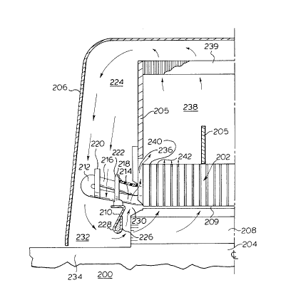
The application of the present invention will be found in
Figure 4 where a series air flow is shown in the salient pole
motor. Referring now to Figure 4, a motor 200 is illustrated
having a stator core 202 and rotor 204 supported in stator frame
205 (only partially shown). The motor is housed in housing 206
(only a part of which is shown) to enclose stator core 202 and
rotor 204 and provide a suitable circulating paths for the cooling
air. Rotor 204 is supplied with a set of poles 208 as in previous
figures for providing the rotating magnetic flux from the rotor 204.
o Again, an air gap 209 is present between the stator 202 and rotor
poles 208. In this instance, motor 200 is shown having a re-
circ~ ting ventilation system ~ltili7in~ heat exchanger 239.
The stator 202 is quite similar to the machine illustrated in
Figure 3, with the exception of shield or shroud shown at 210
which is secured to the end turns 212 at their inner legs 214. A
band 218 encircles the outer legs 216. A pair of bracing rings 220
and 222 are provided for radial support of the end turns 212. The
band 218 and support ring 222 essentially form a chamber around
the end turns for the isolation of the end turns inside ring 222 from
air entering inlet 224.
The shroud 210 is sealingly secured to the inside of bracing
ring 222 by means of a suitable sealant material. The shroud has
a wall section 226 which is formed into a tubular section 228.
The interior of tubular portion 228 may be filled with a suitable
21~7197
- 14 - GECAN3028
filler material to provide the necessary stiffness to the interior of
the shroud. Such a material would be a foamed polystyrene or a
foamed polyurethane. The essential feature of the invention is
that an interior chamber 230 is formed by shroud 210, end ring
222, band 218 which is essentially isolated from air entering duct
224 and the chamber 232 adjacent shaft 234 of rotor 204.
The stator core 202 is constructed in a similar manrler to
previously shown stator cores, with pockets of l~rnin~tions
forming ventilation slots therein. A duct 236 in the stator end
o frame 205 adjacent the end legs 214 and 216 provides for air flow
between the chamber 230 and chamber 238 surrounding the stator
core 202.
The operation of the ventilation of machine 200 is as
follows:
Rotor 204 provides the pumping action to motivate the air
flow through the machine in a similar manner to the rotor 102 of
Figure 3. Air enters the housing at duct 224 and passes through
and around the outward ends of coil end heads 212 to cool the
surfaces thereof. Air also passes between bracing rings 220 and
222 to cool the sections of end coils 212 located between these
rings. Air passes into the spaces between the rotor poles 208 by
passing around the tubular portion 228 of shroud 210 and is
compressed by the rotating rotor poles 208. Because shield 210
2147197
- 15 - GECAN3028
provides isolation of the chamber 230 so formed from
atmospheric pressure, the air pressure formed in the air gap
pressurizes into the chamber 230. Because of the limited
clearance between the ends of poles 208 and shield 210, a crude
seal is formed by the rotating rotor poles and the shield 210.
The increase in air pressure in the region 230 produces
more desirable air flow in the stator ducts at the remote ends of
the stator core 202. For instance, the air flow through duct 236
will be substantially increased over the air flow in the
o corresponding duct of the motor 100 in Figure 3 The air flow in
the outer stator ducts such as 240, 242 will be substantially
increased over the prior art motor of Figure 3.
The pressure profile is shown in Figure 4A. The pressure
profile shows that with the presence of shroud 210, the pressure
profile across the air gap is somewhat more equalized so that the
ventilation spaces in the stator near the ends carry significantly
more cooling air than the prior art machines. The cooling
eff1ciency of the machine is increased by the pressure eqll~li7~tion
provided by the shield 210 and the elimin~tion of lossy vortexes
created at the ends of the rotor when the shield is absent.
The advantages become obvious; the increased cooling
improves the rating or life of the machine 200. The machine may
be shortened because of the lack of bulky chambers for directing
2147197
.,
- 16 - GECAN3028
air flow in the ends of the machine. The end coils are cooled by
air passing in two directions over their surface. The rotor as
previously is able to be shortened and the resultant stiffness may
improve the operation of the rotor 204 in motor 200. Lastly, the
motor will operate with equal cooling efficiency while rotating in
either direction.
An alternative construction for the machine of Figure 4 is
shown in Figure 5. The salient pole motor 300 shown in cross-
section in Figure S includes a method of l1tili7.ing the present
o invention in a parallel air flow path ventilation system in a re-
circulating system with an associated heat exchanger.
The motor 300 has a stator core 302 and rotor 304 on
which the salient poles 308 are mounted. The shield 310 is
mounted in the same region as previously on the end coils 312 in a
sealed relationship. More particularly, the shield is securely
fastened to the inner coil legs 314 but the spaces between the coil
legs must be completely sealed as in such a manner as shown in
U.S. Patent 4,442,371 issued April 10, 1984, the same sealing
technique may be used on motor 200 of Figure 4.
~0 Shield 318 is mounted on bracing ring 322 which with
bracing ring 320 stabilizes the end coils of the machine outside the
stator. Shield 318 must seal to the stator end frame at 319 to
prevent escape of cooling air from this joint. Air enters housing
2147197
-
- 17 - GECAN3028
306 at duct 324 and passes over the remote ends of coil end heads
312 as the air moves inwardly toward the shaft 334. Thus, the
remote ends of coils such as 312 are cooled by the cool air
entering the machine. As the air passes through chamber 332, it
bends around the lip 328 of shield 310 and enters the spaces
between salient poles 308 and into space 330.
The air is compressed by the rotation of rotor poles 308 and
passes into the air gap and thence into the ventilation slots such as
340 and 342 of stator 302. Air will be driven from the end of the
o pole pieces adjacent shield 310 to compress the air in chamber
330. As previously, the shield 310 prevents the swirling vortex in
the region 330 when the shield 310 is not present. The cooling air
thus passes upwardly (outwardly) past the inner portions of coil
legs 314 and 316 to remove heat from the surfaces thereof. The
cooling air continues to move into space 344 and thence through
apertures such as 346 in the stator end frame into plenum 338 and
thence to heat exchanger 339 (or to atmosphere). The advantages
of the system are immediately obvious. The end coils are cooled
by the air passing over the coil legs in two different directions, but
air is partially diverted into duct 336 to provide cooling in stator
ends as previously. The pressure profile across the machine is
found in Figure 5A.
As expected, the pressure in chamber 332 is slightly
negative and as the air passes lip 328 of shield 310, the pressure
2147197
- 18 - GECAN3028
begins to increase because of the presence of the shield 310. The
pressure continues to increase along the air gap to a maximum at
the center of the machine.
The significance of this design is improved cooling of the
end coils of the machine over prior art machines and increased
cooling of the outward ventilation spaces 340 and 342 over the
prior art machines lacking the shield 310.
Thus, the machine of Figure 5, although a parallel air flow
type machine, may be kept compact by the elimin~tion of
o chambers such as 78 of Figure 2 which require substantial space.
Thus, a substantial reduction in material results and the rotor may
be stiffened as previously in Figure 4. The machine is able to
function without a fan such as 96 in Figure 1, thus, the efficiency
of the machine is increased.
The presence of the shield 310 prevents the establishment
of the vortex in the area 330, the presence of which represents a
loss in the operation of the machine. Thus, it can be seen that the
presence of a shield at the end of the stator which isolates the
rotor bore in such a manner as to permit the build up of pressure
on the rotor side of the shield permits more uniform air flow
through the stator ventilation spaces and prevents the
establishment of air vortices at the extended air gap of the motor.
The shield should extend inwardly to about the mid-point of
2147197
- 19- GECAN3028
the height of the salient poles as best shown in Figures 4 and 5.
The axial distance between the shield and the end of the rotor
poles should be in the order of pole hei~ht but physical constraints
present in the motor construction may dictate the limits in the
location of a shield at the stator ends of the machine.
The presence of the shields at the stator ends of the above
machines is responsible for more uniform air flow through the
stator ventilation ducts, and in addition, will provide a substantial
o increase in the total quantity of cooling air flowing through the
machine, probably yielding an increase of between 5 - 10% net air
flow.
It is believed that this invention provides a basic
improvement to the operation of a dynamo electric machine, and
the presence of an energy saving device such as the efficiency
shield will be a welcomed improvement in locations where the
cost of energy a burden.
While the invention has been described in conjunction with
specific embodiments, it is to be understood that many
alternatives, modifications and variations will be apparent to those
skilled in the art in the light of the foregoing description. The
composition of the shield would typically be of a non-magnetic
material such as a fiberglass reinforced plastic type of material to
avoid problems with induced currents. Because the air pressure
2147197
- 20 - GECAN3028
forces are quite modest, it will be possible to construct the shield
such as 310 in segments to facilitate assembly. However, the
invention is intended to embrace all alternatives, modification and
variations which fall within the spirit and scope of the appended
claims.