Language selection

Search

Patent 2147297 Summary

Third-party information liability

Some of the information on this Web page has been provided by external sources. The Government of Canada is not responsible for the accuracy, reliability or currency of the information supplied by external sources. Users wishing to rely upon this information should consult directly with the source of the information. Content provided by external sources is not subject to official languages, privacy and accessibility requirements.

Claims and Abstract availability

Any discrepancies in the text and image of the Claims and Abstract are due to differing posting times. Text of the Claims and Abstract are posted:

  • At the time the application is open to public inspection;
  • At the time of issue of the patent (grant).
(12) Patent Application: (11) CA 2147297
(54) English Title: VENTILATEUR DE TOITS
(54) French Title: ROOF VENTILATOR
Status: Dead
Bibliographic Data
(51) International Patent Classification (IPC):
  • F24F 7/02 (2006.01)
  • F24F 13/22 (2006.01)
(72) Inventors :
  • RHEAULT, ANDRE (Canada)
  • PROULX, GUY (Canada)
(73) Owners :
  • RHEAULT, ANDRE (Canada)
  • PROULX, GUY (Not Available)
(71) Applicants :
  • RHEAULT, ANDRE (Canada)
  • PROULX, GUY (Not Available)
(74) Agent:
(74) Associate agent:
(45) Issued:
(22) Filed Date: 1995-04-19
(41) Open to Public Inspection: 1996-10-20
Examination requested: 1995-07-25
Availability of licence: N/A
(25) Language of filing: English

Patent Cooperation Treaty (PCT): No

(30) Application Priority Data: None

Abstracts

English Abstract


This static ventilator is made with three parts: 1) a hollow
housing, triangular shaped with circumferential sidewalls and
louvers attached to the outside walls, 2) a triangular shaped base
fixed to the roof and 3) a cap at the top.

The hollow housing is the part that actually does the
ventilation. Each of its louvers is inclined downwards and out and
comes with a piece of filter material preventing anything from
entering the vent openings and allowing the air to circulate.

The triangular shape of the hollow housing allows the wind to
slide laterally along each side of the ventilator and prevents any
snow or debris accumulation at the base and on the louvers of the
ventilator.

In order to secure the hollow housing to the roof surface, a
triangular shaped piece serves as a base where the hollow housing
is inserted. This base also lets the condensed water flow out of
the hollow housing.

The cap seals the hollow housing and prevents anything from
falling straight into the ventilator.


Claims

Note: Claims are shown in the official language in which they were submitted.


WHAT IS CLAIMED IS:

1- A static roof ventilator including:

a triangular-shaped hollow housing comprising a base and three
sidewalls, each sidewall supporting one or more louvers
inclined downward and outward which louvers are secured to the
inner L-shaped support and

a removable triangular-shaped part fastening the hollow
housing to a roof.

2- A static roof ventilator as claimed in claim 1 above where the
triangular-shaped part fastening the hollow housing to a roof
includes:

a triangular-shaped hollow base opened at the top and at the
bottom, with three sidewalls, which base slides into the
hollow housing and makes it stand securely in an upright
manner vertically and

a flange plate to fasten the hollow base to an inclined roof.

3- A static roof ventilator as claimed in claim 2 above where the
triangular-shaped hollow base once set into the hollow housing
securely has three base's sidewalls' edges inclined inward and
upward to let any condensed water out which could be forming
and running down the sidewalls of the hollow housing.

4- A static roof ventilator as claimed in claim 3 comprising a
triangular-shaped removable top cover fastened by screws to
the upper part of the hollow housing and exceeding it in order
to let the air go through hence preventing any condensation.


5- A static roof ventilator as claimed in claim 4 comprising also
a filter material made of glass fiber placed in each louver
and held on one side by the folded louver's edge and on the
other side by an outer L-shaped support welded to the inner L-
shaped support.

6- A static roof ventilator as claimed in claim 5 comprising one
or more louvers, each louver being welded to the outer L-
shaped support and placed in front of a vent slot where each
louver's slat is inclined downward and outward and includes a
flange at the edge extended underneath in order to hold the
filter material.

Description

Note: Descriptions are shown in the official language in which they were submitted.


21~7297


PURPOSE OF THE PROJECT


The present invention relates to a static roof ventilator.
The purpose for building this new product comes with a dissatisfac-
tion of the actual products on the market. The facts are hereby
explained.

FACTS ABOUT VENTILATORS

Roof ventilators are used to take the air out of the attic and
replace it by colder air from outside. Generally, a roof ventila-
tor is either mechanical or static. The mechanical type requires
maintenance et makes noise as the static ones, because of their
chimney effect, do not require any maintenance. The two types of
ventilator have clogging problems at the exits when a storm comes
due to the snow and/or ice accumulation. Also, snow and/or debris
can build up at the base; often rectangular. Condensation problems
can also occur along the inner walls damaging the interior of the
house.

SUMMARY OF THE INVENTION


The problems encountered on the market as we have just stated
could be resolved by a static triangular shaped ventilator with
louvers. Contrary to a rectangular shaped ventilator, it is the
triangular shape of the hollow housing (with its three sidewalls on
which each has one or more downward and outward louvers) that
allows the wind to slide laterally along each side of the ventila-
tor which improves the chimney effect and prevents any accumulation
of snow, ice or debris around the base or on the louvers.

Moreover, the triangular base fixed to the roof made to
receive the hollow housing vertically allows the condensed water to

~14~ q~


escape; therefore, condensation problems are eliminated.

Each louver also have a useful purpose. With a piece of
filter material, they prevent anything from entering the vent
opening.

DESCRIPTION OF T~E STATIC ROOF VENTILATOR'S DRAWINGS

1- Drawings

Fig. 1 is the front elevation view
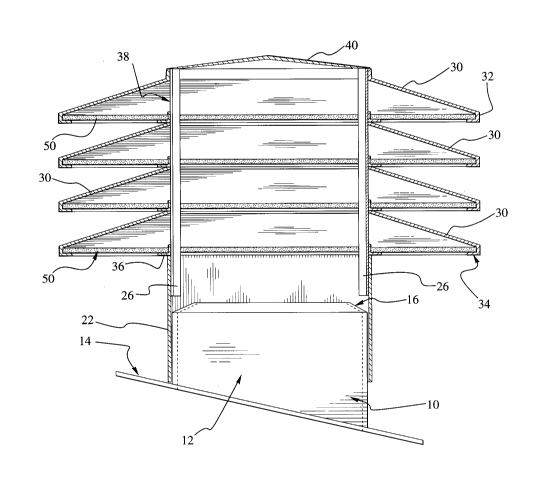
ig. 2 is a cross sectional view of Fig. 1 showing the inside of
the ventilator
Fig. 3 is a top view
ig. 4 is a view of a ventilator once installed on an inclined
roof

2- List of parts by numerical order

#10 Base
#12 Base's sidewalls
#14 Flange plate
#16 Edge of the base's sidewall
#20 Housing
#22 Housing's sidewalls
#26 Inner L-shaped support
#30 Louvers
#32 Louver's edge
#34 Louver's flange
#36 Outer L-shaped support
#38 Vent slots
#40 Top cover
#50 Filter material
#60 Static roof ventilator
A

21'~7~7


3- Detailed description of the static roof ventilator's elements


Fig. 2 drawing shows the static roof ventilator 60 made up of
a triangular shaped hollow base 10 which has three sidewalls 12
with their upper edge 16 inclined. The roof ventilator 60 is
nailed to the roof surface through the flange plate 14. The base
and top sections of the ventilator are opened at the top and
bottom.

The housing 20 is made of three sidewalls 22 each provided
with at least one louver 30. Fig. 2 shows four louvers. Each
louver 30 is spot welded to an inner L-shaped support 26 in turn
spot welded to the inner face of each housing's sidewalls 22. Each
louver is placed in front of a vent slot 38.

Each louver's flange 34 is folded horizontally under at the
edge 32 in order to support the detachable filter material 50. An
outer L-shaped support 36 welded to the inner L-shaped support 26
holds the other end of the filter material 50. This filter
material is made of glass fiber, washable, non-ahsorbant and
resistant. It lets the air flow through easily and is very
efficient against snow, bugs and/or dust.

A top cover 40 exceeds and is screwed to the upper part of the
hollow housing 20 lets the air circulate inside the ventilator 60
and prevents any condensation.

Fig. 4 shows the chimney effect of the roof ventilator 60
replacing the air coming from the attic with colder air from
outside flowing through the cornices.

Representative Drawing
A single figure which represents the drawing illustrating the invention.
Administrative Status

For a clearer understanding of the status of the application/patent presented on this page, the site Disclaimer , as well as the definitions for Patent , Administrative Status , Maintenance Fee  and Payment History  should be consulted.

Administrative Status

Title Date
Forecasted Issue Date Unavailable
(22) Filed 1995-04-19
Examination Requested 1995-07-25
(41) Open to Public Inspection 1996-10-20
Dead Application 1998-04-20

Abandonment History

Abandonment Date Reason Reinstatement Date
1997-04-21 FAILURE TO PAY APPLICATION MAINTENANCE FEE

Payment History

Fee Type Anniversary Year Due Date Amount Paid Paid Date
Application Fee $0.00 1995-04-19
Owners on Record

Note: Records showing the ownership history in alphabetical order.

Current Owners on Record
RHEAULT, ANDRE
PROULX, GUY
Past Owners on Record
None
Past Owners that do not appear in the "Owners on Record" listing will appear in other documentation within the application.
Documents

To view selected files, please enter reCAPTCHA code :


To view images, click a link in the Document Description column. To download the documents, select one or more checkboxes in the first column and then click the "Download Selected in PDF format (Zip Archive)" or the "Download Selected as Single PDF" button.

List of published and non-published patent-specific documents on the CPD .

If you have any difficulty accessing content, you can call the Client Service Centre at 1-866-997-1936 or send them an e-mail at CIPO Client Service Centre.


Document
Description 
Date
(yyyy-mm-dd) 
Number of pages   Size of Image (KB) 
Drawings 1996-10-20 2 50
Cover Page 1996-11-13 1 14
Abstract 1996-10-20 1 57
Description 1996-10-20 3 94
Claims 1996-10-20 2 48
Representative Drawing 2000-04-06 1 26
Examiner Requisition 1996-08-16 2 88
Examiner Requisition 1995-11-21 2 74
Office Letter 1995-09-08 1 23
Prosecution Correspondence 1995-07-25 2 47
Prosecution Correspondence 1995-12-08 4 106
Office Letter 1996-05-06 1 15
PCT Correspondence 1996-04-01 1 28
Prosecution Correspondence 1995-05-24 1 25
Office Letter 1995-05-11 2 68