Note: Descriptions are shown in the official language in which they were submitted.
214'303
MULTILAYER STRRTCH/SHRINK FILM
Field of the Invention
This invention relates to an improved biaxially
oriented heat shrinkable multilayer film, a hermetically
sealed and evacuated trayed food package wherein the film
is used as a stretched heat shrunk overwrap and a method
for sealing and wrapping such packages.
Background of thg invention
For many years, food products such as fresh
poultry were shipped in bulk from the food processors to
supermarkets where the bulk pieces were divided into
small quantities and repackaged for retailing. For
example, fresh poultry was cut up, placed on cardboard or
plastic trays, and covered with stretch film secured to
the tray by tack welding.
For improved efficiency the current trend is to
perform the retail packaging operation in the food
processing plant and ship the small retail packages from
such plants to the retailers. There is also a trend
towards evacuating and hermetically sealing the food
retail packages in the central food processing plants,
due to the longer storage time between retail packaging
and consumer use. Such packaging increases the shelf
life of the food packages. Also, there is a need for
increased abuse resistant food retail packages because of
the more frequent handling, impact and abrasion inherent
in the above-described food processing plant retail
packaging system.
~-iotbt
_t_
217303
This retail packaging can be accomplished in a
variety of ways. A number of systems are available to
food processors for wrapping and heat sealing poultry-
containing trays with plastic overwrap film. One
packaging system that uses a continuous belt sealer is
the Ossid"' 500, produced by the Ossid Corporation.
(Ossid''" is a trademark of the Ossid Corporation, North
Carolina, USA.) Generally, a poultry-containing tray is
moved by a series of conveyors and rolls while a film is
fed from a dispenser and mechanically pulled over the
tray top. The film edges are wrapped around the tray,
pressed against the tray bottom, overlapped and sealed
against it. Finally, the tray is moved forward and the
opposite ends cut. In the OssidT" 500 system both cut
portions of the film, the flaps, are pulled under the
tray and shaped under the tray.
Sealing is done with heat and pressure. In
impulse sealing systems, the contact temperature ranges
from about 400 to 800°F with a high applied pressure due
to the narrow sealing surface. In a bar heating sealing
system, the temperature ranges from 250 to 400°F with a
similar pressure as above. The heat contact time is
longer than with the impulse system. The Ossid 500
employs a continuous belt sealer that consists of a
release belt that is drawn over a heated platen. The
resultant platen seal has characteristics that vary
significantly from other commercial sealing processes.
In the platen heating-sealing system, the temperature is
at about 250 to 400°F, using a low pressure of about 0.1
to 2.0 psi, with the heat contact time being 2 to 4
seconds.
The wrapped tray is passed to the belt or
platen which applies heat that bonds the film layers
together and, upon cooling, the seal is fixed. The heat
bonded film is then immediately cooled to a temperature
below about 200°F.
D-20161
247303
The machinability of the film, or the way that
it operates on the machine, is an important
characteristic of the film used.
The most commonly used film in the trayed food
overwrap market is polyvinyl chloride (PVC). This
thermoplastic polymer has been used because of
satisfactory elongation and elastic memory. But in some
instances the package becomes leaky during shipment and
thereby unacceptable to the customer. This is because
the PVC material in overwrapped trays is tack welded to
itself and not hermetically sealed. This problem cannot
be solved by hermetically sealing because of a very
narrow sealing temperature range between which the seal
is effective at the low temperature end and "burn
through" or melting of the PVC at the high temperature
end. This range is so limited as to be impractical with
many commercially employed heat sealing systems.
Another limitation of PVC tray overwrap
material is its poor resistance to physical abuse. The
PVC material tends to tear along the edges of the
overwrapped tray if rubbed during transit by another tray
or an enclosing carton.
One characteristic of PVC is that although it
contracts, it is not generally "heat-shrinkable", i.e.,
it is a material that tends not to return to its original
unstretched (unextended) dimension when heated to its
softening point. The terms "orientation" or "oriented"
are used to describe the manufacture of heat-shrinkable
films, wherein resin material is heated to its flow or
melting point and extruded through a die into either
tubular or sheet form. After cooling, the relatively
thick extrudate is reheated to a temperature range
suitable to orient or align the crystallites and/or
molecules of the. material. The orientation temperature
range for a given material or materials is understood by
those skilled in the art to be in a range which revises y
the intermolecular configuration of the material by
D-20161
CA 02147303 1999-04-27
physical alignment of the crystallites and/or molecules
of the material to improve certain mechanical properties
of the film such as shrink tension as, for example,
measured in accordance with ASTM D-2838-81. When the
stretching force is applied in one direction, uniaxial
orientation results. When the stretching force is
simultaneously applied in two directions, biaxial
orientation results.
In view of the limitations of PVC as a stretch
film food tray overwrap material, there have been prior
efforts to identify a heat-shrinkable thermoplastic film
having an improved combination of elongation, elastic
memory, heat sealability and puncture resistance.
However, most heat-shrinkable thermoplastic film
packaging materials suitable for food contact have
relatively poor elasticity or elastic memory. Thus, when
a food wrapped in such a material shrinks from moisture
loss, the film does not shrink, resulting in a loose
package that is unacceptable.
One PVC replacement film for use as a trayed
food overwrap material is described in U.S. Patents
5,272,016 and 5,279,872, issued to D.J. Ralph ("Ralph").
The Ralph film is the biaxially oriented heat-shrinkable
multilayer stretch type, comprising at least a first
2~ outer layer, a second outer layer, and a core layer
between the first and second outer layers. The outer
layers each comprise a blend of between about 20 and
about 35 wt.% ("wt.%") ethylene a-olefin plastomer
copolymer of density below about 0.90 g/cm', and between
about 65 and about 80 wt.% ver low densit
y y polyethylene
("VLDPE"). The core layer comprises ethylene a-olefin
copolymer having a higher melting point than the melting
points) of either of the first or second outer layers.
By way of example, the core layer may be polypropylene or
a polyolefin. Embodiments of the latter include VLDPE,
-4 -
2147303
linear low density polyethylene ("LLDPE"), and blends of
two different density VLDPE's or VLDPE and LLDPE.
The Ralph-type film in nonirradiated form has
been demonstrated to be suitable as a PVC replacement for
food tray overwrapping and sealing by the impulse and bar
heating-sealing systems. However, it has substantial
limitations when used in platen sealing systems.
When the heat seal between the film layers
forming the end flaps is not complete, the package is
defective. Incomplete seals represent potential
air/fluid leaks and loss of food quality and/or desired
appearance in the retail market. As seen from the above,
the number of overlapping film layers to be sealed
together may vary substantially, generally from six to at
least twenty. This means that the required maximum seal
temperature must be relatively high, because as the
number of film layers increases, the temperature at a
given residence time required for a complete seal
increases. However, "burn through" places an upper
limit on the sealing temperature. Burn through means the
temperature at which any hole or penetration of the film
I~ occurs, resulting from melting and/or shrinking of the
film during sealing.
When the Ralph-type film with a 100% VLDPE core
layer was tested for use on platen sealed pcultry-
containing trays, the sealing range was too narrow as
complete sealing could not be obtained without burn
f;~
through. In an attempt to overcome this problem, LLDPE
was added to the core layer making the core a VLDPE-LLDPE ,
blend. This formulation provided a broad enough platen
seal range on an Ossid 500 system under ideal conditions,
but under production conditions the sealing range was
still too narrow. To broaden the heat sealing range of
the VLDPE-LLDPE blend core layer Ralph-type film, the
film was irradiated at a dose of 8 MR after biaxial
orientation.
D-20161 's-
21'7303
Although irradiation of the VLDPE-LLDPE blend
core layer Ralph-type film provided the needed wide heat
sealing range, a new and unexpected problem developed.
The film had poor machinability. The slide
characteristics of the film were such that the film could
not be smoothly transported through and over the various
belts and rollers which are essential to film movement
through the wrapping machine. At the same time, it
should be recognized that the film cannot be so
frictionless that it cannot be secured by the clamps as,
for example, chain grips, which grab the film edges and
pull it taut over the top of the tray.
During testing, another facet of the
machinability problem with the irradiated Ralph-type
film, flap pull back, was discovered. Flap pull back
refers to the tendency for the folded under flap to be
pulled away from the tray bottom surface by movement
across the rollers prior to entering the platen sealer-
cooler. This problem appears to be related to the
frictional properties of the film, possibly the ratio of
the friction between the flap folding rollers on the
platen sealing-cooling system and the film-to-film slip.
An improved polyolefin-type heat-shrinkable
oriented stretch film suitable for use as a platen heat
sealed overwrap material for a food tray with a wide
sealing range and good machinability is needed. This
film should also be characterized by good elongation, '
good elastic memory, puncture resistance and abrasion .
resistance.
An improved method for wrapping and platen- .
sealing a polyolefin stretch-shrink film as an overwrap
on a food-containing tray is also needed.
Also needed is an improved evacuated w
hermetically sealed food-containing tray overwrapped by a
heat shrunk polyolefin film.
D-20161 -~'
CA 02147303 1999-04-27
Brief Description of the Invention
An improved polyolefin-type heat shrinkable
oriented stretch film suitable for use as a overwrap
material for a food tray that is platen heat sealed on an
automated system has been invented. This film is
characterized by good elongation, good elastic memory,
puncture resistance and abrasion resistance. It also has
a wide sealing range and good machinability, especially
in the platen-type heat sealing system.
One aspect of this invention relates to a
crosslinked biaxially oriented heat shrinkable multilayer
stretch film comprising at least one outer layer, a
second outer layer and a core layer between the first and
second outer layers. The outer layers each comprise a
two component polyethylene blend of between about 25 and
about 75 wt.% VLDPE of density between about 0.900 and
about 0.914 g/cm3, and between about 25 and about 75 wt.%
LLDPE of melt index below about 3.5 g/10 minutes and
density between about 0.917 and about 0.925 g/cm3. The
LLDPE comprises less than about 35 wt.% of the total film
weight.
The core layer of this film comprises a three
component blend of between about 40 and about 75 wt.%
first VLDPE having a density between about 0.905 and
2~ about 0.914 g/cm3, between about 10 and about 35 wt.%
second VLDPE of density between about 0.900 and about
0.905 g/cm3, and between about 15 and about 35 wt.%
ethylene a-olefin plastomer copolymer with a density
below about 0.900 g/cm3. In this film, the core layer
has a lower composite melting point than do the outer
layers.
In accordance with an aspect of the present
invention there is provided a crosslinked biaxially
oriented heat shrinkable multilayer stretch film which
comprises at least a first outer layer, a second outer
layer and a core layer between the first and second outer
layers, the first and second outer layers each comprise
CA 02147303 1999-04-27
a two component polyethylene blend of between 25 and 75
wt.a very low density polyethylene ("VLDPE") of density
between 0.900 and 0.914 g/cm3, and between 25 and 75 wt.%
linear low density polyethylene ("LLDPE") of melt index
below about 3.5 g/10 minutes and density between 0.917
and 0.925 g/cm3, the LLDPE which comprises less than about
35 wt.% of the total film weight; and the core layer
which comprises a three component blend of between 40 and
75 wt.o first VLDPE of density between 0.905 and 0.914
g/cm3, between 10 and 35 wt.% second VLDPE of density
between 0.900 and 0.905 g/cm3, and between 15 and 35 wt.%
ethylene a-olefin plastomer copolymer of density below
0.900 g/cm3, the film being heat shrinkable and being
crosslinked such that when subjected to the Platen Test
on a plate heated to a contact surface temperature range
between 280°F and 400°F for a contact time of between 2
and 4 seconds, the film heat seals and does not burn
through.
The film of this invention has biaxial heat
shrink properties and is crosslinked such that when
subjected to the Platen Test (described below) on a plate
heated to a contact surface temperature range between
about 280°F and about 400°F, for a contact time of
between about 2 and about 4 seconds, the film heat seals
30
40
-7a-
CA 02147303 1999-04-27
and does not burn through. Heat shrinkable means that
the film has at least loo free shrink at 90°C measured in
both the machine and transverse directions in accordance
with ASTM D-2732.
Another aspect of the invention relates to a
hermetically sealed and evacuated food package which
comprises a tray with a bottom section surrounded by
upwardly extending side and end walls, perishable food
supported on the upper surface of the bottom section, and
a stretched heat shrunk film extended over the food, the
upper edges of the side walls and at least part of the
lower surface of the tray bottom section and heat sealed
to itself in flattened relationship against the lower
surface so as to form with the tray a hermetically sealed
enclosure for the food. In this aspect of the invention,
the improvement is the biaxially oriented multilayer
composition as the stretched heat shrunk film described
in the paragraphs above.
In accordance with yet another aspect of the
present invention there is provided in a hermetically
sealed and evacuated food package which comprises a tray
with a bottom section surrounded by upwardly extending
side and end walls, perishable food supported on the
upper surface of the tray bottom section, and a stretched
heat shrunk film extending over each of the food, the
side and end wall upper edges and at least part of the
lower surface of the tray bottom section and heat sealed
to itself in flattened relationship against the lower
surface; the improvement which comprises as the film a
crosslinked biaxially oriented heat shrinkable multilayer
stretch film which comprises at least a first outer
layer, a second outer layer and a core layer between the
first and second outer layers, the first and second outer
layers each comprise a two component polyethylene blend
of between 25 and 75 wt.% VLDPE of density between 0.900
and 0.914 g/cm3, and between 25 and 75 wt.o LLDPE of melt
index below 3.5 g/10 minutes and density between 0.917
_g_
CA 02147303 1999-04-27
and 0.925 g/cmj, the LLDPE which comprises less than 35
wt.o of the total film weight; and the core layer which
comprises a three component blend of between 40 and 75
wt.o first VLDPE of density between about 0.905 and 0.914
g/cm3, between 10 and 35 wt.% second VLDPE of density
between 0.900 and 0.905 g/cm3, and between 15 and 35 wt.%
ethylene a-olefin plastomer copolymer of density below
0.900 g/cm3, the film having original biaxial heat shrink
properties and being crosslinked such that when subjected
to the Platen Test on a plate heated to a contact surface
temperature range between 280°F and 400°F for a contact
time of between 2 and 4 seconds, the film heat seals and
does not burn through.
Still according to another aspect of the
present invention there is provided a process for platen
heat sealing the overlying folded ends of multiple
contiguous layers of a stretched thermoplastic film
covering a food-containing tray having side and end walls
upwardly extending from a bottom section wherein the
multiple layers of film are folded over the tray end
walls, pressed against the lower surface of the tray
bottom section and interlayer heat bonded together to
form a hermetically sealed and evacuated food package.
The improvement comprises using as the thermoplastic film
the above described at least three layer film article,
providing a flat metal plate with a release surface as
the platen surface, heating the upper surface of the
plate to temperature between about 250 and 400°F,
contacting pressed folded end portions of the stretched
film cover with the heated metal plate for a period of
between about 2 and about 4 seconds so as to bond the
contiguous film layers of the folded end portions
together without burn through of the film, and
-8a-
CA 02147303 1999-11-03
thereafter immediately cooling the heat bonded end
portions of said film to temperature below about 200°F.
According to a further object of an aspect of
the present invention is the use of a crosslinked
biaxially oriented heat shrinkable multilayer stretch
film comprising at least a first outer layer, a second
outer layer and a core layer between the first and second
outer layers, the first and second outer layers each
comprising a two component polyethylene blend of between
25 and 75 wt.% VLDPE of density between 0.900 and 0.914
g/cm3, and between 25 and 75 wt.% LLDPE of melt index
below 3.5 g/10 minutes and density between 0.917 and
0.925 g/cm3, said LLDPE comprising less than 35 wt.% of
the total film weight; and the core layer comprising a
three component blend of between 40 and 75 wt.% first
VLDPE of density between 0.905 and 0.914 g/cm3, between 10
and 35 wt.% second VLDPE of density between 0.900 and
0.905 g/cm3, and between 15 and 35 wt.% ethylene a-olefin
plastomer copolymer of density below 0.900 g/cm3, the film
being heat shrinkable and being crosslinked such that
when subjected to a Platen Test on a plate heated to a
contact surface temperature range between 280°F and 400°F
for a contact time of between 2 and 4 seconds, the film
heat seals and does not burn through in a process for
platen heat sealing the overlying folded ends of multiple
contiguous layers of a stretched thermoplastic film
covering a food-containing tray having side and end walls
upwardly extending from a bottom section wherein the
multiple layers of film are folded over the tray end
walls, pressed against the lower surface of the tray
bottom section and interlayer heat bonded together to
9
CA 02147303 1999-11-03
form a hermetically sealed and evacuated food package,
wherein the process comprises providing the film;
providing a flat metal plate as the platen surface;
heating the upper surface of the plate to temperature
between 300 and 400°F; contacting downwardly and inwardly
Brief Descriotionof the Drawings
Figure 1 is a cross-sectional view of the flap
folding mechanism.
Figure 2 is a cross-sectional elevation view of
a sealer-cooler system.
Detailed Description of the Invention
In the food industry and, in particular in the
poultry industry, small quantities of poultry are cut up
and packaged in trays which are overwrapped with film.
This packaging allows retail sized quantities of food to
be prepackaged by the food plant and shipped to retail
outlets in a condition acceptable to both the health
department authorities, the retailer and the final
consumer.
The various film-shaping steps in a .
representative method for covering a food-containing open
tray with a stretch-shrink film using the hot platen
sealing system is described below. Each of the following
steps is performed automatically on an overwrap system,
in particular, the Ossid~ 500, starting with a tray of
food or, particularly, poultry.
Food containing open trays are longitudinally
spaced and moved forward on a feed conveyor belt. The
feed belt is supported at opposite ends by rolls and
moves continuously to carry trays to a position beneath a
film roll dispersing system positioned above the conveyor
belt. When a sensor detects the presence of the food
containing tray beneath the feed roll system, film is
then dispensed from the supply roll through a series of
guide and tensioning rolls as will be understood by those
skilled in the art. The dispensed and tensioned film is
seized and stretched by a series of clamps as, for
9a
2~4'~3~3
example, chain grips longitudinally aligned on opposite
sides of the dispensed film edges at progressively
increasing distances from the longitudinal centerline of
the system in the direction of the film movement.
Downwardly moving clamps grab the films outer edges and
progressively pull the film tautly over the top edges of
tray sides. There are two points in the chain gripping
system where problems can occur with the wrong type of
film: the film can be either too slippery for the clamps
to correctly grasp it, or not slippery enough so that the
film does not dispense easily and therefore jams up in
the dispensing system.
The clamps are activated by cams at each end of .
chain grip belt to grab and release the tensioned film at
respective opposite ends of the belt. Upon release from
the grip clamps, the film is pulled under the tray by
plates and center rollers. The two edges of the film are
overlapped and can be longitudinally sealed together by
heated rollers. The tubular film-enclosed tray is driven y
forward by belt conveyor having flexible, eg.,
elastomeric contact surfaces including side walls. The
transverse distance of these side walls from the
longitudinal centerline can be adjusted depending on the
tray size and film thickness.
After the tube film longitudinal center seal is
completed, the opposite ends are cut by knives. Next,
the cut portion of the tube film extending in front of
the tray (ie., the front flap) is pulled under the tray
by a roller-vacuum system. Flap guides are located on
each side of the tray to help shape the front flap so
that it does not extend beyond the bottom edges of the
tray. At this point in the film packaging system, the
front end film has been stretched over and under the tray -.
front end against the tray bottom and towards the tray
rear end. The flap folding areas of the machine are also
areas where film with incorrect frictional properties
will jam up the overwrap process.
D- 2 0161 -~a -
2147303
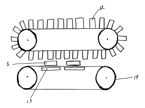
As shown in Figure 1, the partially film 5
enclosed food-containing tray 1 then passes over the rear
films flap folding conveyor 2 which, for example, may
comprise a series of plastic rollers 3 with a leading
metal roller 4. The latter is longitudinally spaced from
the next forward roller to provide a gap. The trailing
flap 6 is pulled with this gap by a mechanically applied
vacuum system. The rollers 3, which are moving faster
than the tray 1, flatten the trailing flap 6 under the
tray 1 to form the food package.
As the rear flap is being folded under, the
front flap can be pulled out. If frictional forces are
higher between the film and the metal roller of the flap
folding area than between the film and itself, the front
flap is pulled out. If the front flap is not completely
sealed, the whole package must be reworked.
The stretch wrapped food package is now moved
to the sealer system.
As seen in Figure 2, the bottom surfaces of
foam pillows 12 in the sealer system are in direct
contact with the wrapped food package 1 to apply uniform
pressure to insure efficient heat transfer by solid
conduction from the heated metal platen 13 to the film
end folds pressed against the bottom outer surface of the
tray 1. Heat is applied by a heating means, eg.,
electric resistance or circulating fluid. A
representative temperature range for the heated platen
top surface in the practice of this invention is 300-
400°F. Based on a belt sealer conveyor 14 speed of about
50 ft/minute and a 40" long heating platen 13, the tray-
platen contact time is about 2 - 4 seconds.
After heat sealing the flap ends to themselves '
as supported by the food package bottom surface, the food
package is conveyed to a cooling platen 15 that is
cooled. The top surface of the platen may be cooled to
about 55-65°F and is in contact with the tray 1 for a
D-20161 _»_
2I4'~30~
sufficient amount of time to cool the heated film below
200F. .
If the film used to overwrap the food trays has
the wrong machinability qualities, the trays will not be
usable. The film must be slippery enough to slide though
the overwrap machine without jamming, but must be able to
be held tautly in place when being stretched over the
food and maintain this tautness until sealed. It must
allow the trays to continue their forward movement on the v
conveyor belt once the flaps have been folded under. And
finally, it must be able to be completely heat sealed
without burning through the layers of film. ..
The polyolefin multilayer film of this
invention requires at least three layers, two outer
layers and a core layer between the outer layers, has
biaxial heat shrink properties and is crosslinked.
Stretch recovery and abrasion resistance of the film
meets the requirements of the food packaging industry.
It exhibits good machinability, overcomes the problems
associated with an irradiated Ralph film, has adequate
slip properties, is resistant to burn through and has no
flap pull back.
The film of this invention is a crosslinked
biaxially oriented heat shrinkable multilayer stretch
film comprising at least one outer layer, a second outer
layer and a core layer between the first and second outer
layers. The outer layers each comprise a two component
polyethylene blend of between about 25 and about 75 wt.%
VLDPE of density between about 0.900 and about 0.914
g/cm3, and between about 25 and about 75 wt.% LLDPE of
melt index below about 3.5 g/10 minutes and density
between about 0.917 and about 0.925 g/cm3. The LLDPE
comprises less than about 35 wt.% of the total film
weight. A preferable range of components is from about
30 to about 40 wt.% of VLDPE and from about 60 to about
70 wt.% of LLDPE. Additives can comprise up to
approximately 10% of the final formulation.
D-20161 -u-
4, . , v, ' , I, .
. ' , . . :,
;~ ,
y '
. ~
.. ;
< .
,y
' '.
21~73U3
The core layer of this film comprises a three
component blend of between about 40 and about 75 wt.o
first VLDPE having a density between about 0.905 and
about 0.914 g/cm3, between about 10 and about 35 wt.o
second VLDPE of density between about 0.900 and about
0.905 g/cm3, and between about 15 and about 35 wt.o
ethylene a-olefin plastomer copolymer with a density
below about 0.900 g/cm3. A preferable range of
components is from about 60 to about 75 wt.o of the first
VLDPE, about 13 to about 20 wt.% of the second VLDPE and
about 15 to about 25 wt.% of the plastomer. Also, the
ratio of plastomer to second VLDPE should range from
about 0.77 to about 1.83, preferably from about 1.29 to
about 1.42. Additives can comprise up to about 3% of the
final formulation of the blend.
Polyolefins are hydrocarbon polymers derived
from a simple olefin, such as polyethylene or
polypropylene and copolymers of such olefins. Their
basic structure is characterized by the chain (CH2CH2}~
and they may be found as a homopolymer or as a copolymer.
Polyolefins used in the present invention, unless
otherwise noted, are substantially free of halogens,
oxygen or other elements apart from carbon and hydrogen,
except for incidental amounts, e.g., trace residues of
catalysts or process related contaminants of the above. ..
The outer layers are a two component
polyethylene blend of VLDPE and LLDPE, while the core
layer is a three component blend of two VLDPE's and a so-
called ethylene a-olefin °plastomer".
One type of polyethylene is known as Linear Low
Density Polyethylene ("LLDPE"). Only copolymers of
ethylene with a-olefins are in this group. LLDPEs are
presently recognized by those skilled in the art as
having densities from about 0.917 to about 0.940 g/cm3.
The a-olefin used is usually 1-butene, 1-hexene or 1-
octene. Ziegler-type catalysts are usually employed in
their production, although Phillips catalysts are also
D-20161 -i;
CA 02147303 1999-04-27
used to produce LLDPE having densities at the higher end
of the range. LLDPEs typically do not have many long
branches off the main chain.
Another form of linear polyethylene is Very Low
Density Polyethylene ("VLDPE"), also called Ultra Low
Density Polyethylene ("ULDPE"). The densities of
commercial VLDPEs are recognized by those skilled in the
art to range between about 0.890 and about 0.914 g/cm3.
VLDPEs comprise copolymers of ethylene with a-olefins,
usually 1-butene, 1-hexene or 1-octene, and in some
instances terpolymers, as, for example, of ethylene, 1-
butene and 1-octene. As used here, VLDPE also includes
terpolymers of ethylene and higher a-olefin comonomers.
A process for making VLDPE is described in
European Patent Document publication number 120,503,
As described in EP 120,503, these particular VLDPEs are
made by using the traditional Ziegler-Natta heterogeneous
catalyst system.
Alternatively, VLDPE and LLDPE may be prepared
by a homogeneous metallocene single-site catalyst system
which in general produces molecular chains of more
uniform lengths with more evenly spaced comonomer. This
type of system is described in U.S. Patent 5,183,867,
assigned to Exxon Chemical Company ("Exxon") and European
Patent Application Publication 0 416 815 A2, assigned to
Dow Chemical Company ("Dow"),
For example, as described in U.S. Patents
4,640,856 and 4,863,769, VLDPEs are useful in biaxially
oriented films which have superior properties to
comparable films using LLDPEs. These superior properties
include higher shrink, higher tensile strength and
greater puncture resistance.
Commercially available ethylene a-olefin
plastomers have densities typically below 0.900 g/cm3.
Examples of plastomers include the Japanese Mitsui
Corporation's ("Mitsui") "Tafmers". As used here,
-14 -
X147303
ethylene a-olefin plastomers include terpolymers of
ethylene and higher a-olefin comonomers. According to US
Patent 4,'469,753, Tafmers are copolymers of butene-1.
Although it appears that the Tafmer-type
plastomers are prepared using the Ziegler-Natta
heterogeneous catalyst systems, other ethylene a-olefin
plastomers are manufactured using homogeneous metallocene
single-site catalyst systems as previously described.
The following is a general discussion of LLDPE,
VLDPE and plastomer properties from several perspectives.
Crystallinity
Differential Scanning Colorimetry ("DSC") is
commonly used to measure the amount of crystallinity in a
plastic sample, while revealing the nature of this
crystallinity. As determined in a procedure similar to
ASTM D-3418, a DSC is performed by exposing a sample of
the plastic to a constant rate of heating, i.e., 50°C per
minute in a E.I. DuPont de Neumours Company ("DuPont")
brand differential scanning colorimeter. When the
temperature of a sample reaches the melting point of a
crystalline region, the continued application of heat
causes the crystalline fraction to melt, while the sample
temperature remains constant. After the crystalline
region has melted, the sample temperature once again
begins to rise.
DSC measurements were performed on two types of .
VLDPE's: the Union Carbide Corporations ("Union Carbide")
1137, an ethylene-butene copolymer with 0.906 g/cm3
density and the Dow Attane"' 4001, an ethylene-octene
copolymer with 0.912 g/cm3 density. The same type
measurement was performed with Tafmer A-1085. Each of
these ethylene a-olefin copolymers has some crystallinity
but the crystalline nature of the ethylene. a-olefin
plastomer and the VLDPE copolymers is entirely different.
The entire crystalline phase of the ethylene a
olefin Tafmer A-1085 plastomer melts between about
D-20161
247303
55 and 85C, and this melting point
range is consistent
with the crystalline phase being made of an ordered
up
butane-ethylene copolymer. In contrast,the VLDPE
copolymers useful in this invention at least one
have
crystalline phase with the dominant e being that of a
phas
higher temperature melting point, aboveabout 90C.
The melting points of representative
VLDPE,
LLDPE and plastomeric ethylene a-olefincopolymers useful '
in the practice of this invention are en in Table A.
se
Table A - Ethylene a-Olefin
Melting Points (C)
Type Compound and Manufacturer MP (C)
Dow 2045 LLDPE 121
Exxon 3 0 01 LLDPE 12 5 ~' ~
Exxon 3 2 01 LLDPE 12 6 ~' ~
Union Carbide 1137 VLDPE 117
Union Carbide 1085 VLDPE 117
Union Carbide 1092 VLDPE 121
Union Carbide 1063 VLDPE 124
Union Carbide 1064 VLDPE 125
Dow Attane" 4001 VLDPE 121
Dow Attane"' 4003 VLDPE 107/124(two
peaks)
Exxon Exact''" 3025 VLDPE 103~'~
Exxon Exact''" 3034 VLDPE 95~'~
Exxon Exact''" 3 03 3 VLDPE 94 ~' ~
Exxon Exact''' 3027 VLDPE 92~'~
Dow Affinity'" PL 1840 VLDPE 103
Dow Affinity"' PL 1880 VLDPE 100
Mitsui Tafmer A-4085 plastomer 71
Mitsui Tafmer A-4090 plastomer 85 '
Mitsui Tafmer A-1085 plastomer 71
Exxon Exact"' 4011 plastomer 66~'~
' ~ Exxon method
D- 2 0161 -t6
Z14'~303
Table A demonstrates the substantial difference
in melting points of VLDPE and LLDPE as compared to
ethylene a-olefin copolymer plastomers. More
particularly, ethylene a-olefin copolymer plastomers
suitable for use in this invention have melting points
below about 90°C and VLDPE and LLDPE materials suitable
for use in this invention have melting points above about
90°C. Preferably the plastomers have melting points
below about 85°C. Preferred VLDPE copolymers for
practice in this invention have a crystalline melting
point between about 92°C and about 125°C.
Vicat Softening Point
Vicat softening points as performed by ASTM
1525 are reported by the resin manufacturers and are
summarized in Table B (Vicat Softening Points).
Table B
Vicat Softening Points (°C)
Type Compound and Manufacturer °C
Dow 2045 LLDPE 100
Union Carbide 1137 VLDPE 80
Union Carbide 1063 VLDPE 93
Union Carbide 1064 VLDPE 90
Union Carbide 1569 VLDPE 94
Dow Attane'''° 4001 VLDPE 95
Dow Attane~' 4003 VLDPE 80
Dow Attane"' 4004 VLDPE 92
Exxon Exact"'3033 VLDPE 75-83
Mitsui TafmerA-1085 plastomer 58
Mitsui TafmerA-4085 plastomer 54
Mitsui TafmerA-4090 plastomer 65
Mitsui TafmerA-20090 plastomer 60
Mitsui TafmerA-0585 plastomer 62
Exxon Exact"4011 plastomer 70 .
D-2016 1 -~r-
2.47303
Based on the foregoing and for purposes of this
invention, LLDPE and VLDPE-type ethylene a-olefin
copolymers useful in the practice of this invention
preferably have Vicat softening points of at least about
75C, and most preferably between about 78C and about
100C. Conversely, preferred plastomer-type ethylene a-
olefin copolymers have Vicat softening points below about
72C and most preferably between about 50C and about
72C.
Molecular Weight/Size Distribution
Ethylene a-olefin copolymers may be partially
characterized by their weight average molecular weight
(Mw) which is determined by multiplying the weight of
each chain of a given number of repeat units by the
number of such chains and dividing by the total weight of
chains. Ethylene a-olefin copolymers may also be
partially characterized by a number average molecular
weight (Mn), which is derived from the total weight of
polymer molecules divided by the total number of
molecules. When both of these are known, they can be
used to characterize the shape of the molecular weight
distribution curve for the copolymer, i.e., the number of
polymer chains in a molecular weight interval as the
ordinate and the molecular weight as the abscissa.
A high Mw/Mn connotes a wide distribution of
molecular weights whereas a low Mw/Mn connotes a narrow
distribution. Mw/Mn can be measured by several different
techniques, but the gel permeation chromatography ("GPC")
procedure outlined in ASTM D-3593-80 is used.
All of the specific LLDPE copolymers known to
applicants as suitable for use in this invention have
relatively narrow molecular weight distribution and Mw/Mn
values above about 3. However, it may be possible to
manufacture suitable LLDPE materials having relatively
narrow molecular weight distributions and Mw/Mn values
D-20161 -18-
. . : '
y:
.
'
.
;.. .
, .
. ..
i;:.~;',::.: ~. : ,~:~. ._ ...: ....:.. ... ... ...~.:~:... .:...... ,..,,:,.
.,v. ...~~. ~...... . :..:... ,...:...:r ,..,~ .....: ., . r, ,., ,. ;.....
'. ..:
.
'
~ ~~:~
. ~...
. .
~
~ .
v <...~..:v,
.
.
..: . .~ ~. . .:y'. .. . ~ .:':, ',,.,....: .
~
2~~'~303
below about 3. Mw/Mn values for various polyolefins are
given in Table C.
Table C
Molecular Weight/Size Distributions
T~rt~e Compound and Manufacturer Mw/Mn
Dow 2045 LLDPE 4.17 (125,000/30,000)
Union Carbide 1137 VLDPE 4.9 (125,000/25,700)
(0.906 g/cm3 density, 1.0 MI)
Union Carbide 1192 VLDPE 12.2 (196,900/16,080)
(0.912 g/cm3 density, 0.19 MI)
Union Carbide 1096-2 VLDPE 7.2 (137,000/19,110)
(0.912 g/cm3 density, 0.38 MI)
Mitsui 0.907 g/cm3 den. VLDPE 3.2*
Exxon Exact" 3033 VLDPE 1.8 (92,000/50,000)
Mitsui Tafmer A-4090 plastomer 2.0*
Mitsui Tafmer A-4085 plastomer 2.35 (108,000/46,000)
Mitsui Tafmer A-1085 plastomer 2.00 (160,000/80,000)
Mitsui Tafmer A-0585 plastomer 2.05 (190,000/92,600)
Exxon Exact"' 4011 plastomer 2 (approximate)
* Reported by manufacturer in, "Proceedings of Future-Pak
'91", page 314. Procedure for measuring Mw/Mn not
identified.
Tensile Properties
In general, known VLDPE and LLDPE materials
2~~7303
which is the ratio of stress to strain below the propor-
tional limit of a material, as summarized in Table D.
Table D
Young's Modulus
Material k cmz
Tafmer A-4085* 400
Tafmer A-20090* 600
VLDPE (0.907 1820
density)**
* "Tafmer", publication of Mitsui
Petrochemical Ind, Ltd. page 12
** "Proceedings of Future-Pak '91", page 314
Another difference in the tensile properties of
ethylene a-olefin plastomers, LLDPE and VLDPE materials
is that plastomers do not have a definitive yield point
whereas VLDPE and LLDPE materials generally do. As
defined in ASTM D-638, yield point is the first point on
the stress-strain curve at which an increase in strain
occurs without an increase in stress.
In the "Future-Pak '91" publication by Mitsui,
the following information is reported on page 314 for
yield strengths: Tafmer A-4090, no value reported;
VLDPE, 0.896 g/cm3 density, is 42 kg/cm2; and VLDPE,
0.907 g/cm3 density, is 84 kg/cm2. This indicates that
plastomers do not have a yield point but instead break
when sufficient stress is applied. In contrast, VLDPE
materials have definite yield points.
The Mitsui results were qualitatively confirmed
in a series of tests in which samples of various resins
were prepared according to the procedure for thin plastic
sheeting outlined in ASTM 882-90. The dimensions of
these resin samples tested were 1 wide, 4" long and 7-9
millimeters thick. These samples were tested for yield
D-20161 -z0 -
n
2~~7303
point and tensile strength following Method A, using a
20"/min. constant rate of separation of the grips
initially holding the ends of the specimen 2" apart.
Five samples of each material were tested and
the results averaged. The results of these tests are
summarized in Table E (Yield Strength).
Table E
Yield Strenqth
Average Yield
Type Compound and Manufacturer Strength (psi)
Dow Attane'" XU61512.21 VLDPE (0.901 den.) 1020
Dow Attane'" XU61520.01 VLDPE (0.912 den.) 1329
Union Carbide 1137 VLDPE (0.906 den.) 1121
Union Carbide 1192 VLDPE (0.912 den.) 1323
Mitsui Tafmer A-4085 Plastomer (0.88 den.) No yield point
Mitsui Tafmer A-1085 Plastomer (0.88 den.) No yield point
Dow and Exxon report the following tensile
strengths at break for their ethylene a-olefins, as shown
in Table F:
D-20161
2147303
Table F
Affinity and Exact Tensile Strengths
Desictnation and ~~e Compound Value (Mpa)
Exxon 3001 LLDPE (D-882) 48 (MD)
40 (TD)
Exxon 3201 LLDPE (D-882) 51 (MD)
40 (TD)
Exact"' 4011 plastomer (D-638) 22
Exact' 3025 VLDPE (D-882) 56 (MD)
39 (TD)
I
~~15
Exact"'' 3034 VLDPE (D-882) 71.9 (MD)
57.1 (TD)
ExactT" 3033 VLDPE (D-882) 68 (MD)
62 (TD)
I
Exact''"' 3027 VLDPE (D-882) 56 (MD)
36 TD)
',i25 Exact"' 3033 VLDPE (D-882) 90 (MD)
98 (TD)
i Affinity" PL 1840 VLDPE (D-882) 55 (MD)
52.7 (TD)
Affinity'" PL 1845 VLDPE (D-882) 45.4 (MD)
33.4 (TD)
Affinity"' PL 1880 VLDPE (D-882) 49.4 (MD)
26.2 (TD)
Suitable LLDPE materials for practicing this
invention include those manufactured
and sold by Dow
under the name Dowlex''" (trademarkof Dow Chemical
y
Company, USA) and by Exxon under he name Escorne
t
(registered trademark of Exxon
Chemical Company, USA).
Suitable VLDPE materials for practicing this invention
include certain ethylene a-olefinpolymers manufactured
and sold by each of Dow under names Attane''"' and
the
Affinity'" (trademarks of Dow
Chemical Company, USA), by
D-20161 -zz -
::.;
Y
1 .. . . ~ , . . ,
21~'~303
Exxon under the name Exact'''" (trademark of the Exxon
Chemical Company, USA) and by Union Carbide.
Representative VLDPE resins include the
ethylene-octene copolymers Dow 4001, 4003, PL 1840, PL
1845 and PL 1880 VLDPEs, the ethylene-butene copolymers
Union Carbide 1137, Exxon 3027 and 3025 and the ethylene-
butene hexene terpolymers Union Carbide 1192 and Exxon
3033. Representative LLDPEs include the ethylene-octene
copolymer Dow 2045 and the ethylene-hexene copolymer
Exxon 3001 and 3201.
Suitable ethylene a-olefin plastomer copolymers
include certain of those manufactured and sold by each of
Exxon under the name Exact'''°', Mitsui Petrochemical
Tndustries, Ltd. under the name Tafmer, and Dow under the ' .
name Affinity'"'. For example, suitable resins include
Mitsui A-4085, A-4090, A-1085 and A-0585 and Exxon 4011.
Summarizing the foregoing, LLDPE provides the
needed machinability properties in the outer layers. If
there is less than about 25 wt.% LLDPE, the irradiated
film does not have adequate slip to be processed through
the film wrapping, folding and heat sealing steps when
employed as an overwrap for an open food-containing tray.
On the other hand, if the LLDPE exceeds about 75 wt.%,
the film loses its needed amount of biaxial shrink and
desired low permanent deformation characteristics. The
LLDPE density should not exceed about 0.925 g/cm3 as the
material would be too crystalline and a stable bubble
could not be maintained during the biorientation step.
The LLDPE melt index should be below about 3.5 g/10
minutes. Higher values result in a blend which is too
fluid to form and maintain a stable bubble. The VLDPE in
the outer layer is also needed for good machinability,
ie., slip properties. Plastomer materials do not provide
this characteristic. At least 25 wt.% VLDPE in the outer
layer is also needed to provide adequate shrink. 1000
LLDPE (ethylene a-olefin of at least about 0.917 g/cm3
density) does not provide adequate shrink.
D-20161 -23 -
214'~3~3
In the core layer, the first VLDPE should
comprise at least about 40 wt.o of the layer as lower
concentrations cause bubble instability during
biorientation and a low shrink force in the final
package. On the other hand, the first VLDPE content in
the core layer should not exceed about 75 wt.% because
the film would be too stiff for complete heat sealing.
That is, the film would not be sufficiently flexible for
end folding and compression for good interlayer contact
in the end flaps for heat sealing. The core layer first
VLDPE density should be at least about 0.905 g/cm3 to
improve burn through resistance and maintain good bubble
stability.
Turning now to the second (and lower density)
VLDPE in the core layer, it should comprise at least
about 10 wt.% of the layer, with the plastomer being at
least 15%, to retain the stretch recovery and broad range
heat seal characteristics. If the ratio of plastomer to
second VLDPE is outside of about 0.77 to about 1.83, the
stretch recovery would not be optimized. The second
VLDPE density should be at least about 0.900 g/cm3 to
provide optimum stretch recovery heat sealing
characteristics.
It should be noted in this respect that the
second and lower density VLDPE bridges the gap between
the plastomer constituent and the first and higher
density VLDPE. Inclusion of this second VLDPE
constituent improves stretch recovery and it appears to
function as a plasticizer for the other constituents by
lowering the blends overall crystallinity and increasing
its amorphous content. Higher than about 0.905 g/cm3
density for this second VLDPE constituent undesirably
reduces the film's stretch recovery.
The biaxially oriented heat-shrinkable film of
this invention may be produced by known techniques such
as by coextruding at least the core layer and the first
and second outer layers on each side of the core layer to
D- 2 0161 -24 -
2147303
form a primary tube as, for example, described in
Canadian Patent 982,923. Alternatively, the composite
primary tube may be formed by coating lamination, wherein
a first outer tubular layer is extruded and thereafter
the core and second outer tubular layers are sequentially
coated onto the outer surfaces of the first tubular layer
and the core layer. As another alternative, the first
outer and core outer layers may themselves be coextruded,
and the second outer layer thereafter coated onto the
outside surface of the core layer. Coating lamination
procedures are described in U.S. Patent 3,741,253. As
still another alternative, the at least three layer film
may be formed as a sheet by the well-known slot casting
procedure.
If the at least three layer film has been
prepared as a primary tube or converted from a primary
sheet into a tube, it may be biaxially oriented by the
well-known two step "double bubble" or trapped process.
One such process is described in U.S. Patent 3,456,044.
This involves repeating the primary tube and
simultaneously stretching the tube in the machine
direction ("MD") by operating longitudinally spaced nip
rolls at different speeds, and stretching the tube in the
transverse direction ("TD") by inflating air inside the
tube. Suitable stretch ratios are from about 2 to about
6 with MD/TD ratios of about 3 to about 5 preferred.
In the practice of this invention, it is
essential to crosslink one or more layers of the film.
This may be accomplished by, for example, irradiation
using high energy electrons, ultraviolet radiation, x-
rays, beta particles and the like. The irradiation
source can be any electron beam generator operating in a
range of about 150 kilovolts to about 6 megavolts with a
power output capable of supplying the desired dosage.
The voltage can be adjusted to appropriate levels. If
used as the sole crosslinking method, the irradiation is
preferably carried out at dosage between about 5 MR and
21'7303
about 10 MR, and most preferably between about 7.5 MR and
about 8.5 MR.
In order to reduce the amount of radiation
needed for crosslinking, crosslinking enhancers that are
well-known in the art can be used. They are added to the
blend prior to being formed into a film and include,
among others, ethylene glycol dimethacrylate, triallyl
cyanurate, divinylbenzene and trimethylol propane
triacrylate. Additional suitable materials will be
apparent to those skilled in the art.
Crosslinking may also be accomplished
chemically through utilization of peroxides, as is well
known to those of skill in the art.
Processwise, irradiation can be applied to the
entire film or to a single substrate layer such as the
first outer layer and prior to biaxial orientation if the
primary multilayer film is prepared by coating
lamination. This type of irradiative crosslinking is for
example described in U.S. Patent 3,741,253.
Alternatively, if the film is simultaneously coextruded,
it may be preferable to irradiate the entire multilayer
film after biaxial orientation as, for example, described
in U.S. Patent 4,714,638.
A general discussion of crosslinking can be
found at pages 331 to 414 of volume 4 of the Encyclopedia
of Polymer Science and Technology, Plastics, Resins,
Rubbers, Films published by John Wiley & Sons, Inc.
Unless otherwise noted, the resins utilized in
the present invention are generally commercially
available in pellet form and may be melt blended or
mechanically mixed by well known methods using
commercially available equipment including tumblers,
mixers or blenders. Also, if desired, well known
additives such as processing aids, slip agents,
antiblocking agents, pigments, etc., and mixtures thereof
may be incorporated into the film by blending prior to
extrusion.
D-20161 -2v-
214'303
The resins and any additives are introduced to
an extruder (generally one extruder per layer) where the
resins are melt plastified by heating and then v
transferred to an extrusion or coextrusion die for
formation into a tube. Extruder and die temperatures
will generally depend upon the particular resin or resin
containing mixtures being processed and suitable
temperature ranges for commercially available resins are
generally known in the art, or are provided in technical
bulletins made available by resin manufacturers.
Processing temperatures may vary depending upon other
process parameters chosen. In extrusion of the VLDPE and
LLDPE blend for the first and second layers as well as
the first and second VLDPE and plastomer blend in the
core layer, barrel and die temperatures, for example, may
range between about 325°F and about 450°F. However,
depending upon such factors as other resins which may be
employed, the manufacturing process used and particular
equipment and other process parameters utilized,
variations are expected. Actual process parameters
including process temperatures will be set by one skilled
in the art without undue experimentation.
EXAMPLE 1 - PREPARING THE FILMS.
The three layer films were prepared by the
trapped or double bubble method as described above. In
particular, all three layers were simultaneously
coextruded, cooled and then reheated for biaxial
orientation.
Various percentages of first VLDPE (Attane~'"' XU
61520.01), second VLDPE (Exact''" 3027), plastomer (Tafmer
A 405) and LLDPE (Escorene° LL 3201) were blended to
form first and second outer layers on opposite sides of
the core layer. These were either two component or three
component blends. Likewise, various percentages of first
VLDPE (Union Carbide type 1192), second VLDPE (Exact'"'
D-20161 -Z7 -
214'303
3027), LLDPE (Escorene~ LL 3201) and plastomer (Tafmer A
4085) were blended so as to form the core layer of var-
ious three layer films. These blends were either two or
three components. All formulations are given in Table I.
With respect to additive packages, the
preferred outer layer package used was 3 wt.o of an
antifog and cling additive, Atmer~ 8112, manufactured by
Imperial Chemical Industries Ltd. and comprising 20%
antifog agent in LLDPE of 40 melt index, 3 wt.% of a
first slip component, Ampacet 10069, manufactured by
Ampacet Corporation and comprising glycerol monostearate
concentrate in polyethylene, 1 wt.% of a second slip
component, Ampacet 10090, a erucamide concentrate in
polyethylene and 1 wt.% of a fluoroelastomer processing
aid.
The preferred additive package for the core
layer comprised 2o by weight of a fluoroelastomer
processing aid concentrate.
In each instance, the dry resin outer layer
components were blended by tumble mixing and then fed to
a single type extruder and a 60 mm diameter die for
coextrusion on either side of the core extruder.
Likewise, the dry resin core layer components were '
blended by tumble mixing and then fed to a single screw
extruder and then to a 60 mm diameter die for coextrusion
with the outer layers flowing through extrusion passages
on either side of the core extruder.
The resins were heat plastified and extruded
into a primary tube of about 3.2" diameter having about a
0.010 - 0.015" wall thickness. The extruder barrel and
die temperatures were 350°F. The primary tube was cooled
to about 60°F and then reheated to about 185 - 195°F for
biaxial orientation. The machine direction (MD) stretch ,
ratio was about 4.5 to 1 and the transverse direction
(TD) stretch ratio was about 4 to 1. Draw point
temperature, bubble cooling rates and stretch ratios were
adjusted to maximize bubble stability.
D-20161 -1s-
s'~:
:....
x'
_2147303
The samples were irradiated with a 175 KeV
electron beam to a dose of 8 MR.
In all of the sample embodiments of the
invention film set forth in the following Examples, with
the exception of the prior art W. R. Grace and Company '_.
films, the overall thickness of the film samples was
about 0.6 - 0.85 mls, comprising a first outer layer of
about 15 to about 25% of the total thickness, a core
layer of about 50o to about 70% and a second outer layer
of about 15 to about 25%. Far the prior art Ralph-type
film in the sample embodiments, the overall thickness was
about the same as above and in the same ratios.
Except for the control sample, SSD-310, all of
the samples below were produced as described above.
Sample SSD-310 is the control film, made by
Cryovac, a division of W.R. Grace and Company. It is
believed to be a 3 or 5 layer coextruded multilayer film.
This is the standard film presently used in the poultry
packaging process.
Sample #16 film is a nonirradiated Ralph
formulation.
Sample #47/16 film is a nonirradiated Ralph-
type formulation with LLDPE in the core.
Sample #47/16A is the same formulation as
#47/16, but irradiated.
Sample #27A is the same as #47/16A and has
stabilizers added to prevent the degradation of slip
additives.
Sample #27K is a film of a formulation similar
to #47/16A, with a reduced plastomer/second VLDPE ratio.
Sample #28D is an irradiated film of a
formulation similar to this invention, and is irradiated.
Sample #29B is an irradiated film of a
formulation of this invention.
Sample #29D is an irradiated film of a
formulation of this invention.
D-20161
~>
~r
_21~~303 .
EXAMPLE 2 - THE TRAY SLIDE TEST.
The Tray Slide test was performed on all
samples except #16. This test was performed to simulate
the kind of forces produced on the Ossid 500 around the
front flap roller.
A rectangular #3P styrofaam poultry tray that
contained a one pound weight was wrapped around its
longitudinal axis with a sheet of film, over the top of
the tray with the edges overlapping on the bottom of the
tray. At this point, the tray was enclosed in a film
tube with an open side at either end. Next, the part of
the film extending over the tray and forming the two ends
of the tube were somewhat flattened, forming flaps, and
one flap was folded under the 'tray. ~,
A clamp with a 500 gram weight was attached to
the unfolded flap. The tray was then placed on a flat
surface with the bottom edge against a 3/8" diameter
stainless steel rod with a surface finish of 8 to 16
grind. The weighted flap was draped over the rod, which
was clamped in a notch 3/16" by 3/16" at the end of the
flattened surface. The tray was then pushed forward from
the back with a spring gauge and the peak force required
to push the tray forward was recorded.
Tray slide values of greater than 4.0 lbs.
result in the tray hanging up at the first flap roller.
A sample with a value of less than 3.2 lbs. does not hang
up, and samples with values between 3.2 and 4.0 lbs. give
variable results. The results are given in Table I.
The test results show the control is in the
acceptable range, as are samples #28D, #29B and #29D of
the present invention and the Ralph film #47/16 and #27A.
The irradiated Ralph-type films, #47/16A and #27K, give
variable to unacceptable results.
D- 2 0161 -3a -
~,,a;
~~4'~303
-IE- ~ I9IOZ°a
M O v
~ Y N
H m
W O ~ Y
N O
O
O
M N 00 M
r- N
tn O
W N M
~ OD ~ ~ r- Y
~ ' ~ ~ O
Y
O
M
O
W ,.' N O O)
,- O N
it .
O
M M
~
O
~
00 W
~ N
N r,
O OD ~ , ~ ~ ~ ~ ~ ~
N , ~ ~ , ~ ~
Y
_
~
O
a! t
OD
N
~
W
O
O =c ~
O
W
- tn Q tn O
p
0 C v m , Y
t ~ ' ~ ~ H N
m ~ ~ ~ ~ ~ ~ CO
O
a N O
ao ri m
N
I- ~ s!
7 c0 N ~ ~ ~
W M
n ~ ~ ~ M 1~ ~ O W N
~ ' ~ ~ N ' O ..
In ~ ..:
t H
0 N df'-~~~
tNU ~O a a
N ~ N N
LD ..i
J ~ 7a ro
H
U N N
O ~ ~ ~ ~ ~ ~ ~ N N
~ H ~ O ~ rt
1~ m b
~ M N
'
M r. ri N
~ ,
N '1
G
~
O .
b
O
Q O b U
w aa
..,
. ..
N Y ~
~ Y
M H ~ O 3 H
W N tn O 3
M O '
p N
Is~ ,
'~ O W N N
'~ ~
O ~
tn f O .
W ~ i
M ..
o
ri w
~ .
N .
..-1
D1
r sr
~
G
~
O
.1 c
0 U1
rt IT'
L C.
O .C sr
m r1 .G
i.~ t~
N
_ ~ao~yro'oov
'
ro y
~ W CO ~
7 W
~
_ _ _ a7
O ~ N N ~ ' R
N '' p
W O
~ y
~
O O d a ,
N Q O ~ Q .~ t~ ' N o f1
N O N ~, E L ..i
'O
d H
E ~
E
W .MM MM ~~ N O WO ~ "COI1N~
~ m ~' 01 O HO
C m iUOU
~O
0>~, t, ~p y ~r
E U ~ E v O C GIQOi
~ r.n V Sa ~
m a o ;? ro
~ E ro
O .p
_'wl0 U"..(0 d=~ WlC N.C0I~OVN
10 ro X ~ f~ ~ ~ L U?
X X L , .
.
'
l U
GO
N U
N
C
X y ' ~ O p1
X H- = H m : o m - r
u.i u m a -.a
u, rt
ro
a >
-a
>
_ E ~, ~, u~ o ... ro -,,
t m .c
o m x > ro
.,~ ~
a ..~
~
ro
~
>~ E ' ~ t
n~u. ,-.
~
~ m as , wb
. a >.o~
EE N~ooo~b
~m~a ~~a -- romm .-~>mzW n~
~ '' ~tix zFCc
p '
~n2in
-u
u
s .
y .
> N>a ~com~uverca
~ D ~ O ro ~
m ,. m .. :
ro ro ~ N N
7 ~ O r N
J a N ro
J
d N U JD OD
O
_2147303
EXAMPLE 3 - THE FILM/FILM SLIP TEST.
The Film/Film Slip test was performed with all
samples except #16, #47/16A and #27K. This test shows
that at high values, the package tightness remains after
wrapping the package longitudinally, as described in Ex.
2 above, whether or not the longitudinal seam is heat
sealed. The film shows that it is tacky enough to stick
to itself while the remainder of the packaging is .
completed.
In this test, film was placed on the sintered
metal surface of a metal cart having wheels which were
placed along guide rails. The metal cart is 12" long x
4.25" wide and is conected to a apparatus which allows a
vacuum to be pulled through the inside of the cart. A
vacuum was applied and the film was flattened. A gully
drive motor was connected to the front of the cart. This
motor can pull the cart forward along the guide tracks at
approximately 2' per minute.
Another sheet of the same film was wrapped
around a brass bar 3" long x 1.5" wide x 0.375" high.
This sheet of film was secured with double sided tape to
the bar and kept wrinkle free on the bottom of the bar.
A spring gauge with the ability to measure up to 5 pounds
of tension was attached to the brass bar.
The pulley drive motor was then turned on,
pulling the cart along the guide rails. The peak force
was recorded for each of the test samples and used in the
calculations of slip ratio as shown in Table I.
EXAMPLE 4 - THE FILM/METAL ROD SLIP TEST.
The Film/Metal Rod Slip test was performed on
each of the samples described above except for #16,
#47/16A and #27K. The purpose of this test was to
produce the denominator of the Slip Ratio. It has also
been found that films with high number results show a
tendency to bind or jam up on metal rollers.
D-20161 _;z
~:<
_~14~303
The materials used in this test were a tray
slide fixture having an L-shaped shelf cut into one end
and having a metal rod placed on this shelf; a 2" x 14"
film strip of each of the samples described above; a 1000
gram full scale spring gauge; two binder clamps and a 50
gram weight. Each test was performed as follows:
One clamp was attached to each end of the film
strip. The spring gauge was zeroed and attached to one
arm of one of the clamps and the 50 gram weight was
attached to an arm of the clamp on the opposite end of
the film strip. The spring gauge-clamp and a small
portion of the film strip were placed on the surface of
the tray slide fixture, while the remainder of the film .
was hung over the metal rod in the end of the tray slide
fixture. The spring gauge was then slowly pulled away
from the metal rod across the tray slide fixture, drawing
the film across the metal rod. The value on the spring
gauge while in motion was recorded. Each sample was '
tested three times with the average number being
recorded.
The Slip Ratio was calculated as:
Slip ratio - Film/Film Slip (lbs) x 1000
Film to metal rod slip (gms) .
This ratio is a indication of the tendency of
the film to have a flap pull back problem. The results
are given in Table I. Preferred film to metal rod slip
is 120 grams. Preferred Slip Ratio to prevent flap pull
back is greater than 10.
EXAMPLE 5 - THE STRETCH RECOVERY TEST.
A Stretch Recovery test was performed on
samples SSD-310, #16, #47/16A and #29D described above.
The purpose of this test was to determine the amount of
time it takes each film, after it has been used for
overwrapping and has been stretched and shrunk, to
recover its shape after being indented. This is an
D- 2 O 161 -;;
. .:
'.
' : . ' . . . '
,w , . ~. \ . , , ....
' J
217303
important feature of a commercially usable film in the
retail food market.
Two sheets 12" in the machine direction by
7.75" in the transverse direction were cut from each
film. Each sheet was used to wrap a flat plastic
rectangular board 3/16" thick with dimensions similar to
the 3P trays, having a tube approximately 2" long and
about 1.5" in diameter fitted into the center of the
board and extending approximately 1" above the top
surface of the board, where the diameter of the tube was
parallel with the board surface, laying the sheet on the
top side of the board first and folding the sheet down
over its length, and using tape to attach the edges of
the sheet to the bottom of the board. Next, the corners '
of the sheet were folded into the bottom of the board,
and finally the flaps on either end of the board were
folded in. The flaps were also taped to the bottom. The
maximum gap between the pieces of tape was 0.5".
The sheets were shrunk around these test boards
in a Belco model ST 2108 hot air shrink tunnel at a
temperature of 180°F and a belt speed set at a setting of
3.5. The samples were allowed to cool approximately 15 ,
minutes and 70 hours after shrinking. Then the trays
were placed in a stretch recovery tester.
The stretch recovery tester contains a spring
loaded plunger with an 11/16" diameter carriage bolt head
attached to it. The plunger stops are set such that the
carriage bolt head stops when the plunger is fully
depressed with the upper side of the bolt head 0.5" below
the original film surface that covers the tube centered
in the tray.
The plunger was depressed on the stretch
recovery tester until it bottomed out, thereby pressing
the bolt head into the sheet overwrapping the food tray,
and then the plunger was released. The time it took for
the sheet to return to a flat, wrinkle free surface after
D-20161
214'7303
the plunger was released was measured. Time was measured
in seconds, up to 60 seconds.
The results are given in Table I. The 15
minute aged control material recovered in 5 seconds and
the Ralph-films, #16 and #47/16A recovered in
approximately 1 second. The 15 minute aged #29D, a
formulation of the present invention that included a
processing aid, recovered in 1-3 seconds. The 70 minute
aged control film took 12 seconds to recover while #29D
recovered in 3 seconds. These results demonstrate that
the film of the present invention performed better than
the control film in both the 15 minute and 70 hour test.
EXAMPLE 6 - HOT BAR AND PLATEN SEALING TESTS.
A series of experiments were performed where
nonirradiated Ralph-type film, samples #16 and #47/16,
irradiated Ralph-type film sample #47/16A, and film ,
sample #29D of the present invention, irradiated and
nonirradiated, were tested to determine their acceptable
heat sealing ranges in both hot bar and platen systems.
a) Platen Sealing Test.
Each of the film samples were tested as
follows:
A rectangular 3P polystyrene foam tray,
approximately 8.5" Long x 6.5" Wide x 1.25" Deep was
wrapped with a cut sheet of sample film approximately 18'
x 15.5" as described in Ex. 2, except that both flap ends
were folded under the tray. A 5 mm x 10" x 10" sheet of
Mylar'''" polyethylene terephthalate film (trademark of E.I.
DuPont de Nemours & Company, USA) was placed on the
bottom extending up the sides of the tray. It was taped
in place with one piece of tape on two opposite ends of
the Mylar~' film.
The platen was preheated to the desired
temperature. The bottom of the wrapped tray was placed
in contact with the platen while having a 6 lb.
compression weight on the top of the tray. The tray was
D-20161 _;r-
~~~
24'7303
left on the platen anywhere from 2 to 8 seconds. At the
end of this time, the tray was removed from the platen,
placed on the laboratory countertop and rotated rapidly
for 10 - 20 seconds to cool the seal. Next, cool tap
water was run on the Mylar'"' film. The Mylar''"' film was
then removed and the seal inspected. The results of each
sample tested are given in Tables I and J.
b) Hot Bar Sealing Test.
The hot bar sealing test determines the
acceptable temperature ranges for heat sealing plastic
films using a thermal bar hear sealer. The same samples
tested in the Platen Sealing Test were tested here. The
tests were performed as follows:
A Sencorp systems Model 24-AS laboratory sealer
manufactured by Sencorp Systems, Inc., Hyannis,
Massachusetts, USA, was used. The thermal bar heat
sealer is equipped with an upper 1/4" wide sealing bar
that may be heated to variably controlled temperatures.
In this test, two 1" wide x 4" long (TD direction)
samples were cut from the sample films. The sealer was
equipped with controls for temperature, time and seal bar
pressure. The controls were set at 1.0 seconds dwell
time, the time that the upper heated jaw is held against
the lower 3/8" thick x 1" wide silicone pad, and at 50
psi jaw pressure.
Two film samples were held together and placed
between the upper jaw and lower sealing platen of the
sealer. The upper jaw and lower pad have glass fiber
reinforced release covers to prevent film from sticking
to the sealing surfaces. By trial and error, the minimum
temperature to seal the two film portions to each other
was determined by pressing the jaw against the pad at the
prescribed pressure and time with various temperature
settings.
The maximum temperature was then determined for
a similar film sample by placing the adjoining film
portions between the covered sealer jaw and pad and
D-20161 _;~
~14'~3~3
closing the upper seal bar down on the lower pad. The
film sample was observed after trial and error
applications of higher temperatures and the temperature
that did not cause a break in the seal, burn through or
significant distortion of the seal was determined. The
maximum temperature is the last noted temperature
obtained before observing a break in the seal integrity. w
The results are given in Table J below.
Table J
Hot Bar and Platen Seal Ranaes~'~ w '
Sample No. #16 #47/16; #29D
47/16A
Hot bar seal 230-280 220-280 260-270
range (0 MR)
Hot bar seal 230-460~2~ 380-500+ 310-500+
range ( 8 MR)
% increase 360% 100 + 1800 +
%
seal range
Platen seal 235-250~3~ 240-275 250-260
range (0 MR)
Platen seal 270-330~3~ 280-400+ 280-400+
range (8 MR)
increase Burn through 240 + 1100 +
% %
seal range unusable
All
temperatures
are
inF
~2~
5
MR
Sporadic through
burn
As be seen from ective
can Table J, heat
the eff
sealing or the Ralph-type film samples #16,
ranges
f
#47/16 6A are quite for the bar type
and wide hot
#47/1
sealing ie., at least F. However, they are
systems, 50
substantially rrower in , ie.,
na a platen-type no
system
more
than
35F.
Table J also shows for a adiated
that nonirr
film r layers and formulations according
having core
oute
D-20161 -;7-
2~.4'~303
to this invention, sample #29D nonirradiated, the
effective heat sealing ranges for both the hot bar and
platen systems were very narrow and impractical, ie.,
10°F, for the platen heat sealing systems.
From this background and from prior experience
in films, one skilled in the art might expect that
irradiation of these inventive films would have some
beneficial effect in terms of widena_ng the extremely
narrow heat sealing range of films having the present
formulations for the outer layers and core layer and that
the sealing ranges of the Ralph-type formulation films
would be much broader after irradiation. Surprisingly,
after irradiating the present formulation multilayer film
sample #29D with 8 MR, the hot bar and platen heat
sealing ranges were widened to a much broader extent than
expected.
The hot bar seal range for sample #29D
irradiated was widened from 260-270°F to 310-500+°F or a
1800+% increase in sealing range, as compared to the 360%
and 200+% increases seen in the Ralph-type films.
Likewise, platen seal range for sample #29D irradiated
was widened from 250-260°F to 280-400+°F, a 1100+%
increase in sealing range. Although an increase in the
Ralph-type film #16 is reported, it is also seen that
sporadic burn through occurred, making the film unusable
in commercial applications, whereas the other Ralph-type
film, #47/16, showed a 240+% increase in the platen
sealing range. In both instances, the film of the
present invention showed much larger increases in sealing
ranges than did the other films.
EXAMPLE 7 - OSSID 500 WRAPPTNG TESTS.
A series of wrapping tests were performed using
the Ossid'"' 500 wrapping-platen sealing-platen cooling
system.
The standard sized 3P rectangular Styrofoam
trays as described above were filled with a one pound bag
D-20161 _;g
. , 214'303
of rice to simulate poultry cuts. The nine sample films
used were the same as described in Example 1.
The Ossid''"' 500 system was operated at a
wrapping rate of about 28 trays per minute. The platen
was set at a temperature of about 340 - 350°F, the tray
heat contact time was about 2 - 4 seconds, and the tray
belt speed was about 50 ft/min. Between about 25 and 50
food packages were wrapped with each film sample.
The rice filled trays were placed on the Ossid''"'
500, which automatically overwrapped the trays with film
as described above. The trays overwrapped with the nine
film samples were then automatically platen heat sealed
by the Ossid~'' 500. Each of the packages were inspected
for machinability, or the suitability of the film to be
used on this machine, flap pull back problems and the
quality of the heat seals produced on the machine.
The results are qualitatively summarized in Table I,
which shows that samples of the present invention, #28D
and #29D performed as well as the control, SSD-310, while
the Ralph-type films, both irradiated and nonirradiated,
had various problems with heat sealing, flap pull back
and flap hang up on the rollers.
EXAMPLE 8 - MACHINABILITY TESTS.
In this series of food-containing tray wrapping
tests, the OssidT'° 500 wrapping and heating-platen cooling
system was used to wrap the same type tray used in
Example 7, containing one pound bags of rice. Three
types of films were used: SSD-310 control and two sample
films of the present invention, #29D as described in Ex.
1 and with different amount of additives as noted on
Table K. The operating conditions were approximately the
same as used in Example 7, but the total number of trays
packaged with each type film is reported in Table K. All
wrapped trays were examined for various types of tray
seal defects, and the results are presented as percent
defects of the total number of wrapped trays.
D-20161 -;~ -
2147303
The results are reported in Table K. These
results show that the films of the present invention are
equivalent to the SSD-310 control film in terms of
machinability and sealability.
For purposes of this Example 8, the various
types of defects are described as follows:
a) burn through: any hole or penetration of
the film which results from melting/shrinking of the film
during sealing which can result in package leakage.
b) incomplete seal: any package which does not
completely seal due to lack of bonding between film
layers, forming a potential leaker.
c) flap pull back: the occurrence of at least
one of the end flaps being pulled out from the bottom of
the tray during or following the flap folding operation
and prior to entering the sealer/cooler.
Table K
Tray Seal Defect Tests~~~
Film No. TraysBurn ThroughIncompleteFlap Pull
Sample Run Seal Back
No.
SSD-310 493 0 0 0.8
#29D 514 0 0.2 0
#29D~2~ 493 0.4 0 0
All results are in percent.
Same composition as sample #29D except the core layer
contained the 3.0 wt.% additive package.
In summary, the test results from Examples 1-8
show that: a) sample #16 gave a narrow sealing range in
the Platen Test; b) sample # 47/16 had a broader sealing
range than did #16, but not yet broad enough for
commercial use; c) sample #47/16A had a very broad
sealing range but it jams at the front flap folder on the
D-20161 -40
C,
... .
x;;.:,,, ' : ,
43:.:~,1-~,..
2147303
Ossid~ 500, which jamming correlates with the Tray Slide
test value of greater than 4.0 lbs; d) sample #27A, a '
#47/16-type film, had a moderate level of front flap pull
back that was predicted by a decreased Slip Ratio, making
it unsuitable for use on the Ossid~ 500, even though it
had no front. flap fold jamming problems; e) sample #27K
had higher Tray Slide values and a high level of flap
pull back on the Ossid~ 500; f),sample #28D had
incomplete sealing on the Ossid~ 500; g) sample #29B had
a low Slip Ratio and a moderate level of front flap pull
back was observed, and h) sample #29D showed all the
preferred laboratory test properties and performed well
on the Ossid~ 500 in all respects.
Further modifications of the invention will be
apparent to those skilled in the art, modifications which
will be within the scope of the invention as defined in
the following claims.