Note: Descriptions are shown in the official language in which they were submitted.
214752~
CORONA-ASSISTED ELECTROSTATIC
EILTR~TION APPARATUS AND MElrHOD
Cross-Reference to Relqte-~ Application
s
The copper-coated nonwoven web employed in the present invention can
be made by the method described and claimed in copending and commonly
~ssign~d Application Serial No. , entitled METHOD OF COATING
A SUBSTRATE WITH COPPER and filed of even date in the names of Ronald
10 Sinclair Nohr and John Gavin MacDonald.
Background of the Invention
The present invention relates to the removal of particulate matter present
15 in a gaseous medium.
The filtration of air and other gaseous media has become increasingly
important. For example, air filtration. however inefficient as it may be. is an
integral part of every forced air home heating system. Air filtration also is
employed in a number of industrial facilities. particularly those involving the
20 manufacture of semiconductors. computer chips. and other electronic components.
Air filtration is a necessity in medical clean rooms. In view of the wide-spreadimportance of gaseous filtration, there is an ongoing need for improved filtration
appalal~ls and procedures, particularly those which reduce costs~ improve
filtration efficiency, or both.
S~mm~- y of the Invention
Accordingly, the present invention provides a corona-assisted electrostatic
filtration apparatus which includes:
2147524
-
a cathode:
an anode filter element located in functionai proximitv to the cathode and
including a porous fibrous sheet material having pores in a range of from about
0.1 to about 100 micrometers, with at least a portion of the fibers thereof being
S uI~iformly coated wi~ a metal; and
a means of establishing a nonalternating potential difference between the
cathode and the anode which is sufficient to maintain a corona field of ionized
gas therebetween.
The present invention also provides a method of removing particulate
10 matter from a gaseous medium which involves moving the gaseous medium
sequentially past a cathode and through an anode filter element located in
fùnctional proximity to the cathode. w ith the cathode and anode filter element
having a nonalternating potential difference established therebetween sufficient to
maintain a corona field of ionized gas. in which the anode includes a porous
fibrous sheet material having pores in a range of from about 0.1 to about 100
micrometers, with at least a portion of the fibers thereof being coated with a
metal, under conditions sufficient to result in at least a portion of the particulate
matter being retained by the anode filter element.
The present invention further provides an electrode pair assembly suitable
for use in a corona-assisted electrostatic filtration apparatus which includes. in
combination, a cathode and an anode filter element located in functional
proximity to the cathode and includin~ a porous fibrous sheet material having
pores in a range of from about 0.1 to about 100 micrometers, with at least a
portion of the fibers thereof being coated with a metal.
For example, the metal with which the fibers of the anode filter element
are coated can be copper. As another example. the porous fibrous sheet material
can be a nonwoven web.
2147524
Brief Description of the Drawings
FIG. 1 is a diagr~mm~tic representation of a characteristic of the apparatus
and method of the present invention referred to as functional selectivity.
FIG. 2 is a diagr~mm~tic representation of an embodiment which will
achieve a result equivalent to that obtained by means of functional selectivity.FIG. 3 is a diagr~mm~tic representation of a model system, used in the
example, which incorporates the apparatus of the present invention.
FIG. 4 is a diagr~mm~tic representation of the excimer lamp employed in
the example.
FIG. S is a color photograph of the anode filter element employed in the
examples, before use.
FIGS. 6-8 are color photographs of anode filter elements employed in three
experiments described in the example, after use.
FIGS. 9 and 10 are plots of the weight of particulate matter captured by
an anode filter element of the present invention versus the percent of particulate
matter ca~luled, at air flow rates of 20 liters per minute and 30 liters minute,respectively.
Det~ile-l Description of the Invention
The present invention describes both a corona-assisted electrostatic
filtration apparatus and a method of using the apparatus to remove particulate
matter present in a gaseous medium. The particulate matter can be any
25 particulate matter and the gaseous medium can be any nonfl~mm~ble gaseous
medium. As a practical matter, however, the ~aseous medium will be air.
The corona-assisted electrostatic filtration apparatus of the present invention
includes a cathode, an anode filter element located in functional proximity to the
cathode, and a means of establishing a nonalternating potential difference between
~147524
the cathode and the anode filter element which is sufficient to m~int~in a corona
field of ionized gas therebetween. The means of establishing a nonalternatin~
potential difference can be any means known to those having ordinary skill in the
art. Such means typically will be a direct current generator or power supply.
5 The term "nonalternating potential difference" means only that the cathode retains
the same polarity or charge during the use of the apparatus, as does the anode
filter element.
As used herein, the phrase "located in functional proximity to" means that
the cathode and the anode filter element are sufficiently close to one another and
10 are configured in a manner such that, upon m~int~ining a nonalternating potential
difference therebetween. a corona field of ionized gas is generated. Moreover.
the corona field is functional in that it is of an appropliate strength or intensity
without substantial arcing (or "sparkover") or other undesirable effects.
The cathode can be any suitable size or shape, such as, by way of
15 illustration only, a solid plate, a perforated plate, a wire mesh or screen, and a
wire or plurality of wires. In certain embodiments~ the cathode will be a wire
or a plurality of wires.
The anode filter element includes a porous fibrous sheet material having
pores in a range of from about 0.1 to about 100 micrometers. with at least a
20 portion of the fibers thereof being uniformly coated with a metal. The term
"pore" is used herein to mean a hole or passageway having a highly tortuous pathor passageway. A hole or passageway which is generally linear will be referred
to herein as an "aperture."
In general, the porous fibrous sheet material can be prepared from any
25 fibrous material. Suitable fibrous materials include natural fibers or fibersplepaled from synthetic materials. Natural fibers include, for example, cellulose
and cellulose derivatives. wool, cotton. and the like. Synthetic materials include
thermosetting and thermoplastic polymers. The term "polymer" is meant to
`- 2147524
include blends of two or more polymers and random and block copolymers
pl~pared from two or more different starting materials or monomers.
Examples of thermosetting polymers include. by way of illustration only.
alkyd resins, such as phthalic anhydride-glycerol resins. maleic acid-glycerol
S resins, adipic acid-~lycerol resins, and phthalic anhydride-pentaerythritol resins;
allylic resins, in which such monomers as diallyl phthalate, diallyl isophthalate
diallyl m~le~te, and diallyl chlorendate serve as nonvolatile cross-linking agents
in polyester compounds; amino resins, such as aniline-formaldehyde resins,
ethylene urea-formaldehyde resins, dicyandiamide-formaldehyde resins . melamine-
10 formaldehyde resins, sulfonamide-formaldehyde resins. and urea-formaldehyde
resins; epoxy reslns~ such as cross-linked epichlorohydrin-bisphenol A resins:
phenolic resins, such as phenol-formaldehyde resins. including Novolacs and
resols; and thermosetting polyesters, silicones, and urethanes.
Examples of thermoplastic polymers include, by way of illustration only,
15 end-capped polyacetals, such as poly(oxymethylene) or polyformaldehyde,
poly(trichloroacetaldehyde), poly(n-valeraldehyde), poly(acetaldehyde), poly-
(propionaldehyde), and the like; acrylic polymers~ such as polyacrylamide,
poly(acrylic acid), poly(methacrylic acid)~ poly(ethvl acrylate), poly(methyl
methacrylate), and the like: fluorocarbon polymers. such as poly(tetrafluoroethyl-
20 ene), perfluorinated ethylene-propylene copolymers, ethylene-tetrafluoroethylene
copolymers, poly(chlorotrifluoroethylene), ethylene-chlorotrifluoroethylene
copolymers, poly(vinylidene fluoride), poly(vinyl fluoride). and the like;
polyamides, such as poly(6-aminocaproic acid) or poly(~-caprolactam), poly-
(hexamethylene adipamide), poly(hexamethylene seb~c~mi~e), poly(1 1-amino-
25 un~lec~noic acid), and the like; polyaramides, such as poly(imino-1,3-phenylene-
iminoisophthaloyl) or poly(m-phenylene isophth~l~mide), and the like; parylenes,such as poly-~2-xylylene, poly(chloro-p-xylylene). and the like; polyaryl ethers,
such as poly(oxy-2,6-dimethyl-1 ,4-phenylene) or poly(p-phenylene oxide), and the
like; polyaryl sulfones~ such as poly(oxy- 1 ,4-phenylenesulfonyl- 1 .4-phenyleneoxy-
21~752~
1 ,4-phenylene-isopropylidene- 1 ,4-phenylene), poly(sulfonyl- 1 ,4-phenyleneoxy-
1,4-phenylenesulfonyl-4.4'-biphenylene), and the like; polycarbonates, such as
poly(bisphenolA)orpoly(carbonyldioxy-l ,4-phenyleneisopropylidene-1 ,4-phenyl-
ene), and the like; polyesters~ such as poly(ethylene terephthalate) poly-
5 (tetramethylene terephthalate), poly(cyclohexylene- 1 ,4-dimethylene terephthal-
ate) orpoly(oxymethylene-1,4-cyclohexylenemethyleneoxyterephthaloyl), and the
like; polyaryl sulfides, such as poly(~2-phenylene sulfide) or poly(thio-1,4-
phenylene), and the like; polyimides, such as poly(pyromellitimido-1,4-
phenylene), and the like; polyolefins, such as polyethylene, polypropylene.
10 poly(l-butene), poly(2-butene), poly(l-pentene), poly(2-pentene), poly(3-methyl-
l-pentene), poly(4-methyl-1-pentene), 1,2-poly-1,3-butadiene. 1 4-poly-1,3-
butadiene, polyisoprene, polychloroprene, polyacrylonitrile, poly(vinyl acetate),
poly(vinylidene chloride), polystyrene, and the like; copolymers of the forego-
ing, such as acrylonitrile-butadiene-styrene (ABS) copolymers, and the like; and15 the like.
In certain embodiments, the porous fibrous sheet material will be prepared
from thermoplastic polymers. In other embodiments, the porous fibrous sheet
material will be ~repared from a polyolefin. In still other embodiments, the
porous fibrous sheet material will be prepared from a polyolefin which contains
20 only hydrogen and carbon atoms and which are prepared by the addition polymer-
ization of one or more unc~tllrated monomers. Examples of such polyolefins in-
clude, among others, polyethylene, polypropylene, poly(l-butene), poly(2-
butene), poly(l-pentene), poly(2-pentene), poly(3-methyl-1-pentene), poly(4-
methyl- 1 -pentene), 1, 2-poly- 1, 3 -butadiene, 1, 4-poly- 1, 3 -butadiene, polyisoprene,
25 polystyrene, and the like.
In view of the suitable types of fibrous materials from which the porous
fibrous sheet material may be prepared. such sheet material typically will be a
nonwoven web. A nonwoven web in general can be prepared by any of the
means known to those having ordinary skill in the art. For example. a nonwoven
2147524
web can be l,lel,ared by such processes as meltblowing, coforming, spunbonding.
hydroent~ngling, carding, air-laying, and wet-forming.
A nonwoven web more typically will be prepared by meltblowing,
coforming, spunbonding, and the like. By way of illustration only. such
processes are exemplified by the following references:
(a) meltblowing references include, by way of example, U. S . Patent Nos .
3,016,599 to R. W. Perry, Jr., 3,704,198 to J. S. Prentice, 3,755,527 to J. P.
Keller et al., 3,849,241 to R. R. Butin et al., 3,978,185 to R. R. Butin et al.,and 4,663,220 to T. J. Wisneski et al. See~ also, V. A. Wente~ "Superfine
Thermoplastic Fibers", Industrial and Engineerin~ Chemistrv, Vol. 48~ No. 8.
pp. 1342-1346 (1956); V. A. Wente et al.~ "Manufacture of Superfine Organic
Fibers", Navy Research Laboratory, Washington, D.C., NRL Report 4364
(111437), dated May 25, 1954, United States Department of Commerce, Office
of Technical Services; and Robert R. Butin and Dwight T. Lohkamp, "Melt
Blowing - A One-Step Web Process for New Nonwoven Products", Journal of
the Technical Association of the Pulp and Paper Industry, Vol. 56, No.4, pp. 74-77 (1973);
(b) coforming references include U.S. Patent Nos. 4.100 324 to R. A.
Anderson et al. and 4,118,531 to E. R. Hauser: and
(c) spunbonding references include, among others. U.S. Patent Nos
3,341,394 to Kinney, 3,655,862 to Dorschner et al., 3,692,618 to Dorschner et
al., 3,705,068 to Dobo et al., 3,802,817 to Matsuki et al., 3.853,651 to Porte.
4,064,605 to Akiyama et al., 4,091,140 to Harmon, 4.100,319 to Schwartz,
4,340,563 to Appel and Morman, 4,405,297 to Appel and Morman, 4,434,204
to Hartman et al., 4,627,811 to Greiser and Wagner, and 4,644,045 to Fowells.
At least a portion of the fibers of the porous fibrous sheet material are
uniformly coated with a metal. For example. all of the fibers of the porous
fibrous sheet material may coated with a metal. As another example, only the
fibers in selected or predetermined portions of the porous fibrous sheet material
214752~
may be coated with a metal. Stated differently. it iS not necessary that all of the
fibers of which the porous fibrous sheet material is composed have a coating of
a metal. When coated, however, the coating on a fiber will be uniform in the
sense that the metal covers substantially all of the surface area of the fiber.
5 Thus, each metal-coated fiber desirably exhibits little or no electrical resistance.
In general, any metal can be employed, provided it is both stable under the
conditions of use of the anode filter element and it can be applied as a coating on
fibers. Examples of the more suitable metals include the elements of Groups VIIIand Ib in Periods 4 and 5 of the Periodic Table of the Elements. As a practical
10 matter, the metal typically will be copper.
The fibers of the porous fibrous sheet material generally can be coated
with a metal by any means known to those having ordinary skill in the art.
provided, of course, that such means does not have a significantly detrimental
effect on the porous fibrous sheet material. In general. the sheet material can be
15 coated with a metal by an electroless procedure involving the use of a dielectric
barrier discharge excimer lamp (also referred to hereinafter as "excimer lamp").Such a lamp is described, for example, by U. Kogelschatz, "Silent discharges forthe generation of ultraviolet and vacuum ultraviolet excimer radiation." Pure &
Appl. Chem., 62, No. 9, pp. 1667-1674 (1990): and E. Eliasson and U.
20 Kogelschatz, "UV Excimer Radiation from Dielectric-Barrier Discharges," Appl. Phys. B, 46, pp. 299-303 (1988). Excimer lamps were developed by ABB
Infocom Ltd., Lenzburg, Switzerland. and at the present time are available from
Heraeus Noblelight GmbH, Kleinostheim, Germany.
The excimer lamp emits incoherent, pulsed ultraviolet radiation. Such
25 radiation has a very narrow bandwidth. i.e., the half width is of the order of
about 5-15 nm. This emitted radiation is incoherent and pulsed, the frequency
of the pulses being dependent upon the frequency of the alternating current power
supply which typically is in the range of from about 20 to about 300 kHz. An
excimer lamp typically is identified or referred to by the wavelength at which the
2147524
maximum intensity of the radiation occurs which convention is followed
throughout this specification and the claims. Thus. in comparison with most
other commercially useful sources of ultraviolet radiation which typically emit
over the entire ultraviolet spectrum and even into the visible region, excimer
5 lamp radiation is essentially monochromatic.
Excimers are unstable molecular complexes which occur only under
extreme conditions. such as those temporarily existing in special types of gas
discharge. Typical examples are the molecular bonds between two rare gaseous
atoms or between a rare gas atom and a halogen atom. Excimer complexes
10 dissociate within less than a microsecond and, while they are dissociating. release
their binding energy in the form of ultraviolet radiation. The dielectric barrier
excimers in general emit in the range of from about 125 nm to about 500 nm,
depending upon the excimer gas mixture.
A dielectric barrier discharge excimer lamp has been employed to form
15 thin metal films on various substrates, such as ceramics (e.g., aluminum nitride
and aluminum oxide), cardboard, glass, plastics (e.g., polyimide and teflon, andsynthetic fibers. See, for example, H. Esrom and G. Wahl, Chemtronics, _,
216-223 (1989); H. Esrom et ah, Chemtronics, 4. 202-208 (1989): and Jun-
Ying Zhang and Hilmar Esrom, Appl. Surf. Sci., 54, 465-471 (1991). The
20 procedure involved first preparing a solution of palladium acetate in chloroform,
typically at a concentration of 0.25 g per 30 ml of solvent. The solution then
was used to coat a substrate. The substrate was irr~ te~l in a vacuum chamber
with a Xe~ excimer lamp emitting at a wavelength of 172 nanometers (nm), with
or without a mask to prevent the radiation from reaching predetermined portions
25 of the substrate. If a mask were used, the substrate was washed after irradiation.
The irr~ te~l substrate next was placed in an electroless solution, typically anelectroless copper solution. After the desired amount of metal deposited from the
bath onto the substrate. the substrate was removed from the solution washed with
2147524
-
water, and dried. The palladium acetate solution reportedly can be replaced
with palladium or copper acetylacetonate.
A more simple, but equally effective, procedure is described in
cross-referenced Application Serial No. where a substrate is
coated with copper by applying to the substrate an aqueous copper formate
solution; and irradiating the substrate to which the copper formate solution
has been applied with radiation from an excimer lamp having a wave length
effective to coat the substrate with copper, in which the aqueous copper
formate solution comprises water, copper formate, a surfactant and an
effective amount of a photo-redox facilitator. Briefly, a sample of a spun-
bonded polypropylene nonwoven web was placed in copper formate solution
prepared by dissolving 5 g of copper formate (Aldrich Chemical Company.
Milwaukee, Wisconsin), 0 5 ml of surfactant. and 1 g of ~elatin (Kroger
colorless) in 100 ml of water The surfactant was a polysiloxane polvether
havin~ the formula
CH3 C~3 CH3 CH}
H3C-Si~(Si~-)43-(Si-O-)s-si~H3
CH3 CH3 CH~ CH3
(cH~)~o(c~H1o)~(c3H6o)~H
The material had a number-avera~e molecular weight of about 7.700, a weight-
avera~e molecular wei~ht of about 17.700. a z-avera~e molecular wei~ht of about
27.700 and a polydispersitv of about 2.3
The sample was soaked in the copper formate solution for 30 seconds
removed from the solution, and passed without folding through an Atlas
Laboratory Wringer having a 5-lb (about 2.3-kg) nip setting (Atlas Electric
Devices Co,l,yany, Chicago, lllinois). Each side of the sample was exposed
se~uentially for three minutes in a vacuum chamber at 0.1 Torr to 172-nm
excimer radiation. The sample then was washed with water and allowed to dry.
The fibers of the sample were coated with copper metal, yet retained the
flexibility and hand of the ori~inal. The e~c~min~tion of individual fibers by asc~nnin~ electron microscope showed that each fiber was completely covered by
-- 10 --
2147524
-
a thin coating of copper; i.e.. each fiber was uniformly covered with an
approximately 60 A thick coating of copper metal.
The porous fibrous sheet material in general will have pores in a range of
from about 0.1 to about 100 micrometers. In certain embodiments. the porous
5 fibrous sheet material will have pores in a range of from about 0.1 to about 50
micrometers. In other embodiments, the porous fibrous sheet material will have
pores in a range of from about 0.1 to about 30 micrometers. When the porous
fibrous sheet material is a nonwoven web, the pore size range is in part
dependent upon the method of ~rel)alation. For example, spunbonding tends to
10 produce larger-diameter fibers than does meltblowing. As a conse~uence a
spunbonded web tends to have larger pores than does a meltblown web. Thus,
the pore size range can be controlled in part by the method used to prepare the
nonwoven web, as well as by altering process conditions.
The versatility of such processes as spunbonding and meltblowing render
15 them particularly well-suited for producing nonwoven webs useful in the present
invention. Moreover, because the fibers produced by such process are laid down
in a random manner, pathways through the resulting nonwoven webs are highly
tortuous, especially in thicker webs. Thus. the efficiency or effectiveness of anonwoven web employed as the anode filter element in retaining or entrapping
20 particulate matter can be increased or controlled by increasing the thickness, or
basis weight, of the web.
Efficiency and effectiveness in general are used interchangeably throughout
this specification to refer to the amount of particulate matter retained by the
anode filter element, expressed as a percent of the total amount of particulate
25 matter to which the anode filter element is exposed, per unit amount of
particulate matter retained by the anode filter element. An alternative term
having the same meaning is "filtration efficiency."
Anode filter element efficiency also can be controlled through the use of
a multilayered structure. at least one layer of which is a porous fibrous sheet
21~7~21
material having pores in a range of from about 0.1 to about 100 micrometers,
with at least a portion of the fibers thereof being uniformly coated with a metal.
For example, the multilayered structure may include a spunbonded nonwoven web
or a meltblown nonwoven web. In some embodiments, the multilayered structure
S advantageously will include both a spunbonded nonwoven web and a meltblown
nonwoven web. In such case, the spunbonded nonwoven web typically will be
located on the side of the multilayered structure which faces the cathode since a
spunbonded nonwoven web typically has larger pores than does a meltblown
nonwoven web. In fact, meltblown nonwoven webs commonly are composed of
10 fibers having diameters in a range of from about 0.1 to about 10 micrometers;such fibers sometimes are referred to in the art as microfibers. Webs composed
of microfibers generally have rather small pores. typically less than about 10
micrometers. Thus, the presence in the anode filter element of both a spun-
bonded nonwoven web and a meltblown nonwoven web helps to assure that
15 particulate matter not captured or retained by the former will be retained by the
latter.
In general, the generation of the corona fie!d of ionized gas between the
cathode and the anode filter element is accomplished in accordance with known
procedures. The ap~ro~liate magnitude of the nonalternating potential difference20 between the two electrodes will be. in part. a function of the distance of the
cathode from the anode filter element. the shape of the cathode, and the amount
of water vapor present in the gaseous medium, among other factors, all of which
are well understood by those having ordinary skill in the art.
One advantage of the present invention is the fact that the size, shape, and
25 location of the cathode and the magnitude of the nonalternating potential
difference (i.e., the cathode configuration and operating conditions) influence
where the particulate matter cont~ined in the gaseous medium impinges the anode
filter element. By properly selecting the size, shape, and location of the cathode
and the magnitude of the potential difference, particulate matter can be directed
2147524
only to selected areas of the anode filter element. a phenomenon referred to
hereinafter as functional selectivity. This leaves a portion of the anode filterelement substantially free of particulate matter.
When a new or clean anode filter element is placed in the apparatus, a
5 gaseous medium is able to flow through the element without obstruction. If
pressure measurements are made before and after the element, the pressure
re~ing~ will be essentially the same. Accordingly, there is no pressure drop on
the downstream or exit side of the element and, as a consequence, there is no
pressure differential. As particulate matter accumulates over time on or in the
10 anode filter element. there is an increasing resistance to the flow of the gaseous
medium through the element. This mcreasing resistance causes a continuous
increase in pressure on the upstream or entrance side of the element and a
concomitant continuous decrease in pressure on the downstream side. The result
is a continually increasing pressure differential. Thus, the advantage described15 above lengthens the time during which the anode filter element can be used
before the pressure differential becomes great enough to require changing or
cleaning the anode filter element, compared with the same system without corona
assistance.
The functional selectivity just described has an added benefit. By
20 providing two or more apparatus, i.e.. cathode-anode filter element pairs. inseries, through which a gaseous medium must pass sequentially, increased
efficiency is possible while m~int~ining low pressure differentials. By way of
illustration only, a first apparatus can be provided. with the cathode configuration
and operating conditions being selected to leave a portion of the first anode filter
25 element essentially free of particulate matter. A second apparatus then can be
provided, with the cathode configuration and operating conditions being selectedto leave a portion of the second anode filter element essentially free of particulate
matter. The portion of the first anode filter element which remains essentially
free of particulate matter and the portion of the second anode filter element which
- 13 -
21~752~
remains essentially free of particulate matter are selected so they do not
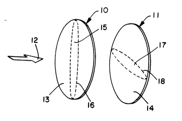
substantially coincide. This concept is illustrated by FIG. 1 which diagr~mm~ti-cally shows only the anode filter elements of two apparatus in series. FIG. 1
shows a first anode filter element 10 and a second anode filter element 11 in
5 series, with the direction of flow of a gaseous medium indicated by the arrow 12.
The first anode filter element 10 consists of a porous fibrous sheet material 13 and the second anode filter element 11 consists of a porous fibrous sheet material
14. The first anode filter element 10 has a portion 15, represented as the area
enclosed by dashed line 16, which remains substantially free of particulate matter.
10 Similarly, the second anode filter element 11 has a portion 17, represented as the
area enclosed by dashed line 18. which remains substantially free of particulatematter. Portions 15 and 17 do not substantially coincide.
The same result can be accomplished by coating the fibers of the porous
fibrous sheet material only in selected locations. The particulate matter will be
15 directed preferentially only to those portions of the anode filter element the fibers
of which have been coated with a metal. Referring again to FIG. 1, portions 15
and 17 also can represent areas of the anode filter elements 10 and 11,
respectively. in which the fibers have not been coated with a metal.
In a variation of the selective functionality described above. a similar result
20 is possible without changing the cathode configuration or operating conditions.
This embodiment is based on the configuration of the anode filter elements as
shown diagr~mm~tically in FIG. 2. FIG. 2 shows a first anode filter element 20
and a second anode filter element 21 in series, with the direction of flow of a
gaseous medium indicated by the arrow 22. The first anode filter element 20
25 consists of a porous fibrous sheet material 23 and the second anode filter element
21 consists of a porous fibrous sheet material 24. The first anode filter element
20 has apertures 25 and the second anode filter element 21 has apertures 26.
Apertures 25 and 26 do not substantially coincide.
- 14 -
214752~
The present invention is further described by the example which follows.
Such example, however, is not to be construed as limiting in any way either the
spirit or the scope of the present invention.
Example
Equipment and Procc.lule
With reference to FIG. 3, a model system 300 was constructed which
included the corona-assisted electrostatic filtration apparatus 302. The apparatus
302 was installed in a poly(methyl methacrylate) tube 304 having an inner
diameter of about 3 cm. and made in two sections, 306 and 308. The section
306 was roughly 90 cm long and the section 308 was about 15 cm in length.
`The apparatus 302 consisted of a cathode 310, an anode filter element 312, and
a high voltage, direct current power supply 314. The cathode 310 consisted of
a solid copper wire 316 which was connected to a power supply 314 and had a
diameter of about 1 mm. The wire 316 entered the section 306 of the tube 304
perpendicular to the wall 318 of the section 306. The portion of the wire 316
within the tube termin~ting in the cathode 310 had at the cross-sectional centerof the section 306 a 90 bend. directing the cathode 310 toward the center of the
anode filter element 312. The end of the cathode 310 was about 6 cm from the
anode filter element 312. The distance from the end of the cathode 310 to the
90 bend of the wire 316 was about 5 cm.
The anode filter element 312 consisted of a single layer of a spunbonded
polypropylene nonwoven web prepa~ed on pilot scale equipment essentially as
described in U.S. Patent No. 4,360,563. The web was thermally point-bonded
and had a basis weight of 1 ounce per square yard (about 24 grams per square
meter). The fibers of the nonwoven web were coated with copper metal.
The procedure employed to coat the fibers of the spunbonded nonwoven
web with copper was that of Esrom et al.. described earlier. and involved first
- 15 -
21~7~2q
cutting the web into 8 cm x 15 cm samples without touching them in order to
avoid depositing body oils on the fibers. A palladium(II) acetate solution was
prepared by dissolving the salt in chloroform at a concentration of 0.25 g per 30
ml of solvent. A sample of the nonwoven web was placed in a beaker of a size
5 such that the fabric was laying flat on the bottom of the beaker. The sample was
carefully covered with 100 ml of the palladium(II) acetate solution. The sample
was withdrawn from the solution carefully with tweezers and the solvent was
allowed to evaporate while turning the sample several times to keep the solutionas uniformly distributed on the web as possible. Each side of the sample was
exposed sequentially for five minutes in a vacuum chamber at 0.1 Torr to 172-
nm excimer radiation from a Xe~ excimer lamp assembly. The distance from
the lamps to the sample was about 2.5 cm. The power density of each lamp was
about 500 watts per square meter (about 1,000 watts per pair of lamps having
lengths of 30 cm).
The excimer lamp was configured substantially as described by Kogelschatz
and Eliasson et al., supra, and is shown diagrammatically in FIG. 4. With
reference to FIG. 4, the excimer lamp 400 consisted of three coaxial quartz
cylinders and two coaxial electrodes. The outer coaxial quartz cylinder 402 was
fused at the ends thereof to a centrai coaxial quartz cylinder 404 to form an
annular discharge space 406. An excimer-forming gas mixture was enclosed in
annular discharge space 406. An inner coaxial quartz cylinder 408 was placed
within the central cylinder 404. The inner coaxial electrode 410 consisted of a
wire wound around the inner cylinder 408. The outer coaxial electrode 412
consisted of a wire mesh having a plurality of openings 414. The inner coaxial
electrode 410 and outer coaxial electrode 412 were connected to a high voltage
generator 416. Electrical discharge was m~int~ined by applying an alternating
high voltage to the coaxial electrodes 410 and 412. The operating frequency was
40 kHz, the operating voltage 10 kV. Cooling water was passed through the
inner coaxial quartz cylinder 408, thereby maintaining the temperature at the
- 16 -
- 2147524
outer surface of the lamp at less than about 120CC. The resulting ultraviolet
radiation was emitted through openings 414 as shown by lines 418. The lamp
was used as an assemblv of four lamps 400 mounted side-by-side in a parallel
arrangement.
S The sample of nonwoven web then was placed in a clean beaker of the
same size used previously. An electroless copper bath (Cuposit CP-78, Shipley
GmbH, Stuttgart, Germany) at ambient temperature was applied to both sides of
the sample, following the manufacturer's instructions for the preparation of thebath. The total volume of bath employed was about 500 ml. The application
procedure required carefully turning the sample over several times with tweezers.
The total time of exposure of each sample to the electroless copper bath typically
was from about 30 seconds to about l minute. The sample then was removed
from the bath, rinsed thoroughly with water, and dried in a vacuum oven.
Returning to FIG. 3, circular portions of the copper-coated nonwoven web
samples were cut out, such that such portions had a diameter slightly larger than
the outer diameter of tube 304. A single circular portion became an anode filterelement 312 by simply placing the portion between sections 306 and 308 of the
tube 304 and clamping the two sections together (clamp not shown). A ground
wire 320 was attached to each newly installed anode filter element 312 by means
of an ~llig~tor clamp (not shown).
Air was supplied from a cylinder 322, passing through a control valve 324
into a calibrated particle feeder 326 (Wright Particle Feeder L. Adams Ltd.,
London, F.ngl~nrl) which was used to seed the entire gas flow with titanium
dioxide powder (Fisher Scientific Company, Pittsburgh, Pennsylvania) having
particle diameters of about one micrometer. Because the lowest feed rate of the
feeder 326 was too high, an Erlenmeyer flask 328 was used to reduce the powder
concentration entering the tube 304. The air flow rates employed, 20 liters per
minute and 30 liters per minute, were not sufficiently high to keep all of the
titanium dioxide suspended; thus. excess powder simply settled by gravity in the
2147 j2~
.
flask 328. Air containing the titanium dioxide particles exited the flask 328 and
entered the tube 304 at the end 330. The length of the section 306 of the tube
304 was selected to reduce the turbulence of the air as it entered the tube 304 and
to allow the air movement toward the apparatus 302 to approach l~min~r flow
5 conditions.
As the air approached the a~pa~al~ls 302, a pressure reading was taken by
means of a manometer 332. The air moved past the cathode 310 and through the
anode filter element 312. Another pressure reading was taken by the manometer
334 after the air had passed through the anode filter element 312. The air then
exited the tube 304 through the end 336 into a high efficiency filter 338 attached
to the section 308 by a clamp 340 to collect any titanium dioxide powder not
retained by the anode filter element 312.
The efficiency of the anode filter element 312 in capturing or retaining
titanium dioxide powder was determined by weighing each anode filter element
before installing it in the filtration system 300. The filter 338 also was weighed
before each experiment. The percent of powder captured was calculated as 100
times the quotient of weight gained by the anode filter element 312 divided by the
sum of the weight gained by the anode filter element 312 and the filter 338.
An air flow rate of 20 liters per minute gave a linear air velocity through
20 the anode filter element of 0.47 meter per second. The titanium dioxide powder
loading varied from 5-600 mg/m3, a range which is typical in domestic
applications.
Experiments first were done with the power off, i.e., without a corona
field, to determine a baseline. Experiments then were conducted with power on
25 at 8,400 volts, which was the highest voltage which gave minim~l sparkover. At
8,400 volts, the corona current varied from 13 to 42 milli~mps (mA). The
current varied slightly during each experiment but exhibited no specific trend.
The difference in current from experiment to experiment probably was due to
slightly different distances between the corona wire and the filter.
- 18 -
21~752~
Experimental Results
The results of a number of experiments at air flow rates of 20 and 30 liters
per minute are summarized in Tables 1 to 4. In the tables "Exp" represents the
experiment number; "Total Powder Concn." is the concentration of the titanium
S dioxide powder in the air being passed throu~h the system. in mg per cubic
meter; "AFE Weight" is the weight in mg of titanium dioxide retained or
captured by the anode filter element; "AFE Powder Concn." is the amount of
titanium dioxide powder retained or captured by the anode filter element,
expressed as a concentration in mg per cubic meter; "PD (Pa)" is the pressure
10drop or difference in pressure readinPs of the manometers 332 and 334, in
Pascals; and "Percent Calculated" is the amount of the powder retained by the
anode filter element, calculated as already described.
Table 1
S--mmqry of Individual Experiments with No Corona Field
and An Air Flow Rate of 20 Liters per Minute
Total AFE AFE
Powder Time Wei,~ht Powder Percent
Exp Concn. (Min.) (mg) Concn. PD (Pa) Captured
68.6 21 23.9 56.9 922 83.0
11 50.4 14 9.1 32.5 98 64.5
12 143.4 6 10.6 87.5 196 61.0
13 84.3 20 26.2 65.5 1118 77.7
14 58.9 32 29.7 46.4 1118 78.8
21.7 20 4.0 10.0 39 46.0
16 28.0 25 8.5 17.0 59 60.7
17- 22.8 20 6.1 15.3 ~9 67.0
- 19 -
2147524
Table 2
S~mm~ry of Individual Experiments with 8,400-Volt Corona Field
and An Air Flow Rate of 20 Liters per Minute
Total AFE AFE
Current Powder TimeWeight Powder Percent
fmA) Concn. (Min.) (m~) Concn. PD (Pa) Captured
14 87.5 4 5.0 62.5 39 71.4
2 42 38.6 18 10.9 30.3 39 78.4
3 30 175.1 6 15.4 128.3 196 73.3
4 29 93.3 12 15.9 66.3 98 71.0
5 42 45.4 25 29.6 39.2 59 86.3
6 20 582.6 4 41.9 523.8 373 89.9
7 15 7.5 20 1.9 4.8 10 63.3
8 17 80.0 8 8.7 54.4 10 68.0
9 17 13.3 20 3.7 9.3 10 69.8
Table 3
S-lmm~ry of Individual Experiments with No Corona Field
20and An Air Flow Rate of 30 Liters per Minutea
Total AFE AFE
Powder Time Weight Powder Percent
ExpConcn. (Min.) (m~) Concn. PD (Pa) Captured
39.0 20 15.7 26.2 275 67.1
21 69.2 8 10.1 42.1 177 60.8
22 243.2 2 8.1 135.0 118 55.5
26 61.7 6 6.6 36.6 98 59.4
- 20 -
~1~7~2~
aTwo experiments were not included because the nature of the titanium
dioxide powder appeared to differ from that of the other experiments.
Table 4
S S~mm~ry of Individual Ex~ nts with ~,400-Volt Corona Field
and An Air Flow Rate of 30 Liters per Minuteb
Total AFE AFE
Current PowderTime Weight Powder Percent
~ (mA) Concn. (Min.) (mg) Concn. PD (Pa) Captured
18 21 63.3 6 9.7 40.4 59 63.8
19 14 59.7 8 12. 1 40.3 1 18 67.6
13 68.3 8 6.7 37.2 78 54.5
bOne experiment which employed an insulated cathode wire was not included:
the insulation altered the characteristics of the corona field.
The functional selectlvity of the apparatus and method of the present
invention is shown in FIGS. 5-8. FIG. 5 is a color photograph of an anode filterelement employed in the example, prior tO use. FIG. 6 is a color photo_raph of
the anode filter element at the end of Experiment 13 (Table 1). FIGS. 7 and 8
are color photographs of the anode filter elements at the end of Experiments 2
and 3, respectively (Table 2). FIGS. 7 and 8 illustrate the phenomenon of
functional selectivity, in that particulate matter collected on most of the surface
of the element, except for a roughly oval vertical central portion. Such
phenomenon is the reason why Experiments 2 and 3 exhibited pressure drops of
39 and 196 Pascals, respectively, whereas Experiment 13 exhibited a pressure
drop of 1118 Pascals.
The data presented in Tables 1-4 involve three variables: (1) the presence
or absence of a corona field, (2) the concentration of titanium dioxide powder in
- 21 -
214752g
the air stream, and (3) the duration or time of each experiment. Thus. the
percent of powder captured by the anode is a function of those three variables.
Consequently, an analysis of the data is required in order to fully appreciate the
effect of the present invention on filtration efficiency.
S The filtration efficiency (FE) for each experiment included in Tables 1-
4, inclusive, was calculated by dividing the percent captured value by the amount
of titanium dioxide powder, in mg, retained by the anode filter element. The
results are summarized in Table 5.
Table S
Calculated Filtration Efflciencies
20 L/Min. Air Flow Rate 30 L/Min. Air Flow Rate
W/O Corona With Corona W/O Corona With Corona
Exp FE Exp FE Exp FE Exp FE
3.47 1 14.3 20 4.27 18 6.58
11 7.09 2 7.19 21 6.02 19 5.59
12 5.75 3 4.76 22 6.85 25 8.13
13 2.97 4 4.47 26 9.00 Ave. 6.77
14 2.75 5 4.40 Ave. 6.54
11.5 6 2.15
16 7.14 7 33.3
17 11.0 8 7.93
Ave. 6.46 9 18.9
Ave. 10.8
With an air flow rate of 20 liters per minute. the use of corona resulted in an
approximately 67 percent improvement, based on the avera~e filtration efficiency
- 22 -
214752~
.
values. At an air flow rate of 30 liters per minute the improvement in average
filtration efficiency was approximately 4 percent.
In accordance with standard practice in the filtration art. the amount of
powder captured by the anode filter element, in mg, was plotted versus the
percent of powder captured by the anode filter element~ first without a corona
field and then with a corona field, both with an air flow rate of 20 liters per
minute (data from Tables 1 and 2, respectively). In each case, the best fitting
curve was estim~te~l and drawn manually. The plots are shown in FIG. 9; the
plot without corona is a dashed line and the plot with corona is a solid line.
Similar plots were prepared for an air flow rate of 30 liters per minute and areshown in FIG. 10 (data from Tables 3 and 4. respectively).
The calculations shown in Table 5, together with FIGS. 9 and 10. clearly
show the improvement in filtration efficiency. It is evident that the use of a
corona field was more effective at the lower air flow rate. Because corona driftvelocities tend to be quite low, the higner air flow rate tended to negate the effect
of the corona field. It also is apparent that filtration efficiency improves with
increasing accumulations of particulate matter on the anode filter element.
A dramatic decrease in pressure drop resulting from the use of a corona
field in accordance with the present invention also is evident from Tables 1-4.
inclusive. At an air flow rate of 20 liters per minute, the average pressure drops
without and with corona are 449 Pa and 93 Pa, respectively~ a reduction of
almost 80 percent. At an air flow rate of 30 liters per minute. the average
pressure drops without and with corona are 167 Pa and 85 Pa, respectively, a
reduction of almost 50 perce,lt.
In order to better understand the relationship of pressure drop to anode
filter element loading, the pressure drop for each experiment was plotted versusthe actual amount of titanium dioxide powder captured by the anode filter
element, first without corona and then with corona, both at an air flow rate of 20
liters per minute (data from Tables 1 and 2, respectively). In each case~ the best
2147~2~
fitting curve was estim~te~ and drawn manuallv. The plots are shown in FIG.
11. As with FIGS. 9 and 10, the plot without corona is a dashed line and the
plot with corona is a solid line. Similar plots were prepaled for an air flow rate
of 30 liters per minute and are shown in FIG. 12 (data from Tables 3 and 4
5 respectively).
At an air flow rate of 20 liters per minute~ the differences in the effect of
filter element loading on pressure drop are remarkable. When a corona field was
not present, the pressure drop rose relatively slowly, perhaps even linearly, until
a loading of about 8 mg was reached. Pressure drop then increased rapidly with
10 increased loadings and appears to be approaching a maximum pressure drop at
an anode filter element loading of about 30 mg. With a corona field, however~
the pressure drop rose far more slowly with increasing anode filter element
loadings. Moreover, at an anode filter element loading over 40 mg, the pressure
drop with corona was roughly equivalent to a loading without corona of about 15
15 mg. When the air flow rate was increased to 30 liters per minute. the pressure
drop appeared to increase linearly with increased anode filter element loading,
both without and with corona. However, the pressure drop increased more
rapidly without corona than with it.
While the specification has been described in detail with respect to specific
20 embodiments thereof, it will be appreciated that those skilled in the art, upon
~tt~ining an understanding of the foregoing, may readily conceive of alterationsto, variations of, and equivalents to these embodiments. Accordingly, the scope
of the present invention should be ~sessed as that of the appended claims and
any equivalents thereto.
- 24 -