Note: Descriptions are shown in the official language in which they were submitted.
21~7~6~
-
DISPENSING PUMP
This invention relates to a dispensing pump
primarily but not exclusively for the nasal
administration of a liquid spray from a container in
the form of an ampule with an elastomeric seal closure.
It is known to provide pumps, typically fitted
with spray nozzles adapted for nasal or opthalmic use,
in which the pump is fitted to a container and the
container filled with a quantity of liquid to be
subsequently dispensed. In order to maintain the
integrity of the liquid during storage, it is
necessary to provide some means of sealing the
enclosed volume of liquid against the ingress of
contaminants including moisture and bacteria and also
against evaporative loss. For certain liquid
substances, prolonged contact with air cannot be
tolerated.
It is an object of the present invention to
provide a pump suitable for dispensing liquid from a
container wnich is sealed until immediately prior to
use of the pump and which allows the liquid to be
conveniently adminstered with minimal wastage. This
is a particular requirement where a small volume of
liquid drug having a high value is to be dispensed.
It is a further object of the present invention
to provide a pump which can be made ready for use
immediately after the seal of the container is first
opened.
According to the present invention there is
disclosed a pu~np for use in dispensing liquid from a
container defining a reservoir which is accessible via
a container mouth closed by a disruptable seal, the
pump comprising a body defining a chamber, a tubular
inlet portion defining an inlet channel communicating
21~7~G
with the cha-mber, an actuating stem defining a
dispensing channel through which liquid is dispensed
from the chamber in use, and a housing being connected
to the body and comprising holding means operable to
hold the container in use such that in a first
position of the container relative to the body the
inlet portion is external to the disruptable seal and
in a second position of the container relative to the
body the inle~ portion extends through the seal into
the reservoir ~hereby the inlet channel communicates
with the reservoir, characterised in that the inlet
portion projects into the reservoir in the second
position of the container relative to the body to an
extent sufficient to displace a volume of liquid
sufficient to fill the inlet channel and to occupy the
pump chamber.
Air may thereby be fully purged from the pump
chamber ready for use so that the pump may be regarded
as self priming.
A further advantage of such a pump is that the
container may remain sealed until immediately prior to
the first use of the pump at which time the seal is
penetrated by the inlet portion.
Preferably the housing defines a cylindrical
recess and the holding means comprises a tubular
holder slidably received in the recess.
Advantageously the holding means further
comprises co-operating catch formations of the holder
and the housing respectively, the catch formations
being operable to retain the holder in respective
first and second positions relative to the housing
corresponding to the first and second positions of the
container relative to the body and being releasable to
facilitate movement of the holder between the first
and second positions.
The container may thereby be packaged with the
21~7~6~
pump such that during storage the container remains
sealed and the container is held in its first position
relative to the body ready for first use of the pump.
Preferably the inlet portion comprises a tubular
extension of the body of the body and defines a
cylindrical surface which is sealingly engageable in
use by the seal during penetrating movement by the
inlet portion, the surface being co-operable with the
seal to maintain closure of the container mouth.
An advantage of this arrangement is that
maintaining an airtight closure at the mouth of the
container during penetration allows liquid to be
displaced by penetration of the inlet portion into the
container such that liquid is forced into the pump via
the inlet channel. The pump chamber, in its
configuration of minimum volume, may thereby be filled
with liquid and purged of air by the inflow of
liquid. Subsequent expansion of the pump chamber to
its maximum volume will then draw liquid into the
chamber to rully prime the pump ready for first
actuation.
- Conveniently the tubular extension comprises an
indentation in the cylindrical surface at a location
such that in the second position of the container
relative to the body the indentation defines a by-pass
channel in registration with the seal to facilitate
the ingress of air to the reservoir.
The by-pass channel thereby enables the pressure
within the container to be maintained at ambient
pressure when ~iquid is pumped from the container.
Advantageously the pump further comprises an
actuator connected to-the actuating stem and defining
a dispensing outlet and at least one gripping
formation facilitating manual displacement of the
actuator relatlve to the holding means whereby, in
use, the actuator and holding means are relatively
2147~66
displaceable to effect depression of the actuating
stem relative to the body thereby actuating the pump
and providing relative movement of the container and
the body between the first and second positions.
Preferably the pump comprises a first spring
means operable between the actuating stem and the body
whereby the actuating stem is normally biassed into an
extended position and is movable against spring bias
into an actuated position, the first spring means
providing a first spring force which is less than a
dislocation force required to dislocate the holding
means from the first position such that movement of
the actuator relative to the holding means effects
movement of the container from the first position into
the second position only after the stem is depressed
into the actuated position.
Such an arrangement ensures that the piston is
moved into a position in which the volume of the
chamber is minimised prior to introducing liquid into
the chamber, thereby assisting in the priming of the
pump by exhausting air from the chamber.
Preferably the pump comprises outlet valve means
operable to release fluid from the chamber into the
dispensing channel in response to the fluid pressure
exceeding a threshold value during displacement of the
actuating stem between the extended position and the
actuated position and valve opening means operable to
hold open the outlet valve means when the stem reaches
the actuated position.
Such outlet valve means has the advantage of
being self-opening when the stem is fully depressed
thereby ensuring that, when liquid is subsequently
forced into the chamber from the container, air is
able to escape from the chamber through the outlet
valve means and this ensures that the chamber is
filled with liquid.
2147~6~
Preferably the pump comprises a piston movable in
the chamber in response to movement of the actuating
stem to vary the chamber volume, the piston being
slidably mounted on the stem and biassed by action of
a second spring means into a seated position in which
the piston closes a passageway communicating between
the chamber and the dispensing channel, the piston
being displaceable relative to the stem against the
spring force o~ the second spring means in response to
excess fluid pressure within the chamber into an
unseated position in which the passageway is opened to
thereby constitute the outlet valve means.
Such an arrangement ensures that liquid is
dispensed via the actuator nozzle at a sufficient
pressure to ensure atomisation since the outlet valve
will only open when a sufficient fluid pressure is
present.
Preferably the body defines a stop formation
internally of the chamber at a location such that the
stop formation is engageable with the piston in the
actuated position of the stem so as to move the piston
into the unseated position and thereby constituting
the valve opening means.
The inlet portion may be formed integrally with
the body or alternatively may be formed separately
from the body and may then be constituted by a dip
tube coupled to the body.
Dispensing apparatus in accordance with the
present invention may comprise a pump as disclosed
above in combination with a container which preferably
is constituted by an ampule having an elastomeric seal.
Preferred embodiments of the present invention
will now be disclosed by way of example only and with
reference to tne accompanying drawings of which:-
Figure ~ is a sectioned elevation of a pump with
a container fitted to a housing of the pump in
2147~66
-- 6 --
readiness for use;
Figure 2 is a sectioned elevation of the pump of
Figure 1 following a first stage of movement in which
the actuator stem is moved into its fully actuated
position;
Figure 3 is a sectioned elevation of the pump of
preceding Figures showing penetration of the seal by
the inlet portion;
Figure 4 is a sectioned elevation of the pump of
preceding Figures showing the actuator fully depressed
to a position in which the inlet portion extends fully
into the container;
Figure 5 is a sectioned elevation of the pump of
preceding Figures showing the subsequent stage of the
actuator having relaxed to a rest position in which
the pump chamber is primed ready for use;
Figure 6 is a sectioned elevation of an
alternative pump having a dip tube;
Figure 7 is a sectioned elevation showing a
modification to the pump of preceding Figures in which
a dip tube is coupled externally onto the pump body;
and
Figure 8 is a sectioned elevation of an
alternative container for use with the pump of any of
the preceding Figures, the container comprising a duck
bill valve seal.
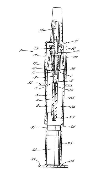
In Figure 1 a pump 1 comprises a body 2 defining
a cylindrical chamber 3 and having an inlet portion 4
with an elongate external cylindrical surface 5. The
inlet portion 4 defines an inlet channel 6
communicating with the chamber 3 via an inlet valve 7
comprising a spherical valve member 8 co-operating
with an annular valve seat 9, the inlet valve being
arranged to allow the flow of liquid into the chamber
and to close the inlet channel in response to excess
fluid pressure within the chamber.
2147366
_ 7 -
An actuat,ng stem 10 extends co-axially within
the chamber 3 and projects from the body 2 so as to be
externally accessible, an end portion 11 of the stem
being connected to an actuator 12.
The stem 10 defines a dispensing channel 13 for
the discharge ~f liquid from the chamber 3, the
dispensing channel communicating with an outlet duct
14 defined by the actuator. The actuator 12 further
defines a spray nozzle (not shown) communicating with
the outlet duc~ 14 and is shaped so as to be suitable
for nasal insertion.
An innermost end portion 15 of the stem 10 closes
the dispensing channel 13 and a radially extending
passageway 16 adjacent to the innermost end portion
provides communication with the chamber 3. An annular
piston 17 is slidably received externally on the stem
10 and normally overlays the passageway 16 so as to
constitute an outlet valve means 18.
The stem 10 is biassed into an extended position
by a first spring 19 and a second spring 20 acts
between an annular projection 21 of the stem and the
piston 17 so as to normally bias the piston towards
the innermost end portion 15.
A stop formation 22 in the form of a radially
inwardly projecting flange is formed in the body
adjacent to the inward limit of travel of the
innermost end portion 15 and is arranged such that,
immediately before the stem reaches its fully actuated
position, the piston 17 encounters the stop formation
22 thereby being arrested. Continued travel of the
stem into the fully actuated position exposes the
passageway 16 and thereby opens the outlet valve means
18 as shown in Figure 2.
A generally cylindrical housing 23 is connected
externally to ~he body 2 and extends co-axially with
the inlet portion 4 to define a cylindrical socket 24
21~7566
within which the inlet portion extends. A tubular
holder 25 is received in the socket 24 so as to be
telescopically movable relative to the housing 23
between a first position as shown in Figures 1 and 2
and a second position as shown in Figure 4 and 5.
A container 26 in the form of a glass ampule is
located within the holder 25 so as to be held in a
position in which a mouth 27 of the container is
presented to a pointed leading end 28 of the inlet
portion 4. The container 26 has an elastomeric seal
29 in the form of a disruptable diaphragm normally
closing the mouth 27. The container 26 defines a
reservoir 30 for a sterile liquid drug to be nasally
adminstered.
The seal 29 is supported by a metal ferrule 31
which has a central aperture slightly larger than the
external diamet:er of the cylindrical surface 5.
The actuator 12 is provided with gripping
formations ~2 projecting radially outwardly of the
pump 1, the formations being suitable for gripping by
two fingers of a user, the holder 25 having a handle
portion 33 adapted to be depressed by the user's thumb
when the fingers engage the gripping formations such
that a squeezing action conveniently impells the
actuator and the holder 25 towards one another.
During such actuating movement, the holder 25
initially remains stationary relative to the housing
23 by virtue of snap-fit catch formations 34, an
initial stage of movement thereby being provided in
which the actuating stem 10 is depressed relative to
the body 2. The volume of the chamber 3 is reduced
during this initial stage of movement by action of the
piston 17. Air within the chamber 3 is compressed and
released at the limit of travel of the actuating stem
when the outlet valve means 18 is opened by engagement
between the piston 17 and the stop formations 22.
21~7~66
. g
Continued movement of the actuator towards the
holder 25 disengages the snap-fit catch formations 34
so that the holder 25 and the body 2 move towards one
another. The leading end 28 of the inlet portion 4
then moves into contact with the seal 29 and is
progressively urged through the seal into the
reservoir 30. During the passage of the inlet portion
4 through the seal 29, the seal makes sealing contact
with the cylindrical surface 5 thereby resulting in
the liquid within the reservoir 30 becoming
pressurised since the available volume within the
reservoir 30 is progressively decreased by
displacement as the inlet portion 4 progressively
moves within it. Pressurised liquid enters the inlet
channel 6 and passes through the inlet valve 7 into
the chamber 3, in doing so displacing air from the
inlet channel 6 and the chamber and resulting in this
air being expelled through the dispensing channel 13.
Relative movement between the actuator 12 and the
holder 25 is arrested by engagement of further
snap-fit catch formations 35 which thereafter maintain
the container 26 in its second position relative to
the body 2.
The inlet portion 4 is recessed to provide an air
vent 36 which by-passes the seal 29 only when the
inlet portion is fully inserted into the container as
shown in Figures 4 and S. This air vent prevents the
creation of a vacuum within the container as liquid is
dispensed.
In this position the pump 1 is primed by the
presence of liquid within the chamber 3. The actuator
is then released and returns to its rest position by
action of the first spring 19 which moves the stem 10
into its extended position. During this travel the
piston 17 is returned to its normal rest position in
abuttment with the innermost end portion 15 of the
21~7~66
-- 10 --
,
stem in which the passageway 16 is closed. The volume
of the chamber 3 is increased during this travel and,
since the outlet valve means 18 is closed, liquid is
drawn through the inlet valve 7 from the reservoir 30
via the inlet channel 6.
The pump 1 is now fully primed and ready for
use. The actuator 12 is presented to the user's nasal
cavity and the user then applies manual pressure
between the gripping formations 32 and the handle
portion 33. By this action, the actuator 12 remains
in a fixed position and the body 2 is driven upwardly
so as to achieve relative movement of the stem 10
within the chamber 3. The volume of the chamber 3 is
reduced and, because liquid is substantially
incompressible, a rapid rise in fluid pressure within
the chamber is achieved thereby forcing open the
outlet valve means 18 by displacing the piston 17
against the spring force of the second spring 20.
On comple~ion of the actuating stroke, release of
the actuator 12 allows the stem and piston to return
to their rest positions under action of the first
spring 19 ther~by recharging the chamber with liquid
and the pump i6 again ready for use. Typically a
sufficient volume of liquid is provided within the
reservoir 30 for four successive actuating strokes to
deliver a spray of liquid.
The sequence of operation illustrated with
reference to Figures 1 to 5 is as follows. In Figure
1, the pump 1 and container 26 are in a storage
configuration in which the seal 29 remains intact and
the container is securely held in spaced apart
relationship relative to the inlet portion 4 of the
pump.
In Figure 2, an initial movement of the actuator
3~ 12 vents air from the pump chamber 3 and fully
depresses the stem 10 while at the same time engaging
21~7~
the piston 17 against the stop formation 22 so that
the outlet valve means 18 in held open.
In Figure 3, continued movement of the actuator
12 is shown intermediate the first and second
positions of the container 26 relative to the pump
body 2, the in;et portion 4 being shown penetrating
the elastomeric seal 29.
In Figure 4 the actuator 10 is fully depressed
such that the inlet portion 4 extends to its maximum
extent into the container 26 and has displaced liquid
through the inlet channel 6 into the pump chamber 3.
This inflow of liquid expels air through the outlet
valve means 18 so as to be vented via the dispensing
channel 13.
Figure 5 shows the position of the actuator 12
following relaxation of manual squeezing action
between the gripping formations 32 and the handle
portion 33, the actuator stem 10 having been returned
by spring action to its extended position and further
liquid having been drawn into the chamber 3 by
associated retraction of the piston 17 so that the
pump chamber is now fully primed with liquid.
Figure 5 therefore shows the pump 1 ready for
use. During subsequent use the container 26 remains
in its second position as shown in Figures 4 and 5.
Depression and release of the actuator 12 at each
actuating stroke of the pump 1 results in liquid being
displaced from the chamber 3 and released by operation
of the outlet valve means 18, the chamber be
replenished with liquid during the return stroke of
the actuator via the inlet valve 7.
An alternative pump is illustrated in Figure 6
where corresponding reference numerals are used for
corresponding elements where appropriate.
The pump of Figure 6 incorporates an inlet
portion 4 which is formed separately from the body 2
2147~66
- 12 -
and which is received as a push-fit within a
cylindrical recess 37 in the manner of a conventional
dip tube.
The arrangement of Figure 6 has the advantage
that a conventional displacement pump as shown may be
utilised by the addition of a suitable housing 23 and
actuator 12, the inlet portion or dip tube 4 being
selected to be substantially rigid and having a
pointed leading end to assist in penetration of the
seal 29.
An alternative arrangement is illustrated in
Figure 7 and will now be described using corresponding
reference numerals to those of preceding Figures where
appropriate for corresponding elements. In Figure 7,
a pump body 2 has an inlet 38 defined in an end
portion 39 which houses the inlet valve 7.
An inlet portion 4 is formed separately from the
body 2 and defines an inlet channel 6 extending
between a leading end 28 and a connector portion 40
which is received externally as a sliding fit onto the
end portion 39.
The inlet channel 6 thereby communicates with the
inlet 38 and conducts liquid from the reservoir 30 to
the pump chamber 3 in the same manner as described
above with reference to Figure 1.
The external diameter of the inlet portion 4 is
selected to be sufficient to displace the volume of
liquid from the reservoir required to effect self
priming of the pump by filling the inlet channel 6 and
pump chamber 3.
The embodiments of the pump disclosed above may
alternatively be used in conjunction with a container
of the type shown in Figure 8 and described using
corresponding reference numerals to those of preceding
Figures where appropriate for corresponding elements.
In Figure 8 a container 26 defines a reservoir 30
21~7~fi6
- 13 -
_
receiving liquid to be dispensed and having a mouth 41
sealed by means of a duck bill valve 42. the duck
bill valve 42 is arranged to project inwardly of the
mouth 41 such ~hat elastomeric lips 43 and 44 of the
valve are normally resiliently biassed together in a
sealed configuration. During insertion of the leading
end 28 of the inlet portion 4 in use, the lips 43 and
44 are pushed apart and retained in sliding sealing
relationship with the cylindrical surface 5.
The container 26 may also be provided with a foil
seal (not shown) overlaying the mouth 41 during
storage and which is removable immediately prior to
use.
The actuator 12 disclosed with reference to the
above embodiments may be modified for alternative uses
of the pump, such uses may for example include
opthalmic use.