Note: Claims are shown in the official language in which they were submitted.
7
THE EMBODIMENTS OF THE INVENTION IN WHICH AN EXCLUSIVE
PROPERTY OR PRIVILEGE IS CLAIMED ARE DEFINED AS FOLLOWS:
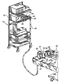
1. A patient monitoring system comprising a patient support platform, a
peripheral stand, monitoring displays on the peripheral stand, monitoring
probes
for attaching to a patient and a cable arrangement carrying monitoring data
between the patient support platform and the monitoring displays, the cable
arrangement comprising:
(a) a base unit positioned at the peripheral stand and having a series of
first connection points each connected to a respective one of the
monitoring displays in the stand, the base unit also having one or
more second connection points, each one of a series of input lines of
each first connection point being internally connected directly to one
of a series of input lines of the one or more second connection
points;
(b) a satellite unit adapted to be positioned on the patient support
platform, independent of the position of said monitoring probes on
the patient, and having a series of third connection points each
connected to a respective monitoring probe, the satellite unit also
having one or more fourth connection points, each one of a series of
input lines of each third connection point being internally connected
directly to one of a series of input lines of the one or more fourth
connection points; and
(c) a cable connecting the one or more second connection points in the
base unit directly to the one or more fourth connection points on the
satellite unit, the cable being readily detachable from the one or
more fourth connection points;
wherein all of the probes are connected to the satellite unit over the patient
support platform, all of the monitoring displays are connected to the base
unit at
the peripheral stand; and the platform and stand are connected solely by said
cable, the region between the patient support platform and the peripheral
stand
8
being thereby maintained in a less cluttered state than if each probe was
independently connectable to the respective display.
2. A cable arrangement as in claim 1, wherein there is only a single second
connection point and a single fourth connection point.
3. A system as in claim 1, wherein the patient support platform is a surgical
gurney.
4. A system as in claim 1, wherein the cable is detachable only from the
satellite unit.
5. A system as in claim 1, wherein the cable is detachable from both the base
unit and the satellite unit.
6. A system as in claim 1, wherein each of the input lines is adapted to carry
electrical signals.
7. A system as in claim 1, wherein the satellite unit is secured by fastening
means to the patient support gurney.
8. A system as in claim 1, wherein the satellite unit has a series of hook
members extending therefrom, each of the hook members being adapted to
support a probe cable extending between a probe and a respective one of the
third connection points on the satellite unit.
9. A system as in claim 7, wherein the satellite unit has a series of hook
members extending therefrom, each of the hook members being adapted to
support a probe cable extending between a probe and a respective one of the
third connection points on the satellite unit.
9
10. A system as in claim 1, wherein the probes comprise temperature, blood
pressure, oxygen level and heart electrical activity measurement devices.
11. A patient monitoring system comprising a patient support platform, a
peripheral stand, monitoring displays on the peripheral stand, monitoring
probes
for attachment to a patient, and a cable arrangement carrying monitoring data
between the patient support platform and the monitoring displays, the cable
arrangement comprising:
(a) a connection box adapted to be positioned on the patient support
platform, independent of the position of said monitoring probes on
the patient, the box having a series of first plug receptacles and one
or more second plug receptacles, each one of a series of input lines
for each first plug receptacle being directly internally connected to
one of a series of input lines of the one or more second plug
receptacles, each of the first plug receptacles receiving a plug from
a respective patient monitoring probe; and
(b) a cable having a plug on its one end connected detachably with the
one or more second plug receptacles of the connection box, the
other end of the cable terminating in a series of plugs each
connected to a respective monitoring display on the peripheral
stand;
wherein all of the probes are connected to the connection box, and the patient
support platform and the peripheral stand are connected solely by the cable,
the
region between the patient support platform and the peripheral stand being
thereby maintained in a less cluttered state than if each probe was
independently
connected to the respective display.
12. A system as in claim 11, wherein the patient support platform is a
surgical
gurney.
13. A system as in claim 11, wherein each of the input lines is adapted to
carry
10
electrical signals.
14. A system as in claim 11, wherein the connection box has a series of hook
members extending therefrom, each of the hook members being adapted to
support a probe cable extending between a probe and a respective one of the
first
plug receptacles.
15. A system as in claim 11, wherein the probes comprise temperature, blood
pressure, oxygen level and heart electrical activity measurement devices.
16. A patient monitoring probe connection system used in conjunction with a
patient support platform and remote monitoring equipment, said system
comprising multiple probes each applied at one end to a patient on the patient
support platform, a satellite connection bar adapted to be positioned on the
patient support platform, independent of the position of said probes on a
patient,
establishing connections between opposite ends of the probes and the remote
monitoring equipment, said satellite connection bar comprising first external
connectors for releasebly receiving opposite ends of said probes over the
platform, a second external connector, and internal connections within the bar
directly between said first external connectors on the one hand and said
second
external connector on the other hand; and
a consolidated connection cable having two ends with a connector at one
end complimentary to and releaseably connected to said second external
connector, and means at the other end connected to said remote monitoring
equipment.
17. A cable arrangement for use in carrying monitoring data from monitoring
probes on a patient support platform to monitoring displays on a nearby
peripheral stand, the cable arrangement comprising:
a. a cable having one or more data paths for transmitting data from the
11
monitoring probes to the monitoring displays;
b. a base unit to which the cable is connected and to which one or
more monitor displays can be connected, the base unit having a
data path through it connecting a data path in the cable to a
connected monitor;
c. a satellite unit adapted to be positioned on or near the patient
support platform, independent of the position of said monitoring
probes on the patient, and to which the cable is connected and to
which one or more probes attached to the patient can be connected,
the satellite unit having a data path through it connecting a data
path in the cable to a connected probe;
wherein all of the probes are connectable to the respective monitors by the
cable,
the region between the patient support platform and the peripheral stand being
thereby maintained in a less cluttered state than if each probe was
independently
connectable to the respective display
18. A cable arrangement as in claim 17 in which the cable can be
disconnected from the base unit or the satellite unit or both.
19. A cable arrangement as in claim 17 wherein the base unit is integral with
a monitoring display or an associated piece of equipment;
20. A cable arrangement as in claim 17 wherein the satellite unit is integral
with the cable.
21. A cable arrangement as in claim 17 wherein the base unit comprises a
cable extension of each data path ending in a plug for connecting to a
monitor.
22. A cable arrangement as in claim 17 wherein the satellite unit is integral
12
with the cable and wherein the base unit comprises a cable extension of each
data path ending in a plug for connecting to a monitor.
23. A patient monitoring cable arrangement comprising:
a. a cable body having one or more data paths for use in connecting
one or more selected patient probes with one or more selected
monitors;
b. a base unit at one end of said cable body and connectable to said
one or more selected monitors to connect said one or more data
paths to said one or more selected monitors; and;
c. a satellite unit at the other end of said cable body connectable to
said one or more selected patient probes to connect said one or
more data paths with said one or more selected patient probes, said
satellite unit being positionable independent of the position of any
selected patient probes on the patient.
24. The cable arrangement of claim 23 in which the satellite unit is integral
with the cable body.
25. The cable arrangement of claim 23 in which the base unit is integral with
the cable body.
26. The cable arrangement of claim 23 in which the base unit and the satellite
unit are integral with the cable body.
27. The cable arrangement of claim 23 in which the base unit comprises a
separate cable extension of each data path, the separate cable extension
having
a plug at the end adapted to connect to a monitor.
13
28. A patient monitoring system comprising a patient support platform, a
peripheral stand, monitoring displays on the peripheral stand, monitoring
probes
for attaching to a patient and a cable arrangement carrying monitoring data
between the patient support platform and the monitoring displays, the cable
arrangement comprising:
a. a cable having one or more data paths for transmitting data from the
monitoring probes to the monitoring displays;
b. a base unit to which the cable is connected and to which one or
more monitor displays can be connected, the base unit having a
data path through it connecting a data path in the cable to a
connected monitor;
c. a satellite unit adapted to be positioned on or near the patient
support platform, independent of the position of said monitoring
probes on the patient, and to which the cable is connected and to
which one or more probes attached to the patient can be connected,
the satellite unit having a data path through it connecting a data
path in the cable to a connected probe;
wherein all of the probes are connectable to the respective monitors by the
cable,
the region between the patient support platform and the peripheral stand being
thereby maintained in a less cluttered state than if each probe was
independently
connectable to the respective monitor display
29 A patient monitoring system as in claim 28 in which the cable can be
disconnected from one or both of the satellite unit and the base unit.
30. A patient monitoring system as in claim 28 wherein the base unit is
integral with a monitoring display.
14
31. A patient monitoring system as in claim 28 wherein the satellite unit is
integral with the cable.
32. A patient monitoring system as in claim 28 wherein the base unit
comprises a cable extension of each data path ending in a plug for connecting
to
a monitor.
33. A patient monitoring system as in claim 28 wherein the satellite unit is
integral with the cable and wherein the base unit comprises a cable extension
of
each data path ending in a plug for connecting to a monitor.
34. A cable arrangement for use in a patient monitoring system comprising a
patient support platform, a peripheral stand, monitoring displays on the
peripheral
stand, monitoring probes for attaching to a patient and a cable carrying
monitoring
data between the patient support platform and the monitoring displays, the
cable
arrangement comprising:
a. a cable body containing one or more data paths for use in
connecting a satellite unit and a base unit;
b. the base unit being connectable to one or more monitors and
providing a monitor data path from a data path in the cable to a
selected monitor;
c. the satellite unit being adapted to be positioned on or near said
patient support platform, and independent of the position of any of
said monitoring probes on said patient, and said satellite unit being
connectable to one or more probes attached to a patient and
providing a probe data path from a data path in the cable to a
selected probe.
15
35. The cable arrangement of claim 34 in which the satellite unit is integral
with the cable.
36. The cable arrangement of claim 34 in which the base unit is integral with
the cable.
37. The cable arrangement of claim 34 in which the base unit and the satellite
unit are integral with the cable.
38. The cable arrangement of claim 34 in which the base unit comprises a
cable extension of each data path, the cable extension having a plug at the
end
adapted to connect to a monitor.
39. The cable arrangementof claim 34 in which the satellite unit is integral
with the cable and wherein the base unit comprises a cable extension of each
data path-ending in a plug for connecting to a monitor.
40. A patient monitoring probe connection system used in conjunction with a
patient support platform and remote monitoring equipment, said system
comprising multiple probes each attached at one end to a patient on the
patient
support platform, a satellite unit adapted to be positioned on the platform,
independent of the position of said probes on the patient, said satellite unit
establishing connections between opposite ends of the probes and the remote
monitoring equipment, said satellite unit comprising first external connectors
for
releasably receiving opposite ends of said probes over the platform, a second
external connector, and internal connections within the bar directed between
said
first external connectors on the one hand and said second external connector
on
the other hand;
a cable having one or more data paths for transmitting data, the cable
also having two ends, one end being connected to said second external
connector so that data from a probe can be transmitted from the probe through
16
the satellite unit to a data path in the cable, and connection means at the
other
end of the cable connected to said remote monitoring equipment, to allow data
to
be transmitted through the cable to the remote monitoring equipment.
41. A patient monitoring probe connection system as claimed in claim 40 in
which the cable is detachably connected to the second external connector.
42. A patient monitoring probe connection system as claimed in claim 40 in
which the cable is permanently connected to the second external connector so
that the satellite unit is integral with the cable.
43. A monitoring cable arrangement for use in carrying monitoring data
between a patient support platform and a peripheral stand supporting
monitoring
displays, the cable arrangement comprising:
(a) a base unit adapted to be positioned on the peripheral stand and having a
series of first connection points each connectable to a respective one of the
monitoring displays on the stand, the base unit also having one or more second
connection points, each one of a series of input lines of each first
connection point
being internally connected to one of a series of input lines of the one or
more
second connection points;
(b) a satellite unit adapted to be positioned on the patient support platform,
and having a series of third connection points each connectable to a
respective
monitoring probe, the satellite unit also having one or more fourth connection
points, each one of a series of input lines of each third connection point
being
internally connected to one of a series of input lines of the one or more
fourth
connection points, said satellite unit being positionable independent of the
position of said monitoring probes on the patient, and,
(c) a detachable cable adapted to connect the one or more second connection
17
points on the base unit to the one or more fourth connection points on the
satellite
unit; wherein all of the probes are connectable to the respective displays by
the
cable, the region between the patient support platform and the peripheral
stand
being thereby maintained in a less cluttered state than if each probe was
independently connectable to the respective display.
44. A cable arrangement as in claim 43, wherein there is only a single second
connection point and a single fourth connection point.
45. A cable arrangement as in claim 43, wherein the patient support platform
is a surgical gurney.
46. A cable arrangement as in claim 43, wherein the cable is detachable only
from the satellite unit.
47. A cable arrangement as in claim 43, wherein the cable is detachable from
both the base unit and the satellite unit.
48. A cable arrangement as in claim 43, wherein each of the input lines is
adapted to carry electrical signals.
49. A cable arrangement as in claim 43, wherein the satellite unit is secured
by fastening means to the patient support gurney.
50. A cable arrangement as in claim 43, wherein the satellite unit has a
series of hook members extending therefrom, each of the hook members being
adapted to support a probe cable extending between a probe and a respective
one of the third connection points on the satellite unit.
51 A cable arrangement as in claim 43, wherein the probes comprise
temperature, blood pressure, oxygen level and heart electrical activity
18
measurement devices.
52. A monitoring cable arrangement for use in carrying monitoring data
between a patient support platform and a peripheral stand on which displays
are
mounted, the arrangement comprising:
(a) a connection box securable by fastening means to the patient support
platform, the box having a series of first plug receptacles and one or more
second
plug receptacles, each one of a series of input lines of each first plug
receptacle
being internally connected to one of a series of input lines of the one or
more
second plug receptacles, each of the first plug receptacles being adapted to
receive a plug from a respective patient monitoring probe, said connection box
being positionable independent of the position of said monitoring probes on
the
patient, and,
(b) a detachable cable having a plug on its one end adapted to connect with
the one or more second plug receptacles of the connection box, the other end
of
the cable terminating in a series of plugs each connectable to a respective
monitoring display on the peripheral stand; wherein all of the probes are
connectable to the respective displays by the cable, the region between the
patient support platform and the peripheral stand being thereby maintained in
a
less cluttered state than if each probe was independently connectable to the
respective display.
53. A cable arrangement as in claim 52, wherein the patient support platform
is a surgical gurney.
54. A cable arrangement as in claim 52, wherein each of the input lines is
adapted to carry electrical signals.
55. A cable arrangement as in claim 52, wherein the connection box has a
series of hook members extending therefrom, each of the hook members being
adapted to support a probe cable extending between a probe and a respective
19
one of the first plug receptacles.
56. A cable arrangement as in claim 52, wherein the probes comprise
temperature, blood pressure, oxygen level and heart electrical activity
measurement devices.
57. A cable arrangement for use in carrying monitoring data from one or more
monitoring probes on a patient support platform to one or more monitoring
displays on a nearby peripheral stand, the cable arrangement comprising:
a. a cable having one or more data paths for transmitting data from the
one or more monitoring probes to the one or more monitoring
displays;
b. a satellite unit at one end of the cable, the satellite unit being
connectable to one or more probes attached to a patient on the
patient support platform, said satellite unit being adapted to be
positionable on said patient support platform independent of the
position of any monitoring probe on the patient;
c. the satellite unit having a data through path connecting at least one
of said data paths in the cable to a connected probe and the satellite
unit being positionable on or near the patient support platform; and
d. a means, at the other end of the cable, for connecting each data
path to a monitoring display;
wherein all of the probes are connectable to the respective monitors by the
cable,
the region between the patient support platform and the peripheral stand being
thereby maintained in a less cluttered state than if each probe was
independently
connectable to the respective display.
20
58. The cable arrangement of claim 57 in which the satellite unit is integral
with the cable.
59. The cable arrangement of claim 57 in which the satellite unit is
permanently attached to the cable.
60. The cable arrangement of claim 57 in which the satellite unit is
detachable
from the cable.
61. The cable arrangement of claim 57 in which the means for connecting
each data path to a monitoring display is a cable extension of each data path
adapted to connect to a monitoring display.
62. A cable arrangement for use in a patient monitoring system comprising a
patient support platform, a peripheral stand, one or more monitoring displays
on
the peripheral stand and one or more monitoring probes for attaching to a
patient,
the cable arrangement comprising:
a. an elongate flexible cable body having one or more data paths for
transmitting data from the one or more monitoring probes to the one
or more monitoring displays;
b. a satellite unit on one end of the cable body and to which one or
more probes attached to a patient on the patient support platform
can be connected, the satellite unit having a data path through it
connecting a data path in the cable to a connected probe, the
satellite unit being adapted to be positioned on or near the patient
support platform independent of the position of said probes attached
to the patient.
63. The cable arrangement of claim 62 in which the satellite unit is integral
21
with the cable body.
64. The cable arrangement of claim 62 in which the satellite unit is
permanently attached to the cable body.
65. The cable arrangement of claim 62 in which the satellite unit is
detachable from the cable body.
66. The cable arrangement of claim 62 having means at the cable body end
distant from the satellite unit for connecting each data path to a monitoring
display.
67. The cable of claim 66 in which the means at the cable body end distant
from the satellite unit for connecting each data path to a monitoring display
is a
cable extension of each data path adapted to connect to a monitoring display.
68. The cable arrangement of claims 17, 18 or 19 in which there are two or
more data paths.
69. The patient monitoring cable arrangement of claims 23, 24 or 25 in which
there are two or more data paths.
70. The cable arrangement of claim 62, 63 or 64 in which there are two or
more data paths.