Note: Descriptions are shown in the official language in which they were submitted.
; `'.: WO 95/062122 1 4 7 7 ~ 9 ~CT/US93tO828g
FACE SEAL W:l:TH DOUBI.E
GROOVE ARRANG~ENT
,
FIELD OF THE INVENTION ..
This invention relates to sealing dèvices for -~
rotating shafts, wherein a sealed fluid is employed to .
generate hydrostatic-hydrodynamic or aerostatic-
aerodynami.c forces bètween opposed interacting face~
type sealing elements, one stationary and the other -
rotating. These forces provide far slight separation
and non-c~ntacting operation of the sealing elements, :~
thereby minimizing face wear and friction power losses
10 ~ while maintaining low fluid leakaye.
BACKGROUND OF THE INVENTION
: Rotary fluid :film face seals, also called gap or
non-contacting face ~eals, are usually appIied to high~
speed andlor high-pressure rotating:equipment wherein ~ ;
the use of ~rdinary~mechanical face seals with ~ace j .
' contact woul~ result in excessive heat generation and
wear. Non-contacting operation a~oids this undesirable ~ ~
face c~ntact at times when the~ shaft~is~rotating above a ~`` .
certain minimum speed, which is cal:led a li~t off spe
There are various ways of accompIishing~the above ?.,
: non-contacting operati~n~ One Qf the more c~mmonly usad ~ ~'
ways inc~udes the formation of a shallow spiral ~roove ~ .
pattern in one of the: ealing faces. The sealing face
. .~
W0~/06212 PCl~S93/082g~
2~477~ - 2 -
opposite the grooved face is relatively flat and smooth.
The face area where these two sealing faces defin~ a
sealing clearance is called the sealing interface.
The abover-mentioned spiral groove pattern on one of . ~
the sealing faces normally extends inward from the outer ~`-
circumference and ends at a partisular face dia~eter
called the groove diameter, which is larger then the
inner diameter of the seal interface. The non-grooved ,
area between the groove diameter and the inner interface
diameter serves as a restriction to fluid outflow.
Fluid deli~ered by the spiral pa~tern must pass through `-
this restriction and it can do so only if the sealing
faces separate. The way this works is through pressure
build-up. Should the faces remain in contact/ fluid
will be compressed just ahead of the restriction, thus
building up pressure. The pressure causes separation ';
force which eventually becomes larger than the forces
that hold the faces together. In that moment the
sealing faces separate and allow the fiuid to escape.
During operation of the,sea}, an equilibrium establishes
itself between fluid inflow through spiral pumping and
fluid outflow through face sepa-ation. Face separation
is therefore pre~ent as long as the seal is operating,
which means as long as one face i5 rotating in relation
to the opposite face. ~-
However, spiral pumping is not the only f actor that
determines the amount of the separation ~etween the
~ealin~ faces~ Just as the spirals are able to dri~
the fluid into the non-groove portion of the sealing
; 30 'inter~ace pas~ the groove diameter, so can the pressure
diff~rential. If enough of a pressure difference exists
betwean the groo~ed end of the interface and the non-
grooved end, fluid will also be forced into the non- ,
grooved portion of the interface, thereby separating the
faces and ~orming the clearance.
Both ways in which clearan e can be formed between
the sealing faces, one with speed of rotation~ the other
f - wo 95/OG212 2 1 4 7 7 3 9 PCT~593/08289
with pressure differential, are distinct and separate,
even though the effects of both combine on the operating
seal. If there is no pressure di~ference and the seal
~ace separation occurs strictly due to face rotation,
forces due to fluid flow are known as hydrodynamic
forces if the fluid sealed is a liquid, and a~rodynamic '
~orces if the fluid sealed is a gas.
On the other hand, if there is no mutual rotation
between the two sealing faces and face separation is
strictly the consequence of pressure differential
between both ends~of the sealing interface, forces due
to fluid flow are called hydrostatic forces if the fluid
sealed is a liquid, and aerostatics forces if the fluid
sealed is a gas. In the following, the terms
hydrostatic a~d hydrodynamic are used for both liquid
and gas effects since these latter terms are more
c~nventionally used when describing both liquid and gas
seals.
A typical spiral qroove seal needs to provide
acceptable performance in terms of leakag~ and the
absence of ~ace contact during all regimes of seal
op~ration. It must do so not only at top speed and
p~ssure, but also at standstill, at start-up,
acceleration, at periods of equipment warm-up or at
shutdown. At normal operating conditions, pressure and
speed vary constantly, which results in continuous
adjustments to the running clearance. These adjustments ~-
are automatic; one of the key properties of spiral :~
gro~ve seals is their self-adjustment capability. On
change in speed or pressure, the face clearance adjusts
automatically to a new set of conditions. Hydrostatic
and hydrodynamic forces c~use this adjustm~nt.
The operating envelope:of speeds and pressures i~
usually very wide and a seal design of necessity must be
a compromise. For its psrformance to be acceptable at
: near-zero speed or pressure, it is less than optimum at
~ operating speed and pressure. ~This is simply due to the ~`
WO~5106212 pcT~ss3lo8289~
2 ~ 3 9
- 4 -
fact that, both in terms of pressure and speed, the seal
has to be brought up to operating conditions from zero ~ `
speed and ~ero pressure differential.
Especially critical to seal operation is the start- .
up. If the seal is applied to a centrifugal gas
compressor, the full suction pressure diff2rential is
often imposed onto the seal before the shaft starts
turning. This presents a danger in that the sealing
faces will lock together with friction~ Face lock
results when the hydrostatic force is insufficient-to
counter pressure forces that maintain the seal faces in
contact. Face lock can lead to seal destruction, in
which excessive break-away friction between c~ntacting
seal faces can cause heavy wear or breakage of internal
seal components.
First t~1en, spiral grooYes must be able to separate
the sealing faces hydrodynamically ~or full speed non-
contacting operation. This normally requires fairly
short and relatively deep spiral grooves. Second, the
spiral groo~es must be able to unload the sealing faces
hydrostatically for start/stops to prevent face lock.
For this, the grooves have to be extended in length.
The extended grooves in turn cause more separation and
leakage during full speed operation. The full speed
leakage o~ a typical 3.75 inch shaft seal with short and
relatively deep spirals may be about .9 SCFM (i.e.
Standard Cubic Feet per Minute) at l,000 psig and lOrO00
rpm. However, full speed leakage for such a seal with
extended grooves may reach 2.4 SCFM un~er the same
~30 `c~nditions, almost triple the previous vaiue. The
constant burden of larger-than-necessary leakage
represent significant operating costs and is highly . D~""~
undesirable.
Spiral groove design prac~ice goes back to US Patent
No. 3,lOg,658 wherein two opposing spiral grooves pump
oil against each other to develop a liquid baxrier
capable of sealing a gas. Such an arrangement is
~ WO~5/06212 21 4 7 7 3 9 PCT1593/08289
- 5 -
limited in pressure as well as speed capability, as is
inherent in the use of liquid forces to seal gas.
Another known arrangement is shown in US Patent
No. 3,499,653. This interface design with partial
spiral grooves relies heavily on hydrostatic effects.
The interface gap is designed with a tapered shape which
is narrower at the non-grooved end and wider at the
spiral grooYes. The effect of the spiral grooves and
therefore the hydrodynamic forces are suppressed since
spiral groove pumping becomes less effecti~e across ~he
wider gaps. This likewise affects the stability of the
seal and limits its top pressure and speed capability.
A further known arrangement is shown by US Patent
~o. 4,212,475. Here the spiral groove itself attempts
to act both as a hydrostatic as well as a hydrodynami~
pattern and is used to eliminate ths need for the
tap~red shape o~ the gap so that a considerable degree
of spiral groove hydrodynamic force can be applied to
impart a self-aligning property to the sealing ~;~
interface. The self-aligning property forces the
sealing interface back towards a parallel po~ition,
regardless of whether deviations from parallel position
dur~ng seal operation occur in radial or tangential
directions. This resulted in improvement stability and ;~
increased performance limits in terms o~ pressure and
speed~
While the known fluid seals as briefly summarized
above have attempted to provide both hydrodynamic~and , i:
hydrostatic sealing properties, nevertheless the known
3iO seals have;bjeen deficient with respect to their ability
to optimize the combination of these hydrostatic and
hydrodynamic properties so as to provide desirable
hydrostatic properties which facilitate starting and
stopping of seals while effectively minimizing or
a~oiding direct face contact and minimizing face loading
between the seals so that the assembly can be start2d up -~'
with minimal friction to avoid severe frictional power
~,
',~
W0~5/Ofi~l~ PCT/US~3/08289 ~ ~ ~
~ 39 - 6 - l`
!
re~uirements and direct frictional wear between the
faces, and at the same time provide desirable
h~drodynamic properties between the relatively-rotatable
seal faces under a wide range of operating co~ditions~ ;
particularly those involving high speed and high 1-~
pressure.
Accordingly, it is an object of this invention to
provide an improved fluid seal of the type employing a
grooved pattern on one of the opposed seal faces, which
improved seal provides a more optimi~ed combination of
hydrodynamic and hydrostatic sealing characteristics SQ ..
as to permit improved seal performance under a
significantly greater range of operating conditions,
including operating conditions ranging from start up to
conditions involving high speed and high pressure. :
In the improved seal arrangement Qf the present
invention, the groove pattern (which is typically
defined on only one of the seal ~aces) includes first
and ~econd groove arrangements which co~municate with
one another, one being significantly deeper than the .;
other, whereby the deeper arrangement is particulaxly
effective for providing the desired hydrodyna~ic
characteristics, whereas the shallower groove
arrangement is more effective for providing the desired ~:
hydrostatic charazteristics. At the same time, these
arrangements are positloned such that the shallower .
arr~ngement is interposed generall~ between the deeper
groove arrangement and a non-grooYed annular land or dam
which effectively separates the groove pattern from the
! 30 lo~ pressure side of the seal, whereby desira~le
hydrostatic and hydrodynamic seal properties can both be ~ ~-
obtained but at the sam~ time leakage of sealing fluid
(for example, a gas~ across the dam to the low pres~ure
side is minimized so as to impro~e the performance
efficiency of the ~eal.
In addition, this optimization o~ the seal
propertîes and performance characteristics is further
21477~9
WO9~/06212 PCT~JS~3/08289
improved by optimizing the groove pattern or
configuration relative to the surrounding lands defined ¦ :
on the seal face so that the fluid film which is created
between the opposed seal faces provides a more uniform `
pressure distribution and sealing characteristics while
minimizing distortion of the seal faoe, ~hich in turn
assists in optimizing`the seal performance with minimum
width of gap between the opposed seal faces while still ~:
avoiding or minimizing direct contact and frictional ` ;
wear between the opposed seal faces. ;.
In the improved seal of this invention,~ as briefly :~
discussed above, the groove pattern includes the deep ;~`
groove arrangement which i5 defined:by:a circumfer- .
entially arranged series of grooves which angle circum~
ferentially and radially inwardly from the surroundin;g :
hlgh-pressure side of the seal, which angled~grooves may
be o~ spiral, circular or straight configuration. These
angled grooves are relatively deep and project only ..
partway across the seal:face. The angled deep grooves,
at their radially inner:ends, communicate with the ii
shallow groove arrangemen~ which is positioned radially
inwardly of the deeper groove arrangement,:but which is
separate~ from the low pressure side of the seal by:the
intermediate non-grooved annular land;or dam.~ This ~
:shallow groove~arrangement has a depth which is a small` :;.
fraotion of the deeper grooYe arrangement and is
~ e~f~ctive for: creati~g:a hydrostatic force:between the
:: :opposed sealing~faces substantially in the central : : :~
region thereof as defined between the ra~ially outer and ~ :;
;l3 . inner~boundarieslof the seal interface~ a! preferred ~! ' `'.. ~`-
embodiment, all grooves associated with the groove
pattern are form~d: ;such ~hat the sides of a~jacent~
~:~ grooves ex~end generally in parallelism~with one another
so that the intermediate land area:between~adjacent
grooves~maintains a su~stantially~constant width, even
adjacent thé radially;~:~inner ends~cf~the~grooves, to :
~àximize squeeze film effects~;~in the~;fluid whi h f1Ows
W095/06212 PC~S~3/0828~
2~ 39 - 8 - 1
- over these lands and thus enhance the thrust bearing
support these lands provide for avoidance of seal face
contact at or near the full speed rotation. ¦ ;
The improved seal arrangement, as aforesaid, also . ,
preferably forms the shallow groove arrange~ent by a
circumfere.ntially-spaced s2ries cf shall~w groove~ which
are contiguous with and project radially inwardly from
the inner ends of the angled deep grooves, which shallow
grooves terminate at the dam. These shallow grooves
pro~ide improved hydrostati~ seal characteristics in the
central seal face region, and angle radially inwardly at
a smaller angle (which angle is zero in a preferred
~mbodiment) re~ative to the radial direction than do the
deep grooves so as to increase the land area between the
adjacent shallow grooves, particularly adjacent the
radially inner ends of the shallow grooves, to provide a
~etter fluid sgueeze film effect between the opposed
seal faces during high speed rotation. -~
Further improvement to the hydrostatically effective
relatively shallow inner groove pattern is aimed at
reduction and elimination o~ any seal face distortions
that might occur as a result of circum~erential non- ;
uniformity of hydrostatic pressure fields as these form
above groove and land regions of the shallow groove
patt~rn at conditions at or near to the zero speed of
rotation. This improvement is a narrow and shallow
circumferential groove interconnecting inner ends of the
shallow inner gxoove pattern. Such a shallow
circumferential groove acts to equali2e pressure field ' -
nonl-uniformities circumferentially, as a result
suppressing any ~ace distortions and producing a uniform
face separation with no or only minimal face-to face ~;-
contact e~en at extremely low ma~itudes of separation
between the f~ces.
Other objects and purposes of the invention will be
apparent to persons familiar with seals of this general
:
'" '',
`
,~ W095/062l2 21 4 7 7 3 9 PCT~S93/08289
_ g _ i .
txpe upon reading the following specific~tion and
inspecting the accompanying drawings. i~
BRIEF DESCRIPTION OF THE DRAWINGS 1~
Figure 1 is a f~agmentary central sectional view
illustrating a generally conventional fluid face seal
arrangement, such as a grooved face ~e~l, associated
with a rotating shaft.
Figure 2 is a view taken generally along line 2-2 in
Figure 1 and illustrating the groove pattern associated
with a face of the rotating seal ring according to an
e~odiment of this invention.
Figure 3 is a fragmentary enlargement of a part of
Figure 2 so as to illustrate the groove~pattern in ~-
greater detail.
Figure 4 i5 a fragmentary sectional vi~w taken
~ubstantially along line 4~4 in Figure 3.
Figures 5 and 6 are views which correspond r ,',
respectively to Figures 3 and 4 but illustrate a
variation thereof. i~
~0 Figure 7 is a view similar to Figure 2 but showing a
further variation of the inner groove pattern.
Figure 8 is a ~iew similar to Figure 2 but showing
still a further and prsferred variation of the inner
groove pattern.
Figure 9 is a fragmentary enlargement of a part of
Figure 8 so as to illustrate the groove pattern in
greatex detail. ~-;
Figure lO is a fragmentary sectional view taken ~-
substantially along line lO-lO in Figure 9. ~ ;;
~;30 l ! ~igure~ 11 and 12 are views which correspond j ! j
respectively to Figures 9 and lO but illustrate a
variation thereof.
; Cert~in terminoIogy will be used in the following ~`
description for convènienca in reference onlyj and will
~ ~not be limiting. For exampla, the words~'lupwardly", j ~
; ~ "downwardly", "rightwardly"~and "leftwardly" will refer
''.. .'
'
:~ ~ '.;i'
W~g~/062l2 PCT~593/08289 ~` ~
~4,~39 -lo- ~`:
to direction~ in the drawings to which reference is
made. The words "inwardly" and "outwardly" will re~er
to directions toward and away from, respectively, the
geometric center of the assembly and designated parts
thereof. Said terminolo~y will include the words ~~ -
specifically mentianed, derivatives ~hereof, and words
of similar import.
DETAILED DESCRIPTION
Referring to Figure 1, therè is shown a typical
grooved face seal assembly 10 and its environment. This
environmenl comprisas a housing ll and a rotatable shaft
12 extending through said housing. The seial as~embly lO
is applied to seal a fluid (such as a pressurized ga~)
within the annular s~ace 13 and to restrict its escape
into the environment at 14. Basic components of the
seal assembly incl~des an annular, axially movable but
non-rotatable sealing ring 16 having a radially
extending flat face 17 in opposed sealing relationship
with a radially extending ~lat face 18 of an annular ~`
rotatable sealing ring 19 which is non-rotatably mounted
on the shaft 12. ~ing 1~ normally rotates in the
direction of the arrow ~Figure 2). The sealing ring 16
is located wi~hin cavity 21 of housing 11 and held
sub-qtantially concentric to rotatable sealing ring 19.
Between housing 11 and the sealing ring 16 is a
conventional anti rotation de~ice ~not shown) for ;
preventing rotation of ring 1~, as well a9 a plurality
of springs 22 spaced equidistantly around the cavity 21. ! `~
Springs 22 urge the sealing ring 16 toward engagement
with the sPalin~ ring 19~ An 0-rin~ 23 seals tha space
between the sealing ring 16 and the housing 11. The -
sealing ring 23 is retain~id in the axial position by a ~-
sleeve 24 which is c~ncentric with and locked on the
shaft 12, such as by locknut 25 threaded on shaft 12 as
shown. 0-ring seal 26 precludis leakage between the ~ ;
sealing ring lg and the sha~t 12.
~ woss/o62l2 21 4 7 7 3 9 PCT~593l08289 ¦ ~
The radially extending face 18 of the sealing ring
19 and radiall~ extending ~ace 17 of sealing ring 16 are
in sealing relationship~ and define an annular contact
area 27 therebetween, this being the seal interface.
This seal interface 27 is defined by a surrounding outer ~`
diameter 28 of ring 19 and an inner di^..me~er 29 of ring
16, these being the diameters exposed to the high and -
low pressure fluid respectively in the illustrated ~:
embodiment. In opèration, a very narrow clearance is '
maintained between the seal faces 17-18, due ~o a fluid ;.
~ilm as generated by a groove pattern (as described --
below) formed in the sealing face 18 of the sealing ring `~
19. Alternately, the groove pattern San be formed in
the sealing fae 17 of the sealing ring 16 and stiIl be
ef~ective. Said narrow clearance is maintained by the
~luid between the seal faces which prevents generation
of friction heat and wear, but the narrow clearance
limits out~low of the sealed fluid from the space 13 j`
into the region 14.
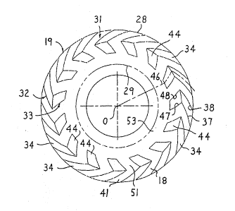
Referring now to Figure 2, there is illustrated the -^~
sealing face 18 of the sealing ring 19, which face has a
groove arrangement 31 ~ormed therein. This groove
arrangement 31 includes a first groove pattern 3~ which
is positioned primarily on the radially outer portion of
the ~ace 18. This groove pattern 32 normally provides
both hydrodynamic and hydrostatic ~orce in the seal~
interface 27, although it is the pr.mary source for `
generatin~ hydrodynamic force and hence will herein
often be referred to as the hydrodynamic region. The ~ ~
1 30 groove arrangement 31 also includes,a second groove i ~ i } ,i.. `
patt~r~ 33 whis_h is disposed generally radially inwardly
of the groo~e pattern 32 and is positioned genierally
within the center radia} re~ion of ~he face 18, that is ;i' ;~
the region which is spaced radial~y from both of the ~- ;
interface diameters 28 an~ 290 This latter groove
pattern or region 33 functions primarily to provide a
hydrostatic force betwesen the opposed seal faces 17-18
,,
.
,. .
WO9~/06212 PCT~$9310828g ,~
21~39 - 12 - ' ~
at conditions of near zero rotational speeds. The
groove patterns 32 and 33 may be formed in the face 18
using conventional fabrications techniques~ ¦
Considering first the hydrodynamic groove pattern
32, it is de~ined by a plurality o~ angled grooves 34
which are formed in the face 18 in substantially
uniformly angularly spaced relationship therearound.
These grooves 34 are all angled such that they open
radially inwardly from the outer diameter 28 in such
~ashion that the grooves simultaneously project
circumferentially and radially inwardly, and have an
angl~.d relationship with respect to both the
circumferential and radial directions of the seal face.
The angled groove 3~, as reprasented by the centerline
36 ~hereof where the groove intersects the outer
diameter 28, normally opens inwardly of the outer
diameter 28 at an acute angle relative to a tangent to
the outer diameter, which acute angle may be in the
neighborhood of 15 degrees.
Each angled groove 34 is defined by a pair of side
or edge walls 37 and 38. The inner ends of grooves 34 -
terminate generally at shoulders or abutments 39 which
are generall~ rather abrupt and are defined about a
radius designated R4 as generated about the c~nter point
O of the face ring, this radius R4 defining the groove
diameter for the groo~es 34 of the outer groove pattern ,
32. The opposed sîde walls 37-38 defining each of the
grooves 34 generally and preferabiy slightly converge 3
relati~e to one ano~her as the groove angl~s radially
! 30 inwardly. These side walls 37-38 may assume differen~ i
configurations including straight lines, circular arcs
or spiral profiles. When the sides 37-38 are de~ined as ~ -
circular arcs or spirals, then the side wall 37 is of a
convex configuration/ and the opposed wall 38 is of a
concave configuration.
In the illustrated and preferred embodiment~ the
opposed sides 37 38 are of circular configuration, but
:`~
1,````~WO~S/06~12 2 1 4 7 7 3 9 PC~ iS~3/0828~ ~
13 - :
~re preferably generated about different radii having :~
different centerpoints. ~:
For example, and referring to Figure 3, the concave
side 38' of groove 34' is generated about a radius :
designated R5 having a first centerpoint Cl, and the j-
convex side 37 of the adjacent groove 34 is gerAerated
about a radius R6 which is swung about the same
centerpoint Cl, whereby the radius R6 exceeds the radius
R5 by the perpendicular distance which separates the
edges 37 and 38' of the adjacent pair of grooves 34 and
34'. This results in the flat or land 41 as defined ~.`
between the edges 37 and 38' being of constant
transverse width as it angles radially inwardly toward :.:
the center of the ring.
In similar fashion, the concave edge 38 of groove'34
is also generated about the radius R5, which radius is . .`~
now generated about a second centerpoint C2 spaced from `,-
the first centerpoint, and similarly the convex edge 37" 1-:
of the next groove 34" is generated about the radius R6
which is also swung about the second centerpoint C2,
whereby the land 4l ~etween the edges 38 and 371~ again
has a constant transverse dimension there~etween as this '````~!'
land angles inwardly toward the center of the ring. The `:
two cer1terpoints themselves are located on a circle
which is concentric about the center 0, and all of the
grooves 34 are generated in a similar fashion.
Each of the grooves 34 is of substantial depth
relative to the groove pattern 33, which depth is
illustrated by the generally flat k?ottom wall 42 o~ the
groove 34 as illustrated by Figure 4. The groove dep~h
in a preferred embodiment as illustrated by solid line
42 is substantially uniform throughout the length of the
groove 3 4 . i . :
However, the groove 34 can be of a tapered t' '
configuration throughout iti~ length so that the depth
varies throughout the length, such being? ;:.
diagrammatically illustrated by the variations indicated
''
~VO~s/062l2 9 PCT~59Y08289 !~
- 14 -
by dotted lines designated at 42a and 42b in Figure 4.
As to the groove bottom wall designated at 42a, this
groove has its maximum depth at the radially outer end,
and its minimum depth at the radially inner end,
although the depth at the radially inner end is still
- sufficient so as to result in a significant shoulder or
step 39 at the radially inner end thereof. Further,
with this variation designated at 42a, the average depth
of the groove substantially midway throughout the length
thereof preferably substantially corresponds to the
uniform depth o~ the groove as indicated by the bottom
wall 42. In this tapered variation designated at 42a,
the groove depth at the radially outer end is
s~fficiently deep as to minimize the hydrodynamic force
ef~ect. This latter effect is more pronounced adjacent
the ~adial inner end of the groove 34 in the region of
the face ring which is more centrally located, and is ~;
believed more effective for applying greater pressure
against the central portion of the face ring so as to
resist the typical thermal distortion (i~e. crowning)
which occurs in operation. ,
As to the other tapered variation of the groove 34
as illustrated by the bottom 42b in Figure 4, in this
variation the groove 34 is shallowest at its radially
outer end and deepest at its radially inner end adjacent
the shoulde~ or step 3Q. The shallowness vf the groove
at the radially outer end i5 such as to effectively
starve this region o~ the groove of fluid, and again
minimizes the hydrodynamic effe~t in this region so that
greater pressuxe is developed closer to the center of
the face ring so as to tend to provide increased
pressure resistance against the distortion of the ring
which normally occurs during operation.
Considering now ~he hydrostatic groove region or
pattern 33, this groove pattern is disposed generally
radially inwardly of the hydrodynamic groove pattern 32
and is generally~of significantly shallower depth so as
~-.
~',; ""
WO9~106212 21 4 7 7 3 9 PCT~S93/08289
- 15 -
to prevent it from having any signi~icant ~ydrodynamic ¦
effect. This hydrostatic groove pattern 33 also I ;:
includes a plurality of angled grooves 44 which are
formed in the oentral radial region of the seal face 18,
with these grooves 44 being uniformly angularly disposed
around the seal face. ~he grooves ~4 are contiguous
with and project radially inwardly from the radially
inner ends of the angled grooves 34, with grooves 44
being angled such that they simultaneously project
circumferentially and radially inwardly from the
diameter which defines the steps 39. The grooves 44 !'
thus have an angled relationship with respect to both `.
the circumferential and radial directions of the seal
face 18. .
The angled grooves 44, in the embodiment illustrated
by Figures 2 and 3, are angled in the reverse
circumferential direction from the outer grooves 34, i~
whereby a centerline 46 of the groove 44 intersects a
radial line 45 at an acute angle ~ which, in the
embodiment illustrated by Figure 3, is about 45.
Each groove 44 is defined between opposed edge or ~ `:
side walls 47-48, with the radially inner ends of
grooves 44 terminat.ing at abrupt shoulders or abutments
49, the latter being defined generally on a radius R3
generated about the centerpoint 0, this latter radius
defining the inner groove diameter.
The side walls of adjacent grooves, such as the -
adjacent side walls 48 and 47", de~ine therebet~een a
flat land Sl which is an extension of the flat land 41
defi~ed between the adjacent grooves 34 and 34~O This
land 51 projects radially inwardly and connects to a
further annular flat land 53, the latter being defined
between the inner Xac~ diameter 29 (i.e., radiu~ R2) and , .
the radius R3. This land 53 is free of grooves and ~.
functions as a dam to significantly restrict flow of ~ ~
sealing fluid thereacross into the low pressure region ` ! .
d~fined at the diameter 29.
;'.'`
WO95/062l2 PCT/U593/0828~
2~ 4r1 rl 3 g - 1~ - ' ~` '";`':''
The inclined orientation ~i.e. angle ~) of the ¦ '
grooves 44 relative to the radial direction 45 is
selected so that the grooves have a significant
radially-directed flow component and hence these grooves
4~ have a less steep angle relative to radial direction ,~ '
45 than do the grooves 34. More spQcifically, the
inclination angle ~ is prefe~ably selected so as to be
within the range of about + 45 relative to the radial
direction 45. This maximizes the area of the land 51 as
meas,ured transversely between the side walls (for -
example the side walls 48 and 47") of adjacent grooves,
thereby permitting creation of a more effectivP land 51
for trapping pressure fluid therebetween so as to create :~
a thrust bearing effect at times of operation at
relati~ely high speeds of rotation. That is, a squeeze
film effect is created at the lands 51 which is
effective for resisting changes in gap width due to high ''.
speed vibrations or oscillations. In fact, in the
preferred embodiment, the directly adjacent sides of
adjacent grooves 44 and 44", such as the sides 48 and ~'~
47", preferably extend in parallel relationship to one
another. Similarly, the adjacent sides 47 and 48' of
the next adjacent pair of grooves 44 and 44' also '`'
p~eferably extend in parallel relationship with one `:
another. This necessarily results in the opposed sides -:.
47-48 of each groove being of a slightly converging
relationship as they project radially inwardly, and .
results in the txansverse width of the land 51 between , .:
each adjacent pair of grooves 44 being substantially
3iO ¢onstant anq hence of maximum width as the la~d project '.
radially inwardly, and maximizes the width of land 51 at
the mouth therec)~ where the land meets the groove
diameter def ined by the radius R3 .
The pair of side walls 47-48 which cooperate to
de~ine each groove 44 ~ay be straight for manufa~turing ~,
con~enience, or may ~e generated with spiral or circular j `.:
profiles, which circular profiles will preferably be
~: WO~5/06212 21 ~ 7 7 3 9 PCT~593/08289
- 17 - [
generated in a manner similar to the circular profiles
of the side walls 37-38 for the grooves 34 as explained
above.
As to the depth of the grooves 34 and 44, the l :.
grooves 34 have a depth which is several times greater
- than th~ depth of grooves 44 and which is pref~rably in ~ `~
the range of about five to about ten times the depth of
the grooves 44. More specifically, the deep grooves 34
will normally have an average depth of from about .Oool .~`
inch to about .001 inch althou~h a more practical
maximum depth is believed to be about .0005 inch with a
depth of from about .OUOl inch to about .0003 inch being
preferred, and the shallow grooves 44 will norm~lly have ~`
a depth of from about .00001 inch to about .00008 inch ~`
with a depth of about .00002 inch to about .00005 inch -~
being preferred.
As to the radial positional relationships between
the deep grooves 34, the shallow grooves 44 and the land
53, these relationships are determined relative to the
radial width ~R of the seal interface 27 as measured
batween the high pressure radius ~8 tradius Rl) and the
low pressure radius 29 (radius R2). The hydrodynamic ;:
groove pattern 32 will normally occupy about the ..
radially outer one-third of the radial dimension oR, the
hydrostatic groove pattern 33 will normally occupy about
the middle one-~hird of the radial distance ~R, and the `~:
dam 53 will normally occupy about the radially inner `~
one-third of the distance ~R. However, the shallow
groove pattern 33 can be either radially narrowed or ` .
widened as desired so that it will occupy anywhere from
the middle one-quarter to a~out the middle one-half of
the width ~R so as to maximize the fluid pressure~ in ~;:
this central region of the face ring so as to provide ,
incr~ased resistance against the conventional distortion
and crowning which normally occurs in operation, such as
due to thermal~effects.
',~
wo~739 rc~/uss3los2s~
- 18 -
In operation, the high pressure fluid surrounding
the outer diameter 28 enters into the deep grooves 34
and the shallow grooves 44, but is then restricted from
further radial inward flow by the land or dam 53. T~is . i
pressure fluid within the grooves creates sufficient
hydrostatic pressure to effect.. significant unloading of '.
force or a small separation between the opposed seal
faces 17-18 throughout the interfaGe area 27, there thus :~
being created a hydrostatic force between the opposed
seal faces. A small but controlled amount of the
sealing fluid will pass over the dam 53 to the low
pressure side 29 of the seal. The presence of this ~,
hydrostatic force, however, greatly minimizes frictional
contact between the opposed sealing faces, and greatly
facilitates start-up of the seal both by reducing the
stresses imposed on seal structural elements that
transmit the seal face friction to the seal hausing 11 :
or shaft 12, and by significantly reducing or
eliminating direct frictional contact between the
opposed relatively rotatable seal faces 17-18 as ~:
rotation is initiat~d.
As the seal arrangement operates at higher
rota~ional speed, the high pressure fluid enters the
deep grooves 34, and is effectively pumped out over the
shallow groove region 33 and the lands 41 to create and
increase the d~m~nsion of the gap or clearance between
the opposed faces 17-18 so as to permit relative hiqh
sp~ed rotation between the faces while ef~ectively . ~.
avoiding or greatly minimizing any direct friction~
~30 contact therebetween. The fluid pressure profile (i.,e.
hydrodynamic force) cxeated between these opposed f~ces
under this later condition, however, is subject to its ¦
highe~ pressure in the vicinity of the steps 39
disposed circu~ferentially between the adjacent groove ~ :
regions 32 and 33. For this pressure fluid to escape to
the lower pressure side 29 of the seal, it must first .-
flow over the shallow groove region 33 which creates
r~ Wo ~S/06:112 2 1 ~ 7 7 3 9 PCTlUS!)3iO8289
- 19 ~
significant flow resistance, and in addition must also
flow across -the relatively wide dam or land 53. This .
significant radial extent as defined by the land 53 and
the shallow groove region 33 severely impedes the escape
of the sealing fluid to the low pressure side of the ~ ;
system, ~nd permits the development of a desir~ble ' ~`
hydrodynamic force while at the same time providing for
controlled and accepta~le rates of sealing fluid leakage
to the low pressure side. :-
,Referencing IlOW Figure~ 5 and 6, there is
illustrated a variation of the invention. In this
variationt the seal face is again provided with a groove
pattern which incorporates a radially outer series of -:~
angled deep grooves 34 contiguous with a radially
intermediat~ series of angled shallow grooves 44
constructed and positioned in a manner subs~antially .
identical to that illustrated by Figures 3 and 4. In
this variation of Figures 5-6, however, the hydrostatic
groove pattern 33' additionally includes a shallow
annular groove 61 formed in the seal face 18 in `;
concentric re}ationship to the centerpoint 0, which
annu}ar groove 61 is formed at and continuously connects
the radially inner ends of the shallow grooves 44. This
annular groove 61 has an inner annular wall 62 which
effectively defines the radius ~3 which i5 the radially
inner groove diameter, whereby the non-grooYed land 53
projects`radially lnwardly from this boundary wall 62O
The groove 61 i5 generally of uniform depth ~.
circumferentially throughout, which depth preferably ~i :
! 30 substantially identically corresponds to the depth of
the shallow grooves 44.
The groo~e 61 is prefera~ly of rather narrow radial ~n.
width, which radial width as defined between the
radially inner boundary wall 62 and the radially outer
boundary wall 63 will typically ~e in the neighborhood
of about 1/16 inch or less.
1```
WO95/06212 PCT~S93/08289 i
~ ` .
4When the hydrostatic groove pattern 33' includes
therein the shallow annular groove 61 as shown in
Figures 5-6, this effectively equalizes pressures ~ !-
circumferentially in the vicinity of annular groove 61.
Thus, the fluid film created between adjacent grooves in
the presence of the lands 4~1`and ~1 can be mai~tain2d at
a substantially uniform magnitude circumferentially.
Since the pressure fluid occupies not only the grooves
34, 44 but also the annular groove 61, this minimizes
distortions of both sealing faces in circumferential
directions and permits therefore smaIler hydrostatic
face separation with smaller leakage while avoiding or
minimizing face contact when at or near ~ero rotational
speed. ~ :
` Since the high pressure fluid exists continuously
throughout the annular groove 61 in a hydrostatic
condition, the pressure drop o~ the fluid a~ it escape~
radially across the land 53 to the low pressure side 2
creates uniform pressure gradients which extend
~0 circumferentially of the s~al ring, thereby also
minimizing distortion circumferentially of the seal ring
in the area of the land 53, and hence minimizing the
tendency of the seal ring to deform into a wavy ..
circumferentially-extending configuration. However,
under a hydrodynamic condition, the entire shallow
groove region 33 effectively acts as an extension of the
land 53 to provide for ~ontrolled and minimal leakage of `,
sealing fluid thereacross during operation near to or at ~;
full speed. A.' ' '
I While the grooves 44 illustrated by Figure 3 and,as
described above are reversely angled relative to the
grooves 34, the grooves 44 can also be angled in the
same circumferential direction as the groove~ 34 a5 '
il}ustrated by Figure 7. In this latter variation, the ~ -
inner grooves 44 stiIl pre~erably have the c~nterlines
46 thereof intersecting the radial direction 45 at an
angle ~ which is preerably no greater than about 45,
,,
,; ; WO95/06212 21 4 7 7 3 9 PCT~S93/08289 ~
- 21 - ~ ;
with the inclination of the centerlines of grooves 44 ¦ -
preferably being positioned so as to lie within the j ~
extremes illustrated ~y the positions of Figures 3 and I :
7. In the positional relationship wherein the grooves i `~
44 angle in the .came circumferential direction as the
grooves ~4, such as illustrated by Fî~1re 7, the inne~
shallow grooves 44 will be angled radially inwardly more
sharply than the outer deep grooves 34, where~y the side
walls 37-38 where they ioin to the side walls 47-48 `~
effectively define a discontinuity in curvature. That
is, the abutting side walls 37, 47 and 38, 48 do not .
define a continuous curvature or straight line, although
any discontinuity can obviously be rounded to facilitate
the merger of the side walls.
By providing the shallow grooves 44 with a greater
radially-inwardly directed inclination, the grooves 44
pe~mit the formation of more effective ~and areas 51
therebetween so as to provide for an improved squeeze
film effect during high speed rotation, and at the same ~:
time the retained circumferential angularity of the
grooves 44 is believed to permit at least some minimal ~
hydrodynamic force generation in the gap between the .`~
opposed seal faces 17-18 when seal rotation occurs at `;:
low speed, such as during start-up, thereby improving
the fluid seal in the central radial region between the
seal faces l7-18 prior to the gap being widened due to `~
the full efectiveness of the hydrodynamic force
generated by the outer grooves 34 r which latter grooves ~
become fully effective at higher speeds. ¦
~ I More specifica~ly, by providing the shallow srooves
44 and deep grooves 34 with diffexent angularities as
discussed above, this enables the wid~h ~ o~ the land f
51, as measured perpendicularly between the side edges
of adjacent grooves 44, to be maximized, and made i~
greater than the width B of the land 4l as measured
perpendicularly between the side~ edges of the adjacent ' -
grooves 34. The angularities are preferably selected so ~ .
WO9~/06212 PCT~S93/08289 ~
~ 4rl ~ 3 9 -- 22
- that the land width A is equal to or greater than about
l.3 times the land width B.
F'ur~her, by inclining the shallow grooves 44 in the
reverse circumferential direction as indicated ~y the
emhodiment of Figure 3, such is believed to provide some }
hydrodynamic force generation in the small g2p ~etween
the opposed seal faces when;low speed reverse rotation
occurs, such as when accidental back pressure upon shut
down causes reversal of rotation in a compressor llpon
shut down. Since such reversal of rotation in most use
applications occurs only for a relatively short time and
normally involves only lower rotational speeds, the
re.verse angled arientation of the shallow inner groo~es
44 is believed to provide generation of at least mi.nimal
hydrodynamic force to prevent or at least minimize any
signi~icant direct contact between the opposed seal
~aces.
This Figure 7 variation is also preferably provided
with the annular groove 6l in the same manner as shown
in Figures 5~6.
While Figures 2 and 7 illustrate the shallow grooves
44 respectively reversely and forwardly angled relati~e
to the deep grooves 34, reference is now made to Figures ::
8-lO wherein there is illustrated the preferred
variation o~ the shallow grooves. In this variation
(see Figures 8 and 9), the shallow grooves 44 project
directly radially inwardly from the radially inner ends
o~ the an~led grooves 34, with each groove 44 being
position~d such that it has a substantially straight
! 30 centerline~46 which extends lengthwise of~the groove and
Which projects inwardly in intersecting relationship to
`the c~nterpoint O so as to consti~ute a radial lina.
E~ h groove 44 is also defined between opposed edge or
side walls 47-48, both of which ar~ preferably straight.
The side walls of the adjacent grooves ~4, such as the . .~
adjacent side walls 4~ and 47" (Figure 9), define ' :::
therebetweeIl the flat land 51 which is an extension of :~
~.,.
,~ WO95/06212 21 4 7 7 3 9 PCT~S93/08~89
,
- 23 -
the flat land 41 defined between the adjacent grooves 34
and 34". This land 51 projects radially inwardly and
connects to the further annular flat land 53. The -~
radial orientation of the grooves 44 is highly desirable
since this maximizes the area of the land 51 as measured
transversely between the side walls (f~r ~xample the
side walls 48 and 47") of adjacent grooves, thereby
permitting creation of a more effective land (since the
minimum transverse dimension across these lands is
relatively large~ for trapping pressure fluid
therebetween so as to create a thrust bearing effec~ at
times of operation at relatively high speeds of
rotation. That is, a squeeze film effect is created at ;~
the lands 51 which is effective for resisting changes in
gap width due to high speed induced oscillations and
vibrations. In fact, in this preferred variation of
Fi~ures 8-10, th~ directly adjacent sides of adjacent ~ `-
grooves 44 and 44", such as sides 48 and 47", preferably
extend in parallel relationship to one anothex.
Similarly the adjacent sides 47 and 48' of the next
adjacent pair of grooves 44 and 44' also preferably
extend in paràllel relationship with one another. This
necessarily results in the opposed sides 47-48 of` each
groove b~ing of a slightly con~erging relationship as
they project radially inwardly, and results in the
transverse width of the land 51 between each adjacent
pair of grooves 44 being substantially cons~ant as the ,-
land 51 projects radially inwardly, and maxi~izes the
width o~ land 51 at the mouth thereof, that is where the ~ ;
land meets the groove~diameter defined by the radius R2
This parallel relationship between the sides of adjacent
grooves 4 4, and the radial direction o~ these grooves s
44, hen~e maximizes the area of land 51 to pro~ide
signi~icantly improved squeeze film characteristics '-
which ar~ particularly important at or near high speed ~ ;
rotation.
.,
WO95/~G2l2 PCl~593/08289 ~
21 4~ ~ 39 - 24 - . I ,
Referencing now Figures 11 and 12, there is
illustrated a preferred variation of Fi.gures 8-lo 1 :
modified to include the shallow annular groove 61 for
continuously connecting the radially inner ends of ~he
shallow grooves 44. This annular groove 61 ~unctions iIl ,.
the same manner as described above relative to Figures 5 ~ ~ `
and 6. ~
While the invention illus~rated and described herein
has the high pressure region located at the outer
diameter, which is the most commonly encountered.use
condition, it will be appreciated that the groove
pattern can extend radially from an inner diameter if
the latter is the high pressure region.
Although a particular preferred embodiment of the
invention has been disclosed in detail for illustrative
purposes, it will be recognized that variations or
modifications of the disclosed apparatus, including the
rearrangement of parts, lie within the scope of the
present invention.
';' ;:
r,:';'
~ '
' '~
., .:.'
~.,'''''
', "
~',``~',''.'.