Note: Descriptions are shown in the official language in which they were submitted.
2147789
T&B 1140 - PATENT
QUARTZ HALOGEN FLOOD LIGHT ASSEMBLY
HAVING IMPROVED HOUSING
Field of the Invention
The present invention relates to lighting fixtures and, more particularly, to a sealed
fixture having a sealed, two-piece separable housing with an improved reflector and fastening
system.
Background of the Invention
Outdoor flood lights are commonly used in both residential and commercial settings
for increased security and improved appearance. For years, most outdoor flood lights have
utilized large incandescent bulbs, which perform acceptably well under most circumstances.
In a typical conventional fixture, two such bulbs, commonly referred to in the industry as
"PAR 38" lamps, are provided on a single base, with each bulb being retained by a socket
secured to the base through a hinged connector providing multiple degrees of adjustability.
In more recent years, quartz halogen lamps have become increasingly popular for use
in outdoor flood lights, due to their attractive appearance, increased light generation, superior
efficiency (measured in lumens/watt), and longer life. Quartz halogen flood light assemblies
typically comprise a single fixture adjustably mounted on a base, utilizing a dual- end lamp
horizontally mounted within a rectangular housing, as shown, for example, in U.S. Patent
20 Nos. 4,410,931 issued October 18, 1983 to De Candia et al., and 3,832,540 issued
August 27, 1974 to Roth.
It has been discovered that conventional quartz halogen fixtures have at least two
significant drawbacks. First, due to the relatively large size of the housing required for a
dual-end lamp, it is not feasible to include two housings in a single assembly for most
25 applications. Therefore, the area to be lighted by a single assembly is significantly reduced.
Second, dual-end lamps must be maintained in a substantially horizontal position in order to
avoid a significant reduction in life span. Accordingly, a conventional quartz halogen fixture
is severely limited in its degrees of adjustability. These disadvantages, particularly when
combined, may severely reduce the feasibility of quartz halogen flood lights for many users
30 and in many applications.
21~7789
._ ,
Conventional quartz halogen fl?ood light fixtures comprise a single component housing,
having a removable lens secured to its face. Replacement of the lamp typically requires
removal of the lens by rli~eng~ging a plurality of clamps or latches disposed around its
pf-rimeter It has been recognized that such fixtures are co---palatively expensive, due to
their siæ and number of components. Furtherore, lamp replacement typically requires an
inordinate number of steps for removal and replacement of the lens.
Single-end quartz halogen lamps are produced in a variety of configurations, some
with an internal, laterally oriented reflector such as that shown in U.S. Patent No. 3,555,338
to Scoledge et al., issued January 12, 1971. Others, such as that shown in U.S. Patent
No. 4,280,076 to Walsh issued July 21, 1981, disclose a longitudinally oriented reflector
whose primary purpose is to increase efficiency by reflecting infrared energy back to the
filament. Neither of these devices discloses the use of an internal, longitudinally oriented
reflector secured to the filament for use in increasing light projection in the longitudinal
direction, particularly in cooperation with an external reflector.
Summary of the Inventlon
An object of the present invention is to provide a two-piece housing for a quartz
halogen flood light fixture.
Another object is to provide an improved assembly system for a two-piece light
fixture housing.
A further object is to provide a quartz halogen lamp housing having improved heat
rli~ir~tion characteristics.
A still further object is to provide a quartz halogen light fixture housing having
increased light projection capabilities.
Still another object is to provide simplified access to the lamp contained within a two-
piece fixture housing.
Still another object is to provide simplified access to the lamp within a two component
housing.
In order to achieve these and other objects, the present invention comprises a quartz
halogen flood light assembly having a pair of light fixtures secured to multi-adjustable
mounting arms attached to a single base. Each housing contains a single ended quartz
halogen lamp having an internal reflector for improved performance. Each fixture is
21~7789
,~
uniquely divided into first and second separable housing components, interconnected through
a built-in, automatically sealing quarter turn f~stening system.
In the plerelled embodiment disclosed herein, a lens is permanently affixed to the
outer housing member by a novel method which simultaneously retains a reflector within the
S housing. According to the method of this invention, the reflector is placed in a position with
its outer, annular flange disposed adjacent a channel formed in the face of the housing, a
quantity of sealing adhesive is placed in the channel, and the lens is pressed thereon. Upon
curing, the adhesive seals the housing member and retains the lens and reflector in their
operative positions.
Upon assembly of the first and second housing components, the internal lens reflector
is substantially aligned with the external reflector to maximize light output, and minimi7e the
amount of light directed into the bottom of the housing. The external reflector has a
downwardly protruding lip which surrounds the lower portion of the lamp to further reduce
the tr~n~mission of light into the housing.
The above stated and other objects will become apparent to those skilled in the art
upon reading the following detailed description in conjunction with the appended drawings.
Brief Description of the Drawings
Fig. 1 is a top, side perspective view of the lighting fixture of the present invention;
Fig. 2 is a top, side perspective view of a conventional, prior art flood light assembly;
Fig. 3 is a side, sectional view, partially exploded, of the lighting assembly shown
in Fig. 1, on an enlarged scale;
Fig. 4 is an enlarged sectional view detailing the attachment of the lens and reflector
to the outer housing;
Fig. S is a top plan view of the lower housing member, with the lamp in place;
Fig. 6 is a bottom plan view of the upper housing member;
Fig. 7 is a top plan view of the upper housing member; and
Fig. 8 is an enlarged sectional view taken along line 8-8 of Fig. 7.
21~7789
Detailed Description of the Preferred` Embodiment
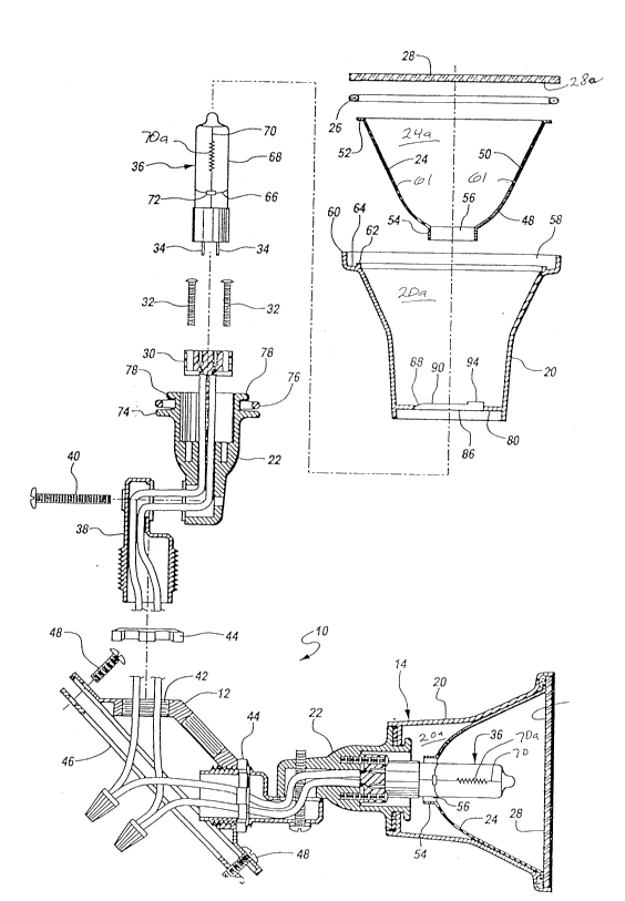
Referring initially to Fig. 1, outdoor lighting assembly 10 is shown comprising a base
plate 12 and a pair of identical lighting fixtures 14. The preferred embodiment of assembly
10 also includes a conventional motion sensor 16, the operation of which is well known to
S those skilled in the art and, therefore, need not be disclosed herein. Assembly 10 is
configured to be a direct replacement for a conventional PAR 38 assembly 18, as shown in
Fig. 2, the operation and structure of which are well known to those skilled in the art. The
various unique features contained in assembly 10 are described hereinbelow.
With reference now also to Fig. 3, each fixture 14 is shown comprising an upper
housing 20 removably securable to lower housing 22. The upper housing 20 and the lower
housing 22 are each preferably formed of die-cast zinc or aluminum because of their
desirable high thermal conductivity properties. The lower housing 22 is also preferably
formed to be of substantial mass with relatively thick walls to serve as an effective heat sick.
The lower housing 22 is further recessed under the upper housing 20 and the reflector 24 to
15 minimi7e the impact of radiant energy and overheating thereof.
When assembled in a manner described below, upper housing 20 contains reflector
24, retained by adhesive material 26, and lens 28. Lens 28 is preferably formed of tempered
glass and is generally of planar configuration. Lower housing 22 contains a receptacle 30
secured in a place by screws 32, suitable for engaging electrodes 34 extending from the
20 proximate end of lamp 36. The base end of lower housing 22 is hingedly secured to
adjustment arm 38 in a conventional manner by screw 40, with arm 38 being adjustably
retained within threaded hole 42 in base plate 12, and secured by lock nut 44. Base plate
12 is configured for attachment to structure 46, such as the exterior wall of a building, by
screws 48. As with conventional assembly 18, each fixture 14 may be rotated and angularly
25 adjusted as desired upon selective manipulation of adjustment arm 38, screw 40, and lock
nut 44.
As best seen in Fig. 3, reflector 24 is essentially cup-shaped, having a curved lower
portion 48 and a frusto-conical upper portion 50 defining a cavity 28a therewithin. Reflector
24 is open at both its top and bottom ends, with an annular flange 52 extending from the
30 perimeter of upper portion S0, and annular lip 54 extending longitudinally downwardly from
the opening 56 in lower portion 48, the function of lip 54 being described below. Reflector
21~7789
24 is preferably formed from drawn aluminum. The curved lower portion 48 is preferably
dish-shaped, having a generally parabolic cross-section.
The open face 58 of upper housing 20 is bounded by an upstanding peripheral wall60, integrally formed with side walls 61. Ridge 62 is formed inwardly from wall 60, and
5 parallel thereto, thereby forming a channel 64 around the periphery of base 58. A unique
assembly method has been devised for securing lens 28 to upper housing 20, wherein a
suitable quantity of fluid, uncured adhesive material 26 is placed within channel 64, reflector
24 then placed in position with flange 52 supported by ridge 62, and lens 28 pressed into
position within wall 60. As best seen in Fig. 4, adhesive material 26 effectively fills channel
64 and adheres the inner surface 28a of lens 28 to upper housing 20, with flange 52
sandwiched between lens 28 and ridge 62, thereby securing reflector 24. The inner surface
28a compresses the adhesive material 26 into the channel 64 and against the reflector
flange 52. Upon curing of adhesive material 26, lens 28 and reflector 24 are operatively
secured to upper housing 20, and a waterproof seal is simultaneously formed around face 58.
Adhesive material 26 is preferably a silicone rubber compound, but may be any suitable
compound adapted for the purpose.
Face 58 and lens 28 are preferably square, as shown herein. It is to be understood,
however, that face 58 and lens 28 may be round, hexagonal, or of virtually any feasible
configuration without departing from the scope of this invention.
Lamp 36 includes an internal reflector 66 operatively mounted within tubular quartz
envelope 68. Filament 70 includes a coiled section 70a and is electrically connected to
electrodes 34 in a conventional manner. Filament 70 extends longitudinally within envelope
68, passing through in~ tor 72 which prevents electrical contact between filament 70 and
reflector 66. In the preferred embodiment shown, reflector 66 has a upwardly curved
surface which generally conforms to the contour of lower curved portion 48 of reflector 24.
When assembled as shown, reflector 66 substantially fills in the gap in reflector 24 caused
by opening 56, thereby increasing the projection of light longitudinally outwardly through
the envelope 68 toward the distal end of lamp 36. Reflector 66 may be formed from
polished tungsten or any other material suitable for the purpose. Insulator 72 is preferably
formed from glass or ceramic, and serves to secure reflector 66 in its operative position
circumscribing a portion of filament 70. Aside from the inclusion of reflector 66 and
2147789
inc~ tor 72, lamp 36 is otherwise~a conventional single-ended quartz halogen lamp, but
requires no additional labor or time in assembly.
Upper housing 20 and lower housing 22 are removably interconnected through a
unique quarter turn f~ctening system. Referring now to Figs. 3 and 5, lower housing 22 has
5 an integrally formed annular shoulder 74 extending radially from the top, connecting end.
Disposed on the top surface of shoulder 74 is seal 76. A pair of keys 78, spread 180 apart,
project radially outwardly from the distal end of lower housing 22. The proximate end 80
of upper housing 20 has an opening 82 formed therein, defining a pair of keyways 84
configured to receive keys 78. As seen in Figs. 7 and 8, the inside surface of proximate end
80 has a pair of camming ramps 86 formed thereon, spaced 180 apart and disposedannularly about opening 82 and intermediate keyways 84. Each ramp 86 includes a leading
edge 88 having an inclined upper surface formed thereon, a generally flat intermediate
section 90 having a substantially horizontal upper surface formed thereon, and a trailing edge
92 having a stop 94 projecting upwardly therefrom.
Assembly of upper housing 20 onto lower housing 22 is accomplished by inserting
lamp 36 into opening 82 with keys 72 aligned with keyways 84, until proximate end 80
contacts seal 76. Slight additional longitudinal pressure causes proximate end 80 to
resiliently compress seal 76, whereupon keys 78 are positioned within upper housing 20.
The rotation of upper housing 20 (clockwise, in the preferred embodiment) slidably engages
the top surfaces of c~mming ramps 86 with the underside surfaces of keys 78, with the
rotation being limited upon keys 78 abutting stops 94. The inclined upper surfaces of leading
edges 80 axially draw together upper housing 20 and lower housing 22 and facilitate the
engagement of ramps 86 with keys 78 while the forces generated between intermediate
portion 90 and keys 78 adequately compresses the seal 78 to form a subst~ntially watertight
junction between upper housing 20 and lower housing 22. Removal of upper housing 20 is
accomplished simply by reversing the quarter-turn rotation. The relative ease of assembly
and rli~ccembly of fixture 14 greatly simplifies the replacement of lamp 36 as compared to
conventional quartz halogen floodlight fixtures.
In the preferred embodiment shown, lower housing 22 includes two keys 78, and
upper housing 22 includes a like number of keyways 84 and camming ramps 86. It will be
readily appa ent to those skilled in the art, however, that it may be possible to ôbtain
acceptable results with a different number of keys, keyways, and camming ramps. When
- 6 -
2147789
,_
constructed as shown, upper housing~20 is installed and removed by rotation through an
angle of 90, i.e., a quarter turn. Obviously, this would be affected by the number of keys,
keyways, and r~mming ramps employed.
In the preferred embodiment of this invention, the disposition of seal 76 onto the
upper surface of shoulder 74 is accomplished in a novel manner. A suitable composition of
adhesive material is deposited onto shoulder 74 and allowed to cure until the exposed surface
is no longer tacky or adhesive while the underside adheres to shoulder 74. Upper housing
20 may then be secured to lower housing 22 as described above. The same compound for
seal 76 is preferably also used for adhesive 26, thus increasing the manufacturing efficiencies
over the known prior art. In the preferred arrangement the composition for seal 76
comprises silicone rubber, suitable impregnated with nitrogen bubbles in a conventional
manner, to allow the cured material to be foamed for resilient to compression and re-use.
The amount of nitrogen will affect the resiliency of the compound in accordance with the
user's requirements. Further, in a preferred manner, such foamed adhesive is cured at room
telnpe~ re and atmosphere for approximately four hours.
As seen in Fig. 1, the corners 96 of lens 28 are preferably shaded, leaving only a
clear circular region corresponding to the opening in reflector 24 bounded by flange 52. It
has been found that tempered soda lime glass is preferable for forming lens 28, while the
shading in corners 96 comprises black ceramic fired ink applied to inner surface 28a of lens
28 by a conventional process. It is fully expected, however, that the composition and
appeal~lce of lens 28 may be altered as desired without departing from the spirit and scope
of this invention.
As mentioned above, opening 56 in lower portion 48 of reflector 24 includes a
longitudinally downwardly extending lip 54, as illustrated in Fig. 3. Upon assembly of
reflector 24 within cavity 20a of upper housing 20, opening 56 defined by annular lip 54 is
substantially aligned with opening 82 so that lamp 36 may be received and properly
positioned within reflector 24. Lip 54 circumscribes a portion of lamp 36, preferably the
exposed portion of envelope 68 beneath reflector 66. Lip 54 therefore restricts the passage
of light em~n~ting from filament 70 into cavity 20a of upper housing 20, and further assists
reflectors 24 and 66 in projecting the maximum amount of light outwardly in the desired
direction.
21~7789
-
The lip 54 also prevents light from heating the components disposed beneath the
reflector 24 by radiation from the filament 70. Accordingly, fixture 14 is capable of
operating at a lower overall housing temperature than conventional quartz halogen floodlight
fixtures. Fixture 14 also projects a beam spread of approximately 120, which isS substantially greater than the 55-60 beam spread provided by conventional PAR 38
fixtures. By combining a single ended quartz halogen lamp 36 with the uniquely formed
reflector 24, fixture 14 is capable of providing superior light projection and dispersion, a
longer life, and lower energy consumption than a conventional PAR 38 fixture. Further, the
opening 56 in the reflector 24 does not have a sharp inner edge resulting from burrs during
10 manufacturing as the projecting annular lip 54 allows for any such sharp edges to occur on
the bottom, outside edge of the lip 54. Thus, scratching of the lamp envelope during
assembly is prevented.
While the principles of an improved two-piece quartz halogen flood light assembly
have been made clear from the foregoing detailed description, it is to be understood that the
15 scope of coverage provided by this patent is to be limited only by the following claims, and
not by the specific embodiment described herein. It is also to be understood that references
herein to "top", "upper", "lower", and "side" structures are intended solely for purposes of
providing an enabling disclosure, and in no way suggest limitations regarding the operative
orientation of assembly 10 or any components thereof.