Language selection

Search

Patent 2147796 Summary

Third-party information liability

Some of the information on this Web page has been provided by external sources. The Government of Canada is not responsible for the accuracy, reliability or currency of the information supplied by external sources. Users wishing to rely upon this information should consult directly with the source of the information. Content provided by external sources is not subject to official languages, privacy and accessibility requirements.

Claims and Abstract availability

Any discrepancies in the text and image of the Claims and Abstract are due to differing posting times. Text of the Claims and Abstract are posted:

  • At the time the application is open to public inspection;
  • At the time of issue of the patent (grant).
(12) Patent: (11) CA 2147796
(54) English Title: AUTOMOTIVE HOOD STRUCTURE
(54) French Title: CAPOT D'AUTOMOBILE
Status: Expired
Bibliographic Data
(51) International Patent Classification (IPC):
  • B62D 25/12 (2006.01)
(72) Inventors :
  • KANEKO, TAKASHI (Japan)
(73) Owners :
  • SUZUKI MOTOR CORPORATION (Japan)
(71) Applicants :
(74) Agent: FETHERSTONHAUGH & CO.
(74) Associate agent:
(45) Issued: 1998-12-15
(22) Filed Date: 1995-04-25
(41) Open to Public Inspection: 1996-03-07
Examination requested: 1995-04-25
Availability of licence: N/A
(25) Language of filing: English

Patent Cooperation Treaty (PCT): No

(30) Application Priority Data:
Application No. Country/Territory Date
211648/1994 Japan 1994-09-06

Abstracts

English Abstract


An object of an automotive hood structure of the present
invention is to increase the hood strength and make it possible
to decrease the sheet thickness of a hood inner 2 without the
complicated shape of a hood inner 2 around a striker 3 or the
increased size of the striker 3. A reinforcement 4, comprising
a top flat portion 41 and flange portions 42, and the striker
3 are disposed between a hood outer 1 and the hood inner 2. A
flange portion 31a of the striker 3 is lapped on the flange
portion 42 of the reinforcement 4, and welded to the hood inner
2. The top flat portion 41 is fixedly bonded to the inside
surface of the hood outer 1.


French Abstract

La présente invention porte sur un objet dans une structure de capot d'automobile ayant pour but d'augmenter la résistance du capot et de permettre de diminuer l'épaisseur de la tôle de doublure 2 sans la forme compliquée d'une doublure de capot 2 autour d'un pêne de verrouillage 3 ou le grossissement du pêne 3. Un renfort 4, comportant une partie supérieure plane 41 et des parties rabattues 42, et le pêne de verrouillage sont placés entre un capot 1 et sa doublure 2. Une partie rabattue 31a du pêne 3 chevauche la partie rabattue 42 du renfort 4 et est soudée à la doublure 2. La partie supérieure plane 41 est fixée de façon permanente à la surface intérieure du capot 1.

Claims

Note: Claims are shown in the official language in which they were submitted.


6. CLAIMS
(1) An automotive hood structure in which a reinforcement and
a striker are disposed between a hood outer and a hood inner,
wherein said reinforcement comprises a top flat portion and
flange portions, the flange portion of said striker is lapped
on said flange portion of said reinforcement and welded to said
hood inner, and said top flat portion is fixedly bonded to the
inside surface of said hood outer.
(2) An automotive hood structure according to claim 1, wherein
said striker comprises a bracket having a flange portion and a
striker piece bonded to said bracket.
(3) An automotive hood structure according to claim 1, wherein
said top flat portion of said reinforcement is divided by a
plurality of grooves, which are used for inserting the welding
equipment.

- 9 -

Description

Note: Descriptions are shown in the official language in which they were submitted.


214779 ~


SPECIFICATION


1. TITLE OF THE INVENTION
AUTOMOTIVE HOOD STRUCTURE


2. FIELD OF THE INVENTION AND RELATED ART STATEMENT
The present invention relates to an automotive hood
structure and, more particularly, to a reinforcing structure
around a striker of hood.

For the automotive hood, the outside shape thereof is
formed by a hood outer 1 and a hood inner 2 as shown in FIG. 1.
At the center tip end of the hood inner 2, a flat portion 21 is
formed and a striker 3 is disposed thereon as shown in FIG. 5.
The striker 3 is inserted in a hole 51 of a radiator grille 5,
and locked by means of a lock member (not shown) disposed in
the hole 51.
The details of the hood structure around the striker 3
are shown in FIGS. 5 and 6. The striker 3 is made up of a
bracket 31 having flange portions 31a and a U-shaped striker
piece 32 having bases 32a for installation, which are made of
a round bar or the like, and is formed by welding the bases 32a
of the striker piece 32 to the bracket 31. The striker 3 is
disposed between the hood outer 1 and the hood inner 2. The
flange portion 31a of the bracket 31 is fixed to the inside
surface of the flat portion 21 of the hood inner 2 so that the

21~779~


striker piece 32 protrudes downward from the hood inner 2.
As the weight of automobile is decreased, the thickness
of sheet of the hood inner 2 is made smaller. The smaller
thickness of hood inner 2 results in the shortage of strength
especially around the striker 3 to which an excessive force is
applied when the hood is closed. Therefore, the deformation of
hood inner 2, or the deformation or falling of striker 3 may
occur.
For this reason, the shape of the hood inner must be
complicated to increase the stiffness thereof, or the diameter
of the base 32a of the striker piece 32 must be increased to
enhance the installation strength of the striker 3.
Japanese Patent Provisional Publication No. 4-372475 (No.
372475/1992) has disclosed a hood structure in which a
reinforcement is disposed between the hood outer and the hood
inner, and a striker is installed on the hood inner.


3. OBJECT AND SUMMARY OF THE INVENTION
An object of the present invention is provide an
automotive hood structure in which the hood strength is
increased the sheet thickness of a hood inner can be decreased
without the complicated shape of the hood inner or the
increased size of a striker.
To solve the above problems, in an automotive hood
structure in which a reinforcement and a striker are disposed


-- 2

21477~


between a hood inner and a hood outer, the reinforcement
comprises a top flat portion and flange portions, the flange
portion of the striker is lapped on the flange portion of the
reinforcement, and welded to the hood inner, and the top flat
portion of the reinforcement is fixedly bonded to the inside
surface of the hood outer.
In the automotive hood structure of the present
invention, the top flat portion of the reinforcement is fixedly
bonded to the inside surface of the hood outer, so that the
force from the striker is distributed to the hood outer.
Therefore, the strength is increased. Also, since a closed
cross section structure is formed by the reinforcement and a
bracket of the striker, the installation strength of the
striker is increased.
Further scope of applicability of the present invention
will become apparent from the detailed description given
hereinafter.
However, it should be understood that the detailed
description and specific examples, while indicating preferred
embodiments of the invention, are given by way of illustration
only, since various changes and modifications within the spirit
and scope of the invention will become apparent to those
skilled in the art from this detailed description.


4. BRIEF DESCRIPTION OF THE DRAWINGS

21477~


The present invention will become more fully understood
from the detailed description given hereinbelow and the
accompanying drawings which are given by way of illustration
only, and thus are not limitative of the present invention and
wherein:
FIG. 1 is a perspective view of an automobile to which
the hood structure of the present invention is applied;
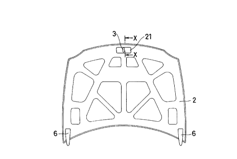
FIG. 2 is a plan view of the inside of hood in the hood
structure of the present invention;
FIG. 3 is an enlarged sectional view taken along the line
X-X of FIG. 2;
FIG. 4 is an exploded perspective view showing the
installation construction of a striker of the present
invention;
FIG. 5 is a sectional view, the same as FIG. 3, showing
a conventional hood structure; and
FIG. 6 is a perspective view of a striker used in a
conventional hood structure.


5. DETAILED DESCRIPTION OF PREFERRED EMBODIMENTS
The embodiment of the present invention will be described
below with reference to the drawings.
The automotive hood, whose outside shape is formed by a
hood outer 1 and a hood inner 2, is installed to a body 7 of
automobile via opening/closing members 6. At the center tip

21477~1~


end of the hood inner 2, a striker 3 is disposed. The striker
piece 32 of the striker 3 is inserted in a hole 51 formed in a
radiator grille S, and locked by means of a lock member (not
shown) on the inside when the car is running.
FIG. 3 is a sectional view taken along the line X-X of
FIG. 2, showing the structure around the striker 3 at the
center tip end of the hood. At the center tip end of the hood
inner 2, a flat portion 21 is formed, and at the center of the
flat portion 21, an opening 21a is formed to dispose the
striker 3 in such a manner as to protrude downward.
The striker 3 is made up of a bracket 31 and a striker
piece 32. The bracket 31 comprises a flange portion 31a and
wall portions 31b for supporting the striker piece 32 installed
at the center of the bracket 31. The striker 32 is formed by
a U-shaped round bar or the like, and the upper end thereof is
fixedly supported by the wall portions 31b of the bracket 31 by
welding or by other methods.
The striker 3 is fixed to the hood inner 2 and a
reinforcement 4 via the flange portion 31a by welding.
The reinforcement 4 is formed with flange portions 42 at
both ends, rise portions 45 on both sides, and a top flat
portion 41 protruding at the center by sheet metal pressing.
The top flat portion 41 is divided into three by grooves 43.
At the center of the flange portion 42, a step portion 42a is
formed to lap the flange portion 31a of the striker 3 (refer to

21477~


FIG. 4).
Next, the installation construction of the striker 3 will
be described with reference to FIG. 4.
The striker piece 32 is fixed to the wall portions 31b of
the bracket 31 by welding with the striker piece facing
downward. The flange portion 31a of the striker 3 is lapped on
the step portion 42a of the flange portion 42 from the lower
side of the reinforcement 4. With the flange portion 31a being
lapped on the flange portion 42a, both flange portions 31a and
42a are fixed to each other by welding (A) so that a closed
cross section structure is formed by the striker 3 and the
reinforcement 4.
The striker 3 is inserted in the opening 21a formed at
the flat portion 21 of the hood inner 2, and the flange
portions 42 of the reinforcement 4 are fixed to the hood inner
21 by welding (B). The flange portion 31a of the striker 3 is
welded (C) to the flat portion 21 of the hood inner 2. At this
time, the welding equipment for spot welding is inserted into
the welding places (C) through the grooves 43 provided on the
top flat portion 41 of the reinforcement 4.
Finally, adhesive 44 is applied to the top flat portion
41 of the reinforcement 4. With the top flat portion 41 being
bonded to the inside surface of the hood outer 1, the hood
inner 2 is mounted to the hood outer 1, and the peripheral
portion 22 of the hood inner 2 is folded and welded at the

21~77~


peripheral portion 11 of the hood outer 1.
In this embodiment, a closed cross section structure is
formed by lapping the striker 3 on the reinforcement 4, so that
the stiffness is increased, by which deformation is prevented.
5Also, the striker 3 is fixed to the hood inner 2 via the
flange portion 3la, and also fixed to the hood outer 1 via the
reinforcement 4. Therefore, the shock caused when the hood is
close is distributed to the hood inner 2 and the hood outer l,
so that the deformation of the hood inner 2 and the striker 3
10decreases. As a result, if the sheet thickness of hood is
small, the deformation of the hood inner 2, or the deformation
or falling of the striker 3 does not occur.
Further, in the case where the clearance between the hood
outer 1 and the hood inner 2 differs around the striker 3 on
15another automobile with a different hood shape, the striker 3
can be used without changing the shape thereof by changing the
height etc. of the reinforcement 4, which is easily fabricated.
Therefore, the common use of part can be effected easily.
As seen from the above description, the force from the
20striker 3 is distributed to the hood outer 1, so that the
strength is increased. Also, a closed cross section structure
is formed by the reinforcement 4 and the striker 3. Therefore,
an automotive hood structure can be provided in which the sheet
thickness of the hood inner 2 can be decreased without the
25complicated shape of the hood inner 2 or the increased size of

21~7796


the striker 3.
The invention being thus described, it will be obvious
that the same may be varied in many ways. Such variations are
not to be regarded as a departure from the spirit and scope of
the invention, and all such modifications as would be obvious
to one skilled in the art are intended to be included within
the scope of the following claims.


Representative Drawing
A single figure which represents the drawing illustrating the invention.
Administrative Status

For a clearer understanding of the status of the application/patent presented on this page, the site Disclaimer , as well as the definitions for Patent , Administrative Status , Maintenance Fee  and Payment History  should be consulted.

Administrative Status

Title Date
Forecasted Issue Date 1998-12-15
(22) Filed 1995-04-25
Examination Requested 1995-04-25
(41) Open to Public Inspection 1996-03-07
(45) Issued 1998-12-15
Expired 2015-04-27

Abandonment History

There is no abandonment history.

Payment History

Fee Type Anniversary Year Due Date Amount Paid Paid Date
Application Fee $0.00 1995-04-25
Registration of a document - section 124 $0.00 1995-11-23
Maintenance Fee - Application - New Act 2 1997-04-25 $100.00 1997-03-07
Maintenance Fee - Application - New Act 3 1998-04-27 $100.00 1998-02-27
Final Fee $300.00 1998-07-29
Maintenance Fee - Patent - New Act 4 1999-04-26 $100.00 1999-02-23
Maintenance Fee - Patent - New Act 5 2000-04-25 $150.00 2000-03-16
Maintenance Fee - Patent - New Act 6 2001-04-25 $150.00 2001-03-16
Maintenance Fee - Patent - New Act 7 2002-04-25 $150.00 2002-03-18
Maintenance Fee - Patent - New Act 8 2003-04-25 $150.00 2003-03-17
Maintenance Fee - Patent - New Act 9 2004-04-26 $200.00 2004-03-17
Maintenance Fee - Patent - New Act 10 2005-04-25 $250.00 2005-03-07
Maintenance Fee - Patent - New Act 11 2006-04-25 $250.00 2006-03-06
Maintenance Fee - Patent - New Act 12 2007-04-25 $250.00 2007-03-08
Maintenance Fee - Patent - New Act 13 2008-04-25 $250.00 2008-03-07
Maintenance Fee - Patent - New Act 14 2009-04-27 $250.00 2009-03-16
Maintenance Fee - Patent - New Act 15 2010-04-26 $450.00 2010-03-19
Maintenance Fee - Patent - New Act 16 2011-04-26 $450.00 2011-03-09
Maintenance Fee - Patent - New Act 17 2012-04-25 $450.00 2012-03-14
Maintenance Fee - Patent - New Act 18 2013-04-25 $450.00 2013-03-14
Maintenance Fee - Patent - New Act 19 2014-04-25 $450.00 2014-03-12
Owners on Record

Note: Records showing the ownership history in alphabetical order.

Current Owners on Record
SUZUKI MOTOR CORPORATION
Past Owners on Record
KANEKO, TAKASHI
Past Owners that do not appear in the "Owners on Record" listing will appear in other documentation within the application.
Documents

To view selected files, please enter reCAPTCHA code :


To view images, click a link in the Document Description column. To download the documents, select one or more checkboxes in the first column and then click the "Download Selected in PDF format (Zip Archive)" or the "Download Selected as Single PDF" button.

List of published and non-published patent-specific documents on the CPD .

If you have any difficulty accessing content, you can call the Client Service Centre at 1-866-997-1936 or send them an e-mail at CIPO Client Service Centre.


Document
Description 
Date
(yyyy-mm-dd) 
Number of pages   Size of Image (KB) 
Cover Page 1998-12-14 1 42
Cover Page 1996-04-29 1 16
Abstract 1996-03-07 1 17
Description 1996-03-07 8 244
Claims 1996-03-07 1 22
Drawings 1996-03-07 4 81
Representative Drawing 1998-04-16 1 11
Representative Drawing 1998-12-14 1 7
Correspondence 1998-07-29 1 39
Fees 1997-03-07 1 50
Office Letter 1995-11-23 1 29
Office Letter 1995-04-25 1 30
Office Letter 1995-06-07 1 22
Office Letter 1998-05-14 1 76
Correspondence Related to Formalities 1995-06-14 1 43