Language selection

Search

Patent 2148009 Summary

Third-party information liability

Some of the information on this Web page has been provided by external sources. The Government of Canada is not responsible for the accuracy, reliability or currency of the information supplied by external sources. Users wishing to rely upon this information should consult directly with the source of the information. Content provided by external sources is not subject to official languages, privacy and accessibility requirements.

Claims and Abstract availability

Any discrepancies in the text and image of the Claims and Abstract are due to differing posting times. Text of the Claims and Abstract are posted:

  • At the time the application is open to public inspection;
  • At the time of issue of the patent (grant).
(12) Patent: (11) CA 2148009
(54) English Title: APPARATUS FOR REDUCING IMPACTS ON A HARD DISK ASSEMBLY
(54) French Title: DISPOSITIF POUR REDUIRE LES IMPACTS SUR UN MECANISME D'ENTRAINEMENT DE DISQUE RIGIDE
Status: Deemed expired
Bibliographic Data
(51) International Patent Classification (IPC):
  • G11B 33/08 (2006.01)
  • G11B 33/12 (2006.01)
(72) Inventors :
  • BANG, KUG-HYEON (Republic of Korea)
(73) Owners :
  • SAMSUNG ELECTRONICS CO., LTD. (Republic of Korea)
(71) Applicants :
(74) Agent: R. WILLIAM WRAY & ASSOCIATES
(74) Associate agent:
(45) Issued: 1998-06-16
(22) Filed Date: 1995-04-27
(41) Open to Public Inspection: 1995-10-28
Examination requested: 1995-04-27
Availability of licence: N/A
(25) Language of filing: English

Patent Cooperation Treaty (PCT): No

(30) Application Priority Data:
Application No. Country/Territory Date
9021/1994 Republic of Korea 1994-04-27

Abstracts

English Abstract


An apparatus for reducing impact upon a hard disk assembly in a hard disk drive includes: an
upper frame, a lower frame, slots arcuately formed within corners of the upper frame and the lower
frame, and elastic elements for buffering the hard disk assembly from impact. Each one of the elastic
elements has a hole formed at a center portion and is inserted into the slots formed in the corners of the
upper frame and the lower frame. Contact surfaces and arcuate recesses are provided at upper and lower
portions of the corners of the hard disk assembly to accomodate installation of the elastic elements. A
fastener attached the elastic elements, the hard disk assembly, the upper frame and the lower frame
together such that neither the upper frame nor the lower frame contacts the hard disk assembly.


French Abstract

Appareil pour réduire l'impact sur un ensemble disque dur dans un lecteur à disque dur et comprenant : un bâti supérieur, un bâti inférieur, des fentes en angle formées dans les coins du bâti supérieur et du bâti inférieur et des éléments élastiques servant de tampon à l'ensemble disque dur en cas d'impact. Chaque élément élastique comporte un orifice dans sa partie centrale et est introduit dans les fentes fermées dans les coins du bâti supérieur et du bâti inférieur. Des surfaces de contact et les retraits en forme d'arc sont prévus aux parties supérieures et inférieures des coins de l'ensemble de disque dur pour permettre l'installation des éléments élastiques. Une fixation attache les éléments élastiques, l'ensemble disque dur, le bâti supérieur et le bâti inférieur de sorte que ni le bâti supérieur ni le bâti inférieur ne viennent en contact avec l'ensemble disque dur.

Claims

Note: Claims are shown in the official language in which they were submitted.


WHAT IS CLAIMED IS:


1. An apparatus for reducing impact upon a hard disk assembly in a hard disk drive, said
apparatus comprising:
an upper frame installed at an upper portion of said hard disk assembly and a lower frame
installed at a lower portion of said hard disk assembly; and
a plurality of elastic elements for buffering said hard disk assembly from said impact, said elastic
elements installed at corners of said upper and lower frames between said upper frame and said hard disk
assembly and further between said lower frame and said hard disk assembly.

2. The apparatus of claim 1, further comprised of said upper frame and said lower frame
having an identical shape.


3. The apparatus of claim 2, further comprised of said upper frame and said lower frame
having a rectangular shape.


4. The apparatus of claim 1, further comprised of said upper frame comprising first slot
portions arcuately formed in the corners of said upper frame for accommodating placement of said elastic
elements between said upper frame and said hard disk assembly.


5. The apparatus of claim 4, further comprised of said lower frame comprising second slot


portions arcuately formed in the corners of said lower frame for accommodating placement of said elastic
elements between said lower frame and said hard disk assembly.


6. The apparatus of claim 5, further comprised of said plurality of elastic elements being
selected from among the group comprising rubber and pulpwood.


7. The apparatus of claim 1, further comprised of said plurality of elastic elements being
selected from among the group comprising rubber and pulpwood.


8. The apparatus of claim 1, further comprised of said elastic elements preventing contact
between said upper frame and said hard disk assembly and further preventing contact between said lower
frame and said hard disk assembly when said upper frame, said lower frame and said hard disk assembly
are assembled into a unitary structure.


9. An apparatus for reducing impact upon a hard disk assembly in a hard disk drive, said
apparatus comprising:
an upper frame;
a lower frame;
slots arcuately formed at corners of said upper frame and said lower frame;
elastic elements for buffering the impacts, each one of said elastic elements having a hole formed
at a center portion, said elastic elements being positioned within said slots arcuately formed at said


corners of said upper frame and said lower frame;
recesses arcuately formed at corners of said hard disk assembly for accommodating installation
of said elastic elements at upper and lower portions of said corners of said hard disk assembly; and
fastening means for attaching said elastic elements, said hard disk assembly, said lower frame
and said upper frame together into a unitary structure so that said hard disk assembly has no direct
contact with said upper frame and said lower frame.


10. The apparatus of claim 9, further comprising:
said upper frame having a rectangular shape and being installed around an upper peripheral
surface of said hard disk assembly;
said lower frame having said rectangular shape and being installed around a lower peripheral
surface of said hard disk assembly; and
said upper and lower frames respectively covering said upper and lower portions of said corners
of said hard disk assembly with no direct contact between said upper frame and said lower frame.


11. The apparatus of claim 9, further comprised of said elastic elements being selected from
among the group comprising rubber and pulpwood.


12. The apparatus of claim 9, further comprised of said unitary structure being configured
so that said corners of said hard disk assembly are aligned with said corners of said upper and lower
frames.


11


13. A method of manufacturing an apparatus for reducing upon a hard disk assembly,
comprising the steps of:
forming a lower frame comprising first arcuate recesses formed within corners of said lower
frame, said lower frame having a shape that extends co-extensively with an outer periphery of said hard
disk assembly;
forming an upper frame comprising second arcuate recesses formed within corners of said upper
frame, said upper frame having said shape that extends co-extensively with said outer periphery of said
hard disk assembly; and
forming said hard disk assembly comprising third arcuate recesses formed within upper corners
of said hard disk assembly and fourth arcuate recesses formed within lower corners of said hard disk
assembly, said hard disk assembly further comprising a contact surface positioned between and
separating said third and fourth arcuate recesses.


14. A method of assembling said apparatus of claim 13, comprising the steps of:
inserting first elastic elements into said first arcuate recesses formed within said corners of said
lower frame;
placing said hard disk assembly upon said first elastic elements with said corners of said hard
disk assembly in alignment with said corners of said lower frame, said first elastic elements being
positioned within said fourth arcuate recesses formed within said lower corners of said hard disk
assembly;
12


placing second elastic elements upon an upper portion of said contact surface of said hard disk
assembly, said second elastic elements positioned within said third arcuate recesses formed within said
upper corners of said hard disk assembly; and
placing said upper frame upon said second elastic elements with said second elastic elements
positioned within said second arcuate recesses of said upper frame, said corners of said upper frame
being in alignment with said corners of said hard disk assembly.


15. The method for assembling said apparatus of claim 14, further comprising a step of:
inserting fastening members sequentially through said corners of said upper frame, said second
elastic elements, said contact surfaces of said hard disk assembly, said first elastic elements and said
corners of said lower frame to assemble said lower frame, said first elastic elements, said hard disk
assembly, said second elastic elements and said upper frame as a unitary structure.


16. The method for assembling said apparatus of claim 15, further comprised of said lower
frame, said first elastic elements, said hard disk assembly, said second elastic elements and said upper
frame being assembly as said unitary structure without any contact between said upper frame and said
hard disk assembly and between said lower frame and said hard disk assembly.


13

Description

Note: Descriptions are shown in the official language in which they were submitted.


2~48009


B~CKG~OUND OF T~ I~ TlOrl


o Thc present in~cntion relatcs to an apparatus fo~ redua~g the likelihood of dam~g~ to a hard di_k
assembly due to physical shock and sudden impact, and morc par~cularly to an apparatus fitted wit~
elastic clçn~P~t~ for bu~fering cxterDal impa~tC at cach of the comers oE lhe hard disk ~cs~nbly


Generally, a h~d disk dri~c pcrforms thc filnr ion of recording and reprodu~np i~formation
s stor~d in a rn~etic rnemory de~/ice Such dri-/~ typically include a spindlc motor for rot~ g a disk
upon which data is stored at a constant specd, a m~gnetic head ~or tecording and reproducing the data

214800~3


onto and ~m the disk, an a0uator havingthe ~ ;r hcad jnct~ at onc end foJ c~b!i~ .c,~
of thc m~Ph~ head, and a voice coil motor for ~n *lir~ thc ~lu~nr to bc dri en.


The actuator rotat~; about a pivot and has a bobbi~ nr~ at another end ol,~sile the
m~ C head. n~e ac~uator moves by a rc~tio~ ~ force appUed to thc a~ via the voice aoil motor,
s there~y enabl~ng the m~eti~ head positio~ at one end of thc actuator to move aaoss the surfaoe of
the disk to record and rc~-oduce data onto and ~om ba~cs on the disk.


In ahard disk drive, in order tosatis~ the need for .- i~ ~tion and low powu co~.s~ pt;on,
it has been r.~ to reduce the height of thc hard disk ~sembly from a ~,~ie-~innq~ hei~bt of about
42 mm, to below 1 inch. When the hard disk dnve is min~ ; descnbed above, ~w~ , it
~o ~"~rs ~ncrea~ingly susoeptible to physical damage prima~ily due to cont_ct between the a~t~,r and
the surface of the disk as a result of shoc~s and impacts whcn mis~ t during shippin~ o~ h~n-lling
by a~- c- .~ , thereby causirlg the disk drivoe to experience an i~ ault ratc. ~urthc~ore,
h~~ on of the hard disk drive inberently ro~uu~ that the si~e of the spindle motor and a bearing
used in thc hard disk drivc be reduced. Accordingly, the hard disk drive has a very lo~ re~cictq~ e to
~5 c~ternql imr~ctc,


To solve thcse problems, I have discovered that it has bccome r~ to provide a s4uchue
c~pable of bu~eting the hard disk assembly ~rom damage likely to be caused by e~tt~r ~1 imp~s. One
recent cffort at ~ea~ng such a stmctu~e is ~ sc~ in U.S. ~atent No. 5,402,308 entitled Port~ble D~k
Stwage Apparan~ ~Jsing Ft~ibte Cable For Shock Absorps~on issued to Royanagi et al. on 28 March


z

2~80~9


1995. ln this m~ention, a dislc storage u~t i~ a rotatable disk a~d a head ~ to( is ~uppo~t~d by
sho~ ~90~1s withim a prote ~ e outer case. While thi~ UI;o~ pU~ S to prcr~ nSçnti ny
sho~roof en~w.L.~Q ~or thc disk storage unit, I believe tha~ t;onal designs such as that sh~n
m ~oyanagi et al. ~ be si~npl~fied and i-"t,.o~

~UMMA~Y ~F THF ~NVF~FIO~


Acoordingly, it is an object of the present invention to provide an i~p.oved appaldll~., for
r~cillg shocks and impacts in a hard disk ~sen~bly.
lt is another object to pro~ide an app~dlus for rcducing damage to a hard disk drive that resul~
f~o~ external irnp~cts.
It is s~ll an~ther o~ect to pro~ide an ay~at~s for ~l~sunng that no direct impact be exerted upon
the hard disk ~selT~bly.
It is ye~ another objcct to pro~dc an a~lus for ~uI~e. ~g impacts inflicted upan the hard disk
assembly.
~e and othcr objeas may be a~lu~!~ with an d})pdldlus constIucted according to the rulciples
of the preseQt ~ e.~lion w~ upper frame, a lower Same, slots arcuately formed in each of the co~De~s
of the upper f~amc and thc lower ~ame, and clastic rl~ s for l~uU~,~ulg thc hard disk ~se ..bl~ against
damage duc to c~nqlly a~inictered ;~ Each one of the elastic ele.J~ ts has a hole formed at
a center portion and is fitted into the slots arcuately formed at each of the c~rners of the upper frame and
20 thc lower ~ame. A contact su~fac~ is provided at upper and lower portions of each of the corners o~ the
hard disk assembly to further accu~ ..odate in~t~ tion of the elastic ClCI~ ltS. A fastener att~hps thc


214~0D9


elastic c~ .ts, the hard disk a~e~bly, tbe uppcr ~ne and the lowcr ~ame togcther in a uni~y
WG such that neithcr the upper ~rame nor ~c lower hame direcsly c~r~ the hard disk ~ .bly.


P~R~FF nF~C~Or~ OF l~F nR~


A r~ore c~mplete appre~tion of the invention, and many of the ~ t advantages thereof,
5 will be readily app~ent ~s the same b~)~nes better undcrstood by rcference to the following detailed
des~ip~on when c~-rci~ered in c~njwl~ioll with the acc~ ih~g drawings, in which like ref~rence
symbols indicate the same or simila~ eor~ ..eu~s, whcreiD:
Flg. 1 is a p~ e ~riew illualldtulg a hird disk drive in which elastic elements for reducing
irnpacts aJe inct~15d on a hard disk assembly constructed acc~rding to the principles of the present
10 i~vention;
Flg. ~ is a ~a~li~c vi~w i~ g main portions of the l~d disk drive consl~ ;led according
to the principles of the present invention; and
Flg. 3 is an exploded pe~s~li~c view i~ dlillg a hasd disk assembly c~nst~ucted acc~.ding
to the principles o~ thc present inventio~.


n~A~ .F,n nFASCRlmON OF THF, PRF,FFRRFIl F,~Ron~MF,~T


Turning ~ow to the drawings and referring to Figs. 1 and 2, the hard dislc drive 1 co~âtructed
according to the pnnciples o~ the present invention will be dcacribed.


214800~


In ha~d disk drive 1, slo~s 3a and 4a are ~hl~ formed on the comcrs of a~ upper framc 3 aDd
a lowe~ frame 4, respec~vely, Upper f~ame 3 h~ing a rc~,-g~llar shape is c~nfigurcd for inc~ tion 0~
an upper portion of hard dlsk assembly 2, while lower ~ame 4 having the same r~ang~lar shape as
upper fJame 3 is o~gu.~ for inchll~ioIl on a lower portion of hard dis~ ~ss~nhlr 2. Elas~dc el~nentc
s 5 for ~u~ g impac~s are in~llod ~lw~ upper frame 3 and hard disk assembly 2, and also ~lweeu
lower frame 4 and bard disk ~se~nbly 2. Each elastic element S has a height tl that is greater than a
height t2 of slots 3a and 4a, and is provided with a hole 6 at a oenter p~rtion. A contact sur~e 2a and
an arcuate recess 2b for ~ .nodating inct~ tjon of a cc l~nding elastic elemcnt 5 are provided
at upper and lower portions of each of the comers of the hard disk asse~bl~ 2. Each elastic elc~e~t S
is inserted into sl~ts 3a and 4a formed at the com~rs of upper fr~ne 3 and lower frame 4, res~ely.
At ea~h of the come~s, a screw 7 is sequcn~ially p~ssed through upper ~rame 3, hole 6 of elas~c ~lement
S s~dl~g upper ~ame 3 and hard disk assembly Z, contact ~r~ 2a of hard disk ~se~l~ly 2, hole
6 of elastic elc,~.c.ll 5 separating lowcr frame 4 and hard disk assembly 2, and lower frame 4.


Each elastic element S bas a cglindlical shape and is c~mposed of an elas~c material, such as
mbber or pulpwood, which is capable of bufre.ing impacts. Ihc hcight t~ of each elastic clement 5 is
greater tha~ the height t2 of sl~ts 3a and 4a of upper and lower ~ames 3 a~d 4, r~s~c.liv~ ly. Each elas~dc
clement 5 also has a thiel~nP~s t3 that is su~icient to prevent c~ntact ~ a hard dislc ~cs~mbly 2 a~d
upper and lower ~ames 3 and 4, r~spe~


Operation of hard d-~k drive 1 constructed according to thc principles of the present inventio~
20 as described abo~rc will now be described in detail.


s

21'18009


With ~e de~ek~ of s~ , the nu~ber of ~t~ t~ cuc-lits (1(~) u~
in ha~d disk drivc 1 and tbe sizc of a printed circuit sub~ te can be ac~rd~ly r~ccd. T~c,.efor~" the
height of ha~d disk aCs~ y 2 can be rcduced to about onc ~alf o~ an inch ~ Glses whcre the p~ted
circuit substrate is jnct~ ard disk ~csen~hly 2. In the present invenffon, elastic ck.n~ 5 are
5 jn~ l~ at c~n~ su~oeS 2a for~ed on uppc!r a~d lower portioDs of the comers of ~rd disk assembly
2 and sre inserted into slots 3a and 4a fonned r~ ely at the corness of upper ~ame 3 a~d lower
fiame 4. Once upper and lower fiamcs 3 a~d 4, elastic cle~el,~ 5 a~d hard disk ~ ~bly 2 are p~pe,l~
aligned, screw 7 is at cach o~e of the comcrs sequcn~ally passed thlough a fixing hole in upper frame
3, ~ole 6 of e~ic elcment 5 u~ ed betwcen upper ~ame 3 and hard disk ~ssell,bly 2, contact surfaces
lO 2a of hard disk accembly 2, and hole 6 of cla~c elemeDt 5 ins,allcd bet~. ~u lower ~ame 4 and hard disk
a~ nbty, thcrcby enabling screw 7 to be fixedly secared to lower ~ame 4. Since upper fiame 3 and
lo~er fiame 4 co~r upper and lower p~ripheral ~u~rac~s of hard disk asse~Pbly 2, resp~li~ , with no
dir~ct consact h~w~n each other and hard disk assembly ~, external impacts arc e~ cly absorbed
by clastic elements 5 jnCt?ll~d at contact surfaces 2a fo~med on the upper and lower portio~s of the
~s comer.s of hard disk ass~bly 2, even thol~gb the impa~ arc t~d~s~itted directly to upper ~De 3 a~d/or
lo~ver fr~e 4. ~c~~ ly, hard disk assembly 2 is advantageously ~lote~ d from extt~ql imp~


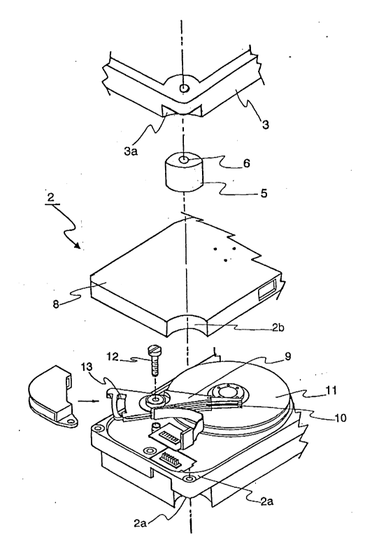
ReferTing ww to Flg. 3, an c~cploded F~ls~Sive view ill~llatillg thc co~ on l~h.~ecn hard
dis!~ assembly 2, elastic elcment 5 and uppcr ftamc 3 constructed according to the principles of the
preseDt iuvention is sho~vn. Slot 3a of upper frame 3 ~ odates inst~1lq,t;on of el stic elemeDt 5 in
a manner such that thae is alignment ~., hole 6 of elastic element 5 and a holc (an unnumbered

feature) formed in upper f~ame 3. Hard disk assembly 2 has a cover 8 for eaclosiag and protectiag the


2148009


intcrnal c~ r.~ of hard d;sk q~sç~bly ~ 1 hesc interDal c~u.ponc,~ clude an a~uator arm 9
having a m~e~;ç head 10 fonned at one end pordon of a~ or arm 9 for ~f~i~lg and Ic~ lue;"g
data onto and from ~ cs formed on a memory disk 11. Actuator arm 9 is scc~ed to a b~;e portion of
ha~d disk assembly 2 via a fastener 12 to cnable rotation of a~ or arm 4 aDd movement of nl~etic
5 head 10 aaoss t~e sur~e of di~k 11. Rotat;on of a~iuato~ an~ 4 is acti-~at~d through a voicc coil motor
13 i~C~tI~d at the other end po~tio~ of ac~ or a~m 4. In PC~nce, Fig 3 sho~s thosc elements w~ich are
holJsed wi~ hard disk asse~l~ 2, and are hig~ly s~I~xptl~lc to darnage if an cxtemal impac~ is appUed
directly to the ~c~e~nbly. With the present invention, howe~cr, when hard disk d~ive 1 ~l~u~l~ as
d~scnbed abovc falls or is d~opped by an individual, impact tl~.r.c...ilI~,i to hard disk assembly 2 L
~o ~ i sinc~ upper hame 3 and/or lower frame 4 first recei~es the direct impac~. Fur~hcl~uo~e, since
thc impacS L~r.cl~ill~ to uppc~ ~arne 3 and/or lo~er ~rame 4 is buffered by each of thc elastic elçrnents
5 fixed at the uppet and lower portions of the c~r~ers of hard disk ~c~P-nhly 2, impacts l~ ed to
voice coil motor 13, the spindle motor of disk 1~, f~tcner 12 and actuatot arm 9 installed in hard disk
assembly 2 are also mitigate~, thereby pl~r~ ulu~g damagc to thc disk li and the magnetic he~d 10
instaUed at actuator a~T~ 9.

Ihe present i~ve.~lion can be ~f~rier tly n~nuf~ red by fo~m~n~ upper and lower ftarnes 3 and
4 with a~cuatc slot~ 3a and 4a formed within each of their r~C(iv~ comers a~d with shapes that extend
oo e~le~i~ely with an outer pcriphery of hard disk assembly 2. Hard disk assembly 2 is ~ nlIf~l t~
by forn~ing aralatc re~esscs 2b within ~oth upper and lowcr corners and con~act surfaces 2a positioned
20 between and Scpd.~ing the uppcr and lower comers of hard disk ~ccpn~bly ~ This simplifed, yet highly
effective, dcsign enables easy and quick assembly by alignrnent of the ~rarious components and ilLcertion


214~0~9


of ~astt~c~ 7, as dcpicted in Flg. ~


As des~d above, thc present i~ liuu ~rov;des shoc~ ab~,l"ng f~ames at upper and lo~ver
portions of a hard disk drivc as~embly, and elastic cle~llen~ for buffering illlpd~ e ~ W at ~e
corners of the ~ard disk a~mbly. l~e.e~o-e, when externat impac~s or shocks occ~ c pres~nt
s invention provides an ad~ t~gc in that the ~ard disk a~s4n-bty can be plot~l~l So~ the impacls a~d
the risk of dam~ge to thc ~ tic head or the disk can be signifi~ ly reduc~d.


Representative Drawing
A single figure which represents the drawing illustrating the invention.
Administrative Status

For a clearer understanding of the status of the application/patent presented on this page, the site Disclaimer , as well as the definitions for Patent , Administrative Status , Maintenance Fee  and Payment History  should be consulted.

Administrative Status

Title Date
Forecasted Issue Date 1998-06-16
(22) Filed 1995-04-27
Examination Requested 1995-04-27
(41) Open to Public Inspection 1995-10-28
(45) Issued 1998-06-16
Deemed Expired 2014-04-29

Abandonment History

There is no abandonment history.

Payment History

Fee Type Anniversary Year Due Date Amount Paid Paid Date
Application Fee $0.00 1995-04-27
Registration of a document - section 124 $0.00 1996-04-11
Maintenance Fee - Application - New Act 2 1997-04-28 $100.00 1997-04-24
Final Fee $300.00 1998-01-20
Maintenance Fee - Application - New Act 3 1998-04-27 $100.00 1998-04-27
Maintenance Fee - Patent - New Act 4 1999-04-27 $100.00 1999-03-26
Maintenance Fee - Patent - New Act 5 2000-04-27 $150.00 2000-03-16
Maintenance Fee - Patent - New Act 6 2001-04-27 $150.00 2001-03-16
Maintenance Fee - Patent - New Act 7 2002-04-29 $150.00 2002-03-18
Maintenance Fee - Patent - New Act 8 2003-04-28 $150.00 2003-03-17
Maintenance Fee - Patent - New Act 9 2004-04-27 $200.00 2004-03-17
Maintenance Fee - Patent - New Act 10 2005-04-27 $250.00 2005-03-07
Maintenance Fee - Patent - New Act 11 2006-04-27 $250.00 2006-03-06
Maintenance Fee - Patent - New Act 12 2007-04-27 $250.00 2007-03-08
Maintenance Fee - Patent - New Act 13 2008-04-28 $250.00 2008-03-07
Maintenance Fee - Patent - New Act 14 2009-04-27 $250.00 2009-03-26
Maintenance Fee - Patent - New Act 15 2010-04-27 $450.00 2010-03-24
Maintenance Fee - Patent - New Act 16 2011-04-27 $450.00 2011-03-24
Maintenance Fee - Patent - New Act 17 2012-04-27 $450.00 2012-03-30
Owners on Record

Note: Records showing the ownership history in alphabetical order.

Current Owners on Record
SAMSUNG ELECTRONICS CO., LTD.
Past Owners on Record
BANG, KUG-HYEON
Past Owners that do not appear in the "Owners on Record" listing will appear in other documentation within the application.
Documents

To view selected files, please enter reCAPTCHA code :


To view images, click a link in the Document Description column. To download the documents, select one or more checkboxes in the first column and then click the "Download Selected in PDF format (Zip Archive)" or the "Download Selected as Single PDF" button.

List of published and non-published patent-specific documents on the CPD .

If you have any difficulty accessing content, you can call the Client Service Centre at 1-866-997-1936 or send them an e-mail at CIPO Client Service Centre.


Document
Description 
Date
(yyyy-mm-dd) 
Number of pages   Size of Image (KB) 
Representative Drawing 1998-06-09 1 8
Abstract 1995-10-28 1 20
Cover Page 1995-12-14 1 17
Description 1995-10-28 8 273
Claims 1995-10-28 6 152
Drawings 1995-10-28 3 53
Description 1997-05-28 8 265
Claims 1997-05-28 5 147
Cover Page 1998-06-09 2 61
Representative Drawing 1998-06-18 1 23
Correspondence 1998-01-20 1 42
Prosecution Correspondence 1995-04-27 5 169
Office Letter 1995-06-07 1 15
Examiner Requisition 1996-07-03 2 62
Prosecution Correspondence 1996-11-04 3 89
Prosecution Correspondence 1996-11-04 7 420
Fees 1997-04-24 1 53