Note: Descriptions are shown in the official language in which they were submitted.
P 1 n5~1 ~i
214806
Specification
Title of the Invention
Method and Apparatus for Performing Priority Control
for Cells in Output Buffer Type ATM Switch
Background of the Invention
The present invention relates to a method and
apparatus for performing priority control for cells in
an ATM (Asynchronous Transfer Mode) switch of an ATM
switching system and, more particularly, to a method and
apparatus for performing priority control for cells in
an output buffer type ATM switch for changing a delay
quality class added to each ATM cell to control the ATM
cell.
In a conventional ATM switching system, when
ATM cells, the number of which exceeds the switching
capability of an ATM switch for performing switching
between a plurality of input/output lines, are input, an
order of cell losses, an order of reading cells
temporarily stored in the ATM switch, or the like is set
as loss characteristics or delay characteristics in
advance, and priority control is performed on the basis
of these characteristics (see Japanese Patent Laid-Open
No. 4-207543).
Fig. 7 shows a priority control apparatus for
cells in a conventional ATM switch. Referring to
Fig. 7, reference numerals 71 denote a plurality of cell
- 1 -
_214806
loss units each of which selectively causes an input
cell loss; 72, buffer memories each of which stores a
cell output from each cell loss unit 71 in a plurality
of areas divided depending on the loss quality classes;
73, buffer amount measuring units each of which measures
a buffer use amount in each buffer memory 72; 74, a
selector for selecting/outputting a cell from a
predetermined one of the buffer memories 72; 75, a loss
controller for outputting a cell loss instruction to
each cell loss unit 71 on the basis of predetermined
loss characteristics; and 76, a delay controller for
outputting a cell read instruction to the selector 74 on
the basis of predetermined delay characteristics.
An operation related to conventional priority
control for cells will be described below. First, a
priority class CL(m, n) (where m is a loss quality
class, and n is a delay quality class) corresponding to
loss characteristics and delay characteristics is added
to each cell. A cell loss occurs at a high probability
as the loss quality class of the cell is higher, and a
cell is delayed at a low probability as the delay
quality class of the cell is lower. Input cells are
distributed to the cell loss units 71 arranged for
respective loss quality classes in accordance with the
loss quality classes.
In this case, the loss controller 75 examines
a total buffer use amount on the basis of outputs from
- 2 -
_214806
the buffer amount measuring unit 73, and loss
characteristics are referred to on the basis of. the
buffer use amount to check whether the loss quality
class of each input cell is a cell loss class. This
determination result is output to a corresponding one of
the cell loss units 71. The cell loss unit 71 causes
the input cell loss when an output from the loss
controller 75 indicates that the input cell loss should
occur. When the output from the loss controller 75
indicates that the input cell should be stored, the cell
loss unit 71 stores the input cell in one of the divided
areas corresponding to the delay quality class of the
input cell in the buffer memory 72 corresponding to the
loss quality class of the input cell, i.e., a priority
class CL(m, n).
In addition, although it is determined that
the input cell should be stored, when the buffer memory
72 has no free area, the loss controller 75 instructs
the cell loss unit 71 such that the loss of a cell
having the lowest class of cells each having a class
having a level lower than that of the loss quality class
of the stored input cell occur in the buffer memory 72.
In this manner, the loss of the cell in the buffer
memory 72 occurs, and the input cell is stored in a free
area formed by this operation. In this case, when there
is no cell having a lass quality class having a level
- 3 -
214806
lower than that of the input cell, the input cell loss
occurs.
The delay controller 76 confirms buffer use
amounts in the buffer memories 72 on the basis outputs
from the buffer amount measuring units in accordance
with a predetermined read timing and instructs the
selector 74 to read designated cells each having a lower
delay quality class from the buffer memories in which
cells are stored. The selector 74 reads cells from the
buffer memory 72 designed by the delay controller 76 and
outputs cells as output cells from the output terminal
of the selector 74.
In the above conventional method and apparatus
for performing priority control for cells in an ATM
switch, however, a quality class consisting of a loss
quality class and a delay quality class is fixedly added
to each of input cells to determine the priority of the
input cells, and cells are always read starting from a
cell having a higher priority. For this reason, when an
excessive traffic is spontaneously (burst) input in each
buffer memory having a delay quality class to generate
congestion, and a satisfactory delay quality may not be
obtained, reading is always started from a cell having a
higher delay quality, and the congestion cannot be
properly avoided. Therefore, the method and apparatus
for performing priority control for cells has a low
resistance to such a spontaneous excessive traffic.
- 4 -
w 21 4fi0 fi5
Summary of the Invention
It is an object of the present invention to provide a
method and apparatus for performing priority control for cells
in an output buffer type ATM switch capable of satisfying set
loss and delay qualities.
It is another object of the present invention to
provide a method and apparatus for performing priority control
for an output buffer type ATM switch having a high resistance to
a spontaneously excessive traffic.
According to the present invention, there is provided
a method of performing priority control for the introduction of
cells to an output buffer type ATM switch including a switching
unit, having a plurality of input ports and a plurality of
output ports, for switching/outputting the cells input from said
input ports to said output ports in accordance with routing
information, and a plurality of output buffer units, having
output buffer memories, connected to said output ports of said
switching unit, for temporarily storing the cells output from
said output ports to perform output control of the cells,
comprising the steps of: adding a loss quality class, a delay
quality class and the routing information to each of the cells;
setting a plurality of logical queues for temporarily storing
the cells, in input buffer memories in accordance with the delay
quality classes and the routing information; selectively writing
the input cells in said logical queues on the basis of the delay
quality classes and the routing information added to the cells;
;. 5
21 48065
performing a transition process for all said logical queues to
change the delay quality class of each of said logical queues
into one of upper and lower classes depending on a cell storage
amount in said logical queue; and upon completion of the
transition process, reading the cells from said logical queue
having the delay quality class which is an uppermost class.
Also according to the present invention, there is
provided a priority control apparatus for cells in an output
buffer type ATM switch, comprising: switching means, including a
plurality of input ports, and a plurality of output ports, for
selecting/outputting the cells input from said input ports to
said output ports in accordance with routing information of the
cells to which loss quality classes and delay quality classes
are added; a plurality of buffer means having output buffer
memories, connected to said output ports of said switching
means, for temporarily storing cells output from said output
ports to perform output control for the cells; a plurality of
logical queues, set in input buffer memories in accordance with
the delay quality classes and the routing information, for
temporarily storing the cells; write control means for
performing write control for writing the input cells in said
logical queues on the basis of the delay quality classes and the
routing information added to the cells; and read control means,
respectively, arranged for said input ports of said switching
means, for performing read control for reading the cells from
said logical queue having the delay quality class changed into
6
21 480 65
an uppermost class after a delay quality class of each of all
said logical queues is changed into one of upper and lower
classes depending on a cell storage amount in said logical
queue.
Brief Description of the Drawings
Fig. 1 is a block diagram showing the arrangement of a
priority control apparatus for cells in an output buffer type
ATM switch according to an embodiment of the present invention;
Fig. 2 is a view for explaining a read priority based
on delay quality classes;
Fig. 3 is a block diagram showing he detailed
arrangement of an input buffer unit shown in Fig. 1;
Fig. 4 is a flow chart showing a write process of the
apparatus showin in Fig. 1;
Fig. 5 is a flow chart showing a read process of the
apparatus shown in Fig. 1;
Fig. 6 is a view for explaining transition of priority
classes; and
Fig. 7 is a block diagram showing the arrangement of a
conventional priority control apparatus for cells in an output
buffer type ATM switch.
6a
_2148065
Description of the Preferred Embodiment
The present invention will be described below
with reference to the accompanying drawings.
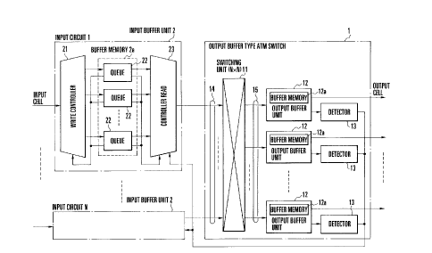
Fig. 1 shows the arrangement of a priority
control apparatus for cells in an output buffer type ATM
switch according to an embodiment of the present
invention. Referring to Fig. 1, reference numeral 1
denotes an output buffer type ATM switch which performs
switching on the basis of routing information (output
port number or the like) stored in an input cell and
outputs a cell in accordance with the transmission
capacity of an output side; and 2, a plurality of input
buffer units, respectively, arranged between a plurality
of circuits and the ATM switch 1, for performing
priority control on the basis of a loss quality class
and a delay quality class added to the input cell.
In the ATM switch 1, reference numeral 11
denotes a switching unit, comprising N input ports 14
and N output ports 15, for switching (self-switching) a
cell input from each input port 14 to a predetermined
output port 15 on the basis of routing information added
to the cell; 12, a plurality of output buffer units
connected to the output ports 15 and having buffer
memories 12a for storing cells output from the output
ports 15 depending on priorities and broadcast outputs
defined on the basis of the delay quality classes of the
cells; and 13, detectors, respectively, arranged for the
.~. _ ~I4~065
output buffer units 12, for outputting output buffer
threshold exceeding signals to the input buffer units 2
when the numbers of cells stored in the buffer memories
12a in the output buffer units 12 exceed a predetermined
threshold. Each buffer memory 12a may be constituted by
a plurality of memories to store cells depending on the
priorities and broadcast outputs of the cells.
In each input buffer unit 2, reference
numerals 22 denote a plurality of logical queues,
virtually set in a buffer memory 2a in accordance with
delay quality classes and the output port numbers of the
switching unit 11, for temporarily storing input cells;
21, a write controller for selectively writing the input
cells in the logical queues 22 on the basis of the cell
storage amounts of the logical queues 22, delay quality
classes added to the input cells, and the output port
numbers; 23, a read controller which reads the cells
from the logical queues 22 having a higher priority on
the basis of the cell storage amounts in the logical
queues 22 and the output buffer threshold exceeding
signals from the detectors 13 of the ATM switch 1 and
outputs the cells to the switching unit 11.
The buffer memory 2a is divided into a
plurality of first areas, e.g., each for a delay quality
class, and each first area is divided into a plurality
of second areas each for a output port number. The
logical queues 22 are respectively formed in the second
_ g _
__ _2148065
areas of each first area. Note that the relationship
between the delay quality classes and the first areas
can be replaced with the relationship between the output
port numbers and the second areas.
Fig. 2 explains a read priority based on delay
quality classes. A loss quality class and a delay
quality class added to an input cell are represented by
a priority class matrix CL(m, n). In this case, as the
loss quality class m added to an input cell becomes low,
the input cell loss easily occurs and has a high loss
rate. As the loss quality class m becomes high, the
cell loss does not easily occur and has a low loss rate.
An input cell whose delay quality class n is
low is not easily read out to prolong a delay time. An
input cell whose delay quality class n is high is easily
read out to shorten a delay time. In a read operation,
a cell whose delay quality class n is low has a lower
priority, and a cell whose delay quality class n is high
has a higher priority.
Fig. 3 explains the input buffer unit 2 in
Fig. 1 in detail. Referring to Fig. 3, reference
numerals 24 and 25 respectively denote logical queue
groups each constituted by the plurality of logical
queues 22 assigned to the same delay quality class.
Each of the logical queue groups 24 and 25 has the
logical queues 22 corresponding to the output port
numbers of the switching unit 11 and broadcast outputs.
_ g _
- 2148065
For example, the logical queue group 24 is constituted
by the logical queues 22 each having an initial delay
quality class n defined as n = 2, and the logical queue
group 25 is constituted by the logical queues 22 each
having an initial delay class n defined as n = 3.
Reference symbol V denotes a current cell storage amount
in each logical queue 22; Vm, a loss threshold for
determining loss of a cell; and Vn, a cell storage
threshold for determining transition of a delay quality
class.
A write process in the write controller 21
will be described below with reference to the flow chart
shown in Fig. 4. In response to reception of an input
cell, the write controller 21 loads routing information
such as an output port number and a priority class CL(m,
n) consisting of a loss quality class m and a delay
quality class n which are added to the input cell (step
S40). The logical queue 22 corresponding to the output
port number is selected in the logical queue groups 24
and 25 corresponding to the delay quality class (step
S41).
It is checked whether the area of the buffer
memory 2a in which the selected logical queue 22 is
formed has a free area (step S42). If the area of the
buffer memory 2a has a free area for storing the input
cell in step S42, the loss threshold Vm corresponding to
the loss quality class m loaded from the input cell is
- 10 -
2148065
referred to (step S43), and the current cell storage
amount V in the selected logical queue 22 is compared
with the loss threshold Vm (step S44). If the cell
storage amount V is smaller than the loss threshold V in
step 544, it is determined that the selected logical
queue 22 has a capacity which is large enough to write
the input cell in the logical queue 22, and the input
cell is written in the selected logical queue 22 (step
S45).
If all the areas of the buffer memory 2a in
which the selected logical queue 22 is formed are stored
with cells and have no free area in step 542, or if the
current cell storage amount V is equal to or larger than
the loss threshold Vm in step 544, the input cell loss
occurs (step S46).
In this manner, when the current cell storage
amount V of the logical queue 22 selected on the basis
of the priority class of the input cell and the routing
information exceeds the loss threshold Vm corresponding
to the loss quality class m of the input cell, the input
cell loss occurs. When the cell storage amount V is
equal to or smaller than the loss threshold Vm, the
input cell is written in the logical queue 22. For this
reason, loss control can be accurately performed for the
respective logical queues 22. A complex arrangement for
causing the loss of a temporarily written cell is not
required. For this reason, degradation of loss
- 11 -
2148065
characteristics caused by causing one logical queue 22
to consume a large amount of area of the buffer memory
2a can be prevented, thereby avoiding other logical
queues from being adversely affected.
A read process in the read controller 23 will
be described below with reference to a flow chart shown
in Fig. 5. In response to a predetermined cell read
timing, the read controller 23 performs a transition
process for the delay quality classes n of all the
logical queues 22 in the buffer memory 2a.
One of the logical queues 22 is selected in a
predetermined order (step S50), and it is checked
whether an output buffer threshold exceeding signal from
each detector 13 of the ATM switch 1 is output to this
logical queue 22 (step S51). If YES in step 551, the
delay quality class of the logical queues 22 is changed
into the lowest delay quality class (n = 1) representing
read inhibition (step S52).
Therefore, it can be confirmed that the
capacity of the buffer memory 12a of the output buffer
unit 12 corresponding to the selected logical queue 22
is small due to an increase in traffic or the like. The
cell is inhibited from being read from the logical queue
22 until the cell storage amount of the output buffer
unit 12 is decreased to disable the output buffer
threshold exceeding signal.
- 12 -
_2148065
If no output buffer threshold exceeding signal
is output to the selected logical queue 22 in step S51,
a cell storage threshold Vn based on a delay quality
class (initial delay quality class) preset in the
logical queue 22 is referred to (step S53), and the
current cell storage amount V of the selected logical
queue 22 is compared with the cell storage threshold Vn
(step S54).
If the current cell storage amount V exceeds
the cell storage threshold Vn in step 554, cells having
the number larger than a general cell storage amount are
stored in the selected logical queue 22. It is
determined that the cells must be preferentially read,
and the delay quality class n of the selected logical
queue 22 is changed into an upper delay quality class n
+ 1 (step S55). If the current cell storage amount V is
equal to or smaller than the cell storage threshold Vn
in step S54, only cells having the number smaller than
the general cell storage amount are stored. For this
reason, as it is determined that the cells need not be
preferentially read, the delay quality class n of the
logical queue 22 is changed into an initial class (step
S56).
As described above, the transition process
related to the delay quality class of the selected
logical queue 22 is finished on the basis of the cell
storage amount of the buffer memory 12a of the output
- 13 -
214806
buffer unit 12 and the cell storage amount of the
logical queues formed in the buffer memory 2a of the
input buffer unit 2, and this transition process is
performed for all the logical queues 22 (step S57).
Fig. 6 explains transition related to the
priority class of each logical queue 22. Reference
numerals 61 to 64 denote logical queues. Reference
symbols o denote the initial delay quality classes of
the logical queues 61 to 64; and ~, delay quality
classes which can be changed. That is, the symbols
denote the upper and lower limits of transition.
Referring to Fig. 6, for example, the initial
delay quality class n of the logical queue 62 is set to
be "3". When an output buffer threshold exceeding
signal is output to the logical queue 62, the delay
quality class n is changed into "1" which represents the
lowest delay quality class, and a cell is inhibited from
being read from the logical queue 62. Thereafter, the
delay quality class returns to "3" which represents an
initial delay quality class n.
When a current cell storage amount V of the
logical queue 62 is equal to or smaller than a cell
storage threshold Vm corresponding to the initial delay
quality class "3", the delay quality class of the
logical queue 62 is changed into the initial delay
quality class. When the cell storage amount V exceeds a
cell storage threshold Vm, the delay quality class n of
- 14 -
214806
the logical queue 62 is changed into a delay quality
class "4" having a level higher than the class "3" by
one level, and the priority for reading cells from the
logical queue 62 is set to be high.
In this case, although the delay quality class
n is changed into a class having a level higher than the
delay quality class n by one level, this transition
destination can satisfactorily correspond to maximum
traffic which can be instantaneously input from a user
(terminal) who selects and subscribes the priority class
of the transition destination, and the transition
destination is determined on the basis of a
predetermined correspondence limit offered as a service.
The transition amount is set depending on the interval
between delay quality classes.
Note that loss quality classes are not changed
even when these delay quality classes are changed.
Referring to FIG. 5, if the transition process
for all the logical queues 22 is finished in step 557,
of all the logical queues 22, the logical queue 22
having an uppermost delay quality class is selected.
It is checked whether the number of the logical queues
22 each having the uppermost delay quality class is one
(step S58). If the number of the logical queues 22 each
having the uppermost delay quality class is one in step
558, cells are read from the logical queue 22 and output
to the ATM switch 1 (step S60). If the plurality of
- 15 -
r. 2148065
logical queues 22 are selected in step S58, one logical
queue 22 is selected from the plurality of logical
queues 22 by a predetermined selecting method such as a
rotation priority method in which logical queues are
sequentially selected at equal intervals (step S59).
The cells are read from the selected logical queue 22
and output to the ATM switch 1 (step S60).
Therefore, the plurality of logical queues 22
are formed in the input buffer unit 2 in correspondence
with delay quality classes and output port numbers, and
an input cell is written in each logical queue 22 in
accordance with the priority class of the input cell and
routing information. The delay quality class of each of
all the logical queues is changed into an upper or lower
class in accordance with an increase/decrease in cell
storage amount V, and cells are read from the logical
queue 22 having the uppermost class. For this reason,
even if an excessive traffic is spontaneously input to a
logical queue having one priority class, cells are
preferentially read from the cell by changing the
priority class into an upper delay quality class.
Therefore, the method and apparatus for performing
priority control for cells can flexibly cope with a
change in traffic.
When the current cell storage amount V of the
logical queue 22 corresponding to the priority classes
of input cells exceeds the cell storage threshold Vn
- 16 -
214sos~
corresponding to the initial delay quality class of the
logical queue 22, the delay quality class n of the
logical queue 22 is changed into an upper class. When
the cell storage amount V is equal to and lower than the
cell storage threshold Vn, the delay quality class of
the logical queue 22 is changed into the initial delay
quality class. For this reason, transition control can
more accurately performed with respect to the respective
logical queues 22. In addition, when the lower quality
class of the logical queue 22 is changed into an upper
class, the delay time of the logical queue 22 originally
having an upper class is prolonged, and the upper class
of this logical queue 22 is changed into an upper class
having a level higher than that of the upper class of
the logical queue 22 originally having the upper class
in accordance with an increase in cell storage amount.
Therefore, original delay characteristics can be
obtained without being influenced by the transition of
the lower class.
Furthermore, the detector 13 for outputting an
output buffer threshold exceeding signal to the logical
queue 22 corresponding to the output port 15 of the
output buffer unit 12 when the number of cells stored in
the buffer memory in the output buffer unit 12 exceeds a
predetermined threshold is arranged, and the delay
quality class of the logical queue 22 to which the
output buffer threshold exceeding signal is output is
- 17 -
2148065
changed into a lowest read inhibition class. For this
reason, an excessive traffic is spontaneously input to
another line. When the free area of the buffer memory
in the corresponding output buffer unit 12 becomes
small, read access of cells from the input buffer unit 2
is temporarily stopped, and the logical queues 22 of
each input buffer unit 2 can flexibly cope with an
increase in the cell storage amount in the output buffer
unit 12. At the same time, when the delay quality
classes of the logical queues 22 are changed into read
inhibition classes, read access of cells from each input
buffer unit 2 can be controlled to be stopped without
any complex arrangement.
The write controller 21 causes an input cell
loss when the cell storage amount in the logical queue
22 selected in accordance with the input cell exceeds a
loss threshold corresponding to a loss quality class
added to the input cell. The write controller 21 writes
the input cell in the logical queue 22 when the cell
storage amount is equal to or smaller than the loss cell
threshold. For this reason, loss control can be
accurately performed for the respective logical queues
22, and a conventional complex arrangement for causing a
written cell loss is not required. In addition, unlike
in a conventional technique, degradation of loss
characteristics caused by causing one logical queue 22
to consume a large amount of area of the buffer memory
- 18 -
2148065
2a can be prevented, thereby avoiding other logical
queues from being adversely affected.
- 19 -