Language selection

Search

Patent 2148400 Summary

Third-party information liability

Some of the information on this Web page has been provided by external sources. The Government of Canada is not responsible for the accuracy, reliability or currency of the information supplied by external sources. Users wishing to rely upon this information should consult directly with the source of the information. Content provided by external sources is not subject to official languages, privacy and accessibility requirements.

Claims and Abstract availability

Any discrepancies in the text and image of the Claims and Abstract are due to differing posting times. Text of the Claims and Abstract are posted:

  • At the time the application is open to public inspection;
  • At the time of issue of the patent (grant).
(12) Patent: (11) CA 2148400
(54) English Title: SEALING GROMMET
(54) French Title: PASSE-CABLE D'ETANCHEITE
Status: Deemed expired
Bibliographic Data
(51) International Patent Classification (IPC):
  • A43C 5/00 (2006.01)
  • F16L 41/08 (2006.01)
(72) Inventors :
  • WRIGHT, JOHN O. (United States of America)
(73) Owners :
  • OSRAM SYLVANIA INC. (United States of America)
(71) Applicants :
  • OSRAM SYLVANIA INC. (United States of America)
(74) Agent: R. WILLIAM WRAY & ASSOCIATES
(74) Associate agent:
(45) Issued: 2001-04-03
(22) Filed Date: 1995-05-02
(41) Open to Public Inspection: 1995-11-06
Examination requested: 1998-01-05
Availability of licence: N/A
(25) Language of filing: English

Patent Cooperation Treaty (PCT): No

(30) Application Priority Data:
Application No. Country/Territory Date
8/238,287 United States of America 1994-05-05

Abstracts

English Abstract


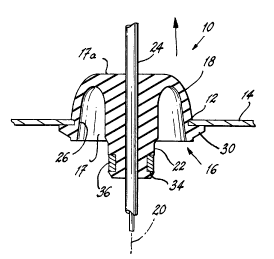
A sealing grommet for frictional fixation a wall comprises a substantially
campanulate body with a closed end and an open end. A central portion is clampedto a cable. a peripheral flange is provided on an outer surface of the body. Thehollow space existing between the internal surface of the open end and the central
portion collapses during insertion thereby greatly reducing the necessary seating
force.


Claims

Note: Claims are shown in the official language in which they were submitted.


The embodiments of the invention in which an exclusive
property or privilege is claimed are defined as follows:

1. A sealing grommet for frictional fixation in
a wall, said grommet comprising: a substantially
campanulate body with an open end and a closed end and
having a resilient outer portion having a given length
arrayed about a longitudinal axis; a central portion
arrayed about said axis, said central portion being
tubular and extending for a length greater than said given
length to provide an extended portion, said extended
portion being provided with a clamp receiving groove, and
a hollow space between said outer portion and said central
portion; a wall engaging groove formed adjacent a terminal
end of said outer portion; and at least one peripheral,
circumferential extending flange adjacent said groove.
2. The grommet of claim 1 wherein said extended
portion projects from and beyond said hollow space.
3. The grommet of claim 1 wherein said at least
one peripheral extending flange comprises two spaced apart
flanges.

Description

Note: Descriptions are shown in the official language in which they were submitted.


'~'->
93-2-347
PATENT
~a~~~er~..~~ao> >
SEALING GROMMET
TECHNICAL FIELD
This invention relates generally to grommets and more particularly to sealing
grommets. Still more particularly, it relates to sealing grommets for bringing
a radio
antenna cable through the fire wall of an automotive vehicle.
BACKGROUND ART
Prior art sealing grommets have comprised relatively massive, solid,
hemispherical
components of a flexible material, such as rubber. The component would be
provided with a groove for engaging the automotive vehicle fire wall and an
extending flange preventing pull-through. Such grommets frequently required a
setting force of up to 75 lbs. As the engine compartments of modern vehicles
becomes more and more crowded with electronic components, it becomes more
difficult to find the room necessary to be able to exert such pulling force.
DISCLOSURE OF THE INVENTION
It is, therefore, an object of this invention to obviate the disadvantages of
the prior
art.
It is another object of the invention to enhance sealing grommets.
It is yet another object of the invention to provide a sealing grommet with a
reduced
setting force.
These objects are accomplished, in one aspect of the invention, by a sealing
grommet which comprises a substantially campanulate body which has an outer
portion arrayed about a longitudinal axis. A central portion is also arrayed
about
the axis and is tubular. This arrangement defines a resilient hollow space
between
the outer portion and the central portion. A wall-engaging groove is provided
adjacent a terminal end of the outer portion and there is a peripheral,
extending
flange adjacent the groove.
Page 1

.. 21~~4~~
9~-i-3a~
~:::> PATENT
933478/APPL.v/OOt t
This construction allows the outer portion to collapse during insertion,
greatly
easing the task of fitting the grommet to the fire wall. No noticeable
decrease in
retention in the wall is present.
BRIEF DESCRIPTION OF THE DRAWINGS
Fig. 1 is an elevational, sectional view of an embodiment of the invention;
Fig. 2 is an elevational, sectional view of an alternate embodiment of the
invention;
and
Fig. 3 is a perspective view of the embodiment of Fig. 1.
BEST MODE FOR CARRYING OUT THE INVENTION
For a better understanding of the present invention, together with other and
further
objects, advantages and capabilities thereof, reference is made to the
following
disclosure and appended claims taken in conjunction with the above-described
drawings.
Referring now to the drawings with greater particularity, there is shown in
Fig. 1 a
sealing grommet 10 frictionally fitted into an aperture 12 of a fire wall 14.
Grommet
is substantially campanulate; i.e., it has a bell-shaped body 16 with an open
end
17 and a closed end 17a with an outer portion 18 arrayed about a longitudinal
axis
and is formed from a suitably resilient material. In a preferred embodiment of
the invention, the material is SAE R415K butyl rubber.
A central portion 22 also is arrayed about axis 20. The central portion 22 is
tubular
for engaging an antenna cable 24 and has a diameter smaller than the internal
diameter of the open end 17, thereby providing a hollow space therebetween.
Portion 22 diagrammatically corresponds to the clapper of a bell.
A wall engaging groove 26 is formed adjacent an open end 17 of body 16 and at
least one peripheral, extending flange 30 is positioned adjacent the groove
26.
Page 2


CA 02148400 2000-04-27
The body 16 extends along the axis 20 for a given length
and the central portion 22 extends along the axis 20 a
distance greater than the given length to provide an
extended portion which has a clamp receiving groove 34
formed therein. The extended portion 34 projects from and
beyond the hollow space.
An alternate embodiment is shown in Fig. 2 wherein an
additional extending flange 30a increases the pull-through
resistance of the grommet.
In use, the grommet 10 is positioned in a desired location
on cable 24 and fixed in that location by a clamp 36
installed in receiving groove 34. The cable 24 is then
inserted through the aperture 12 and pulled until the
grommet enters the aperture. Pulling direction is
indicated by the arrows in the figures. Pulling continues
until the grommet groove 26 seats around the edge of
aperture 12. The hollow space of the grommet collapses
during this operation to allow this seating to occur with
much less force than was necessitated by the solid
grommets of the past; however, the holding power of the
grommet of this invention matches that of the solid
grommets .
While there have been shown and described what are at
present considered to be the preferred embodiments of the
invention, it will be apparent to those skilled in the art
that various changes and modifications can be made herein
without departing from the scope of the invention as
defined by the appended claims.
-3-

Representative Drawing
A single figure which represents the drawing illustrating the invention.
Administrative Status

For a clearer understanding of the status of the application/patent presented on this page, the site Disclaimer , as well as the definitions for Patent , Administrative Status , Maintenance Fee  and Payment History  should be consulted.

Administrative Status

Title Date
Forecasted Issue Date 2001-04-03
(22) Filed 1995-05-02
(41) Open to Public Inspection 1995-11-06
Examination Requested 1998-01-05
(45) Issued 2001-04-03
Deemed Expired 2013-05-02

Abandonment History

There is no abandonment history.

Payment History

Fee Type Anniversary Year Due Date Amount Paid Paid Date
Application Fee $0.00 1995-05-02
Registration of a document - section 124 $0.00 1996-01-18
Maintenance Fee - Application - New Act 2 1997-05-02 $100.00 1997-05-01
Request for Examination $400.00 1998-01-05
Maintenance Fee - Application - New Act 3 1998-05-04 $100.00 1998-05-04
Maintenance Fee - Application - New Act 4 1999-05-03 $100.00 1999-05-03
Maintenance Fee - Application - New Act 5 2000-05-02 $150.00 2000-05-01
Final Fee $300.00 2001-01-02
Maintenance Fee - Patent - New Act 6 2001-05-02 $150.00 2001-04-19
Maintenance Fee - Patent - New Act 7 2002-05-02 $150.00 2002-04-19
Maintenance Fee - Patent - New Act 8 2003-05-02 $150.00 2003-04-22
Maintenance Fee - Patent - New Act 9 2004-05-03 $200.00 2004-04-21
Maintenance Fee - Patent - New Act 10 2005-05-02 $250.00 2005-04-20
Maintenance Fee - Patent - New Act 11 2006-05-02 $250.00 2006-04-13
Maintenance Fee - Patent - New Act 12 2007-05-02 $450.00 2007-09-13
Maintenance Fee - Patent - New Act 13 2008-05-02 $250.00 2008-04-17
Maintenance Fee - Patent - New Act 14 2009-05-04 $250.00 2009-04-20
Maintenance Fee - Patent - New Act 15 2010-05-03 $450.00 2010-04-13
Maintenance Fee - Patent - New Act 16 2011-05-02 $450.00 2011-04-14
Registration of a document - section 124 $100.00 2011-08-02
Owners on Record

Note: Records showing the ownership history in alphabetical order.

Current Owners on Record
OSRAM SYLVANIA INC.
Past Owners on Record
OSRAM SYLVANIA INC.
WRIGHT, JOHN O.
Past Owners that do not appear in the "Owners on Record" listing will appear in other documentation within the application.
Documents

To view selected files, please enter reCAPTCHA code :


To view images, click a link in the Document Description column. To download the documents, select one or more checkboxes in the first column and then click the "Download Selected in PDF format (Zip Archive)" or the "Download Selected as Single PDF" button.

List of published and non-published patent-specific documents on the CPD .

If you have any difficulty accessing content, you can call the Client Service Centre at 1-866-997-1936 or send them an e-mail at CIPO Client Service Centre.


Document
Description 
Date
(yyyy-mm-dd) 
Number of pages   Size of Image (KB) 
Description 2000-04-27 3 123
Claims 2000-04-27 1 32
Cover Page 2001-03-06 1 26
Claims 1995-11-06 2 37
Drawings 1995-11-06 2 34
Representative Drawing 2001-03-06 1 7
Cover Page 1996-06-28 1 13
Abstract 1995-11-06 1 13
Description 1995-11-06 3 121
Representative Drawing 1998-08-20 1 9
Prosecution-Amendment 1998-01-05 11 606
Correspondence 2001-05-24 2 63
Prosecution-Amendment 1999-11-01 2 4
Prosecution-Amendment 2000-04-27 4 137
Assignment 1995-05-02 5 199
Correspondence 2001-01-02 1 33
Fees 1999-05-03 1 37
Assignment 2011-08-02 2 91
Correspondence 2010-03-09 11 652
Correspondence 2010-05-18 6 411
Correspondence 2011-09-22 1 13
Fees 1997-05-01 1 83