Note: Descriptions are shown in the official language in which they were submitted.
2~48~19
, ,
IMPROVED DISC BRARE FRICTION PAD ASSEMBLY
FIELD OF THE INVENTION
This invention relates generally to automobile braking
systems, and particularly concerns an improved disc brake
friction pad assembly for utilization in such systems to generate
effective friction forces with reduced noise during system
braking operation.
BACRGROUND OF TNE lNv~l.,ION
The use of noise dampening material in combination with a
brake friction material and a metallic support element is well-
known as disclosed by U.S. Patent No. 4,240,530 issued in the
name of Tillenburg. Such patent teaches a disc brake friction
pad assembly comprised of a multi-part metallic carrier plate and
a friction material cure-bonded to one face of the carrier plate.
The carrier plate part joined to the friction material is bonded
to another similarly-configured carrier plate part by a cured
rubber-asbestos dampening material. Another publication,
Japanese Patent No. 62-106132 issued in the name of Kani to
Toyota, discloses the same type of brake friction pad assembly in
which the carrier plate parts are preferably made of a bainite
cast iron material. The elasticity (dampening material) layer
2148519
- 2 -
which joins the carrier plate parts together is unspecified by
the Japanese publication.
U.S. Patent No. 3,966,026 issued in the name of Filderman
teaches a braking member construction in which a noise reduction
capability is obtained through use of a friction material support
that is comprised of a stack of thin metallic sheets or strips,
contiguous to each other over their whole surface and all
assembled together by gluing, welding in zones, riveting,
insetting in a rim or flange, or the like. The nature of the
glue is not specified. See also U.S. Patent No. 4,064,975 issued
in the name of the same Filderman for another disclosure of the
braking member construction.
U.S. Patent No. 4,022,302 issued in the name of Janssen
teaches that brake noise reduction may be achieved by coating the
exterior surface of the brake support plate with a thin layer of
vulcanized latex.
A further teaching of a disc brake pad assembly utilizing a
noise dampening material in combination with a metallic support
plate (brake shoe) and a friction material is U.S. Patent No.
4,373,615 issued in the name of Melinat. In the Melinat assembly
a semi-metallic friction material is secured to a multi-part
metallic brake shoe comprised of bonded metallic, ceramic, and
elastomeric (rubber) layers.
U.S. Patent No. 5,083,643 issued in the name of Hummel et
al. and assigned to the assignee of this application, discloses
the use of a noise dampening material in the construction of a
drum brake friction block and shoe assembly. Such dampening
material is essentially an elastomer and is formed into separate
214~19
- 3 -
segments that are positioned in correspondingly configured
grooves located in the friction material block.
For a teaching of the use of an elastomeric sound dampening
material in a railway disc brake see Germany Patent No. DE
3734289-A. For a teaching of the use of a flexible graphite
sheet layer in a disc brake pad assembly which appears to
function more as a heat barrier rather than a noise reduction
device see Japan Patent No. 59-9326(A) issued in the name of
Maruya and assigned to Nissan.
SUMMARY OF THE l~v~.. ION
The disc brake friction pad assembly of the instant
invention is comprised of a friction pad element, a metallic
backing plate element, and a particularly-positioned, noise-
dampening shim subassembly comprised of an elastomeric material
lS lamina sandwiched between and bonded to spaced-apart metallic
laminae. It is important to the practice of this invention that
the shim subassembly be positioned intermediate the friction pad
elemen' and the backing plate element, so that the co-operating
braking system actuating piston will make direct contact with the
assembly metallic backing plate element during system operation
and not directly contact the noise-dampening shim subassembly.
Each of the metallic laminae of the shim subassembly preferably
are of considerably less thickness than the thickness of the
metallic backing plate member. The force applied by the system
actuating piston directly to the backing plate element is
` 2148~19
- 4 -
effectively distributed over the shim subassembly planform extent
to thus eliminate the presence of concentrated stresses in the
shim subassembly. The noise-dampening shim subassembly may be
incorporated into the disc brake friction pad assembly by either
integral molding, adhesive bonding, riveting, threaded fastening
or a combination of such procedures.
This invention obtains superior noise reduction in an
operating automotive braking system over the performance of any
of the known disc brake friction pad assemblies exemplified by
10 the prior art. Other advantages associated with this invention
will become apparent from consideration of the drawings and
detailed description which follow.
DE8CRIPTION OF THE DRAWING
Figure 1 is an orthogonal view of a preferred embodiment of
15 the disc brake friction pad assembly of the instant invention;
Figure 2 is an orthogonal view of the noise-dampening shim
subassembly which is incorporated into the disc brake friction
pad assembly of Figure l;
Figure 3 is a sectional view of the shim subassembly of
Figure 2 taken along line 3-3 of Figure 2;
Figure 4 is a sectional view of the shim subassembly of
Figure 2 taken along line 4-4 of Figure 2;
Figure 5 is a sectional view of the preferred disc brake
friction pad assembly of Figure 1 taken along line 5-5 of Figure
1;
214~51g
~_ - 5 -
Figure 6 is a sectional view of the preferred disc brake
friction pad assembly of Figure 1 taken along line 6-6 of Figure
l;
Figure 7 is an orthogonal view of an alternate embodiment of
the present invention incorporating the noise-dampening shim
subassembly of Figure 2 in a completely embedded condition;
Figure 8 is a sectional view of the alternate embodiment of
Figure 7 taken along line 8-8 of Figure 7; and
Figure 9 is a sectional view of the alternate embodiment of
Figure 7 taken along line 9-9 of Figure 7.
DETAILED DESCRIPTION
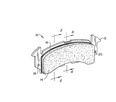
Figure 1 illustrates a preferred embodiment of the instant
invention. A disc brake friction pad assembly (10) is comprised
essentially of a metallic backing plate element (12), a friction
material pad or block element (14), and a noise-dampening shim
subassembly (16) positioned intermediate elements (12 and 14).
Backing plate element (12), sometimes referred to in the art as a
support element, a mounting plate, or a brake shoe element,
preferably is manufactured of a low-carbon steel and is provided
with a retaining means for structurally incorporating assembly
(10) into an automobile brake system - usually at each brake
system brake caliper assembly in the case of a disc brake system.
In backing plate element (12) the retaining means is a hole pair,
(18 and 20), which co-operates with correspondingly placed
mounting pins (not shown) provided in a brake system caliper
assembly.
21~8~g
-- 6
Friction pad (14) in the Figure 1 embodiment is comprised of
a molded, low heat-transfer, friction material. An example of a
satisfactory low heat-transfer friction material is a particulate
mixture with a formulation comprised of: approximately 12 weight
percent cashew nut shell particles or rubber particles, or a
combination thereof, approximately 12 weight percent straight
and/or modified two-step phenolic resin binder particles,
approximately 15 weight percent of carbonaceous material
(graphite, coke, carbon black), approximately 15 weight percent
fibers (Aramid, polyacrylonitrile and fiber glass), and 46 weight
percent minerals and fillers (magnesium oxide, silica,
rottenstone and barytes). All constituent ingredients of the
composition are thoroughly and uniformly mixed prior to use in
molding element (14).
Subassembly (16) illustrated in Figure 2 is a laminated
assembly comprised of an elastomeric material layer (34)
sandwiched between metallic laminae (30 and 32). Each of laminae
is preferably fabricated of a conventional high-carbon steel
material or other suitable metal. In thickness each of laminae
(30, 32) is significantly thinner than the thickness of backing
plate element (12). Elastomeric material layer (34) is a molded
component and provides a sound or noise-dampening capability in
assembly (10). Materials forming lamina (34) preferably are
noise dampening. These may include acrylic, nitrile rubber,
proprietary elastomeric layers (from Palmer International) or
viscoelastic materials.
21485~9
~_ - 7 -
Referring again to Figure 2, assembled subassembly (16)
components 30, 32, and 34 are each provided with registering
spaced-apart holes (22 through 28) adapted to receive friction
material of friction pad (14) to assist in securing pad (14) and
shim subassembly (16) to backing plate (12). It is important to
note that noise-dampening shim subassembly (16) in part also
functions as a thermal barrier to minimize the transfer of heat
during brake system braking operation from friction material (14)
which may have a semi-metallic composition to backing plate
element (12), especially to that region of element (12) which is
contacted by the face of the brake system caliper assembly
actuating piston (36) shown schematically (Figure 6). For this
reason it is important that the lateral separation of hole pair
(22, 24) from hole pair (26, 28) be greater than the diameter of
piston (36).
It is preferred that metallic laminae ~30 and 32) be bonded
to the faces of noise-dampening material layer (34) by a suitable
polymeric adhesive. Such a suitable adhesive may be either of
the two commercially-available synthetic rubber elastomeric
adhesives marketed in the United States under the trade names
"Cycle Weld" or "Plastilock" by B. F. Goodrich Company of Akron,
Ohio. It is preferred that the adhesive be applied as an evenly
distributed film over the faces of element (34) so as to have a
cured adhesive film thickness of from approximately 0.0003 inch
to approximately 0.0015 inch. After air-drying to remove
included solvents the adhesive films on the surfaces of lamina
(34) should be thermally cured by heating to a temperature in the
2148~19
__ - 8
range of 350 degrees Fahrenheit to 400 degrees Fahrenheit for a
period of from 3 hours to 1 hour, respectively. See also the
above cited U.S. Patent Nos. 4,240,530 and 5,083,643 issued in
the names of Tillenburg and Hummel et al., respectively, for
additional disclosures of adhesives suitabie for the practice of
this invention. Also, it should be noted that an elastomeric
adhesive film is preferably applied also to each exterior
metallic face of shim subassembly (16) before that component is
finally incorporated into assembly (10).
Base plate element (12), shim subassembly (16), and the
particulate friction material mixture which will comprise
friction pad element (14) are combined into an integrated
assembly (lOj using conventional mold apparatus preheated to a
temperature of approximately 320 degrees Fahrenheit. Base plate
element (12) is placed first at the bottom of the mold apparatus
compression cavity which has a cavity bottom planform basically
corresponding to the planform of base element (12). An insert
having an outer planform or configuration essentially
corresponding to the lateral extent of the mold apparatus and an
open interior with a planform corresponding to the configuration
of the exterior peripheral edge of shim subassembly (16) is
placed in the mold apparatus cavity upon base plate member (12).
Care should be taken that all of holes (22 through 28) in shim
subassembly (16) and base plate member (12) are in proper
registration.
The required amount of particulate mixture for forming
element (14~ with the necessary curing agents included, is then
placed into the mold apparatus cavity and evenly distributed over
2~4~19
,
g
the upper surface of shim subassembly (16) before mold apparatus
closure. Initially the particulate material is compressed by the
mold apparatus compression member by applying sufficient force to
develop an interior isostatic compression pressure of
approximately 2000 pounds per square inch throughout the
particulate mixture. The filled cavity interior should be vented
to the atmosphere for prescribed times to remove gases formed
following initial mold closure. Thereafter, the compression
forces are preferably increased to a level that will produce an
isostatic compression pressure of approximately 3000 to 5000
pounds per square inch in the compressed mixture and that level
of compression is preferably maintained for a period of at least
approximately 2 minutes or until the binder is fully cured and
the adhesives partially cured.
Lastly, the so-compressed and partially heated assembly (10)
is ejected from the mold apparatus and subsequently transferred
to a curing oven to be heat cured by raising the friction
material temperature linearly to approximately 350 degrees
Fahrenheit over a 3-hour time period and then maintaining the
20 heated assembly at the 350 degree Fahrenheit temperature for an
additional 4 hours of process time.
The embodiment of the invention disclosed in Figures 7
through 10 as disc brake friction pad assembly (40) differs from
assembly (10) of Figures 1 through 6 in several respect although
25 it does utilize the same backing plate member (12) and the same
noise-dampening shim subassembly (16) in its construction. The
basic difference is that the low heat-transfer friction material
21~8519
1 o
used for forming pad (14) of Figures 1 through 6 is replaced by a
composite material comprised of a semi-metallic friction material
facing (42) integrally bonded to a more extrudable backing
material portion designated (44).
An example of a typical semi-metallic friction material
satisfactory for use in forming element (42) of the Figure 7
embodiment friction pad is a particulate mixture having the
following formulation: approximately 5 parts barite particles,
approximately 1 part rubber particles, approximately 21 parts
carbonaceous particles, (coke, graphite, carbon), approximately
57 parts iron and steel particles (with at least 5% being steel
fibers), approximately 5 to 15 parts phenolic resin binder, the
remainder being fillers such as magnesium oxide, all constituent
parts being on a percentage parts by weight basis.
A typical extrudable backing material satisfactory for use
in forming element (44) of the Figure 7 embodiment friction pad
may comprise up to 40 parts of elastomeric material such as
latex, nitrile rubber or tire peels, 10 to 40 parts barite, 20 to
50 parts fibrous materials such as Aramid, glass fibers, steel
wool or wollastonite, and 10 to 25 parts resin particles, all
constituent parts being on a percentage parts by weight basis.
The preferred procedure for fabricating disc brake friction
pad assembly (40) generally parallels the procedure detailed
above regarding the fabrication of assembly embodiment (10). One
of the principal differences is that the mold apparatus cavity
insert has an open interior peripheral edge planform that is
uniformly larger than the planform of the periphery of shim
subassembly (16) so that upon completion of the molding operation
~148519
,
-- 11 --
the peripheral edge of the shim subassembly is completely
embedded in or surrounded by backing material (44). In addition,
the particulate materials for forming elements (42 and 44) of the
assembly friction pad component are placed in the mold apparatus
compression cavity in two stages. First the material (44) is put
into the mold cavity on and uniformly distributed over the upper
face of the properly positioned shim subassembly (16).
Afterwards, the required amount of friction material (42) is
uniformly distributed over the surface of the previously evenly
distributed composition (44). The mold apparatus is then closed
and the curing process may proceed as discussed above.
Disc brake friction pad assemblies (lO and 40) illustrated
in the drawings and described above each utilize a thermally
cured elastomeric adhesive applied to the exterior faces of
noise-dampening shim subassembly (16) to integrally bond such
subassembly to both the backing plate element and the assembly
friction material or noise-dampening backing material but other
means for securing subassembly (16) into the completed disc brake
friction pad assembly are contemplated. For instance, it is
possible to incorporate such subassembly into the completed
product by use of appropriately configured and located rivets or
threaded fasteners.
Other materials, component shapes, and component sizes than
those specified in the drawings and detailed description may be
utilized in the practice of this invention without departing from
the scope of the subsequent claims.