Note: Descriptions are shown in the official language in which they were submitted.
t.~~~~'.
~1~'~~OJ~
Wn 94/10944 - PCT/US93/09919 ':,.
APPARATUS AND METHOD FOR SPINAL FIXATION
f
f,:
DACKGROUND OF TfiE INVENTION M
Tlie present invention concerns an apparatus for spinal
osteo5ynthesis, applicable notably to degenerative or
misaligned vertebrae.
It is known that the vertebrae, in particular the lumbar ;
vertebrae, are subjected to a concentration of stresses, 1I1
which the discs and the ligaments play a significant
compensating part. If these vertebrae belong to a relatively
aged body, i:liey undergo a certain degeneration, which rnakes
the discs and the ligaments unable to completely fulfill
their role by reason of their aging.
These vertebrae then, are subjected to a certain
instability and tend to displace relative to adjacent
vertebrae. These displacements are uncontrolled and can be:
displacements in angulation and rotation, medio-lateral and
antero-posterior displacements, or else the combination of
these displacements.
It is therefore necessary to remedy this situation, which
risks generating a compression or compromise of the spinal
cord of the patient, by endeavoring to put the displaced or
misaligned vertebrae back to their positions.
. -, . . ~ : ' ..
.r,,s .
WO 94/10944 PC~TlUS93/09919 ''~.
~~~~~J~
-2-
I
_SUI'~MARY OF TI-iE INVENTION
The spinal osteosynthesis device, according to the
invention. comprises at least one longitudinal implant, suclu
as a rod, and by preference two, together with bone anchorage
elements joined to the rod, such as screws or hooks.
In accordance with the invention, this device comprises
at least one connection element between the rod and a
vertebra to be treated, and means for fixation of this
element to the vertebra, this element including a body, such
as a ring or collar, so dimensioned that the rod can he
mounted therein to move freely in rotation and in translatiocl
on the rod and outfitted with' means for fixing the ring on
the rod and extended radially by an arm, this arm and the
ring forming a one-piece unit.
In this way the terrninal ring of the connection element
can be mounted to be trapped on the osteosynthesis rod or
longitudinal implant, while being still free in trans1at10I1
anc3 in rotation before its fixation in the chosen position on
the osteosynthesis rod, by way of a suitable means for fixing.
According to one aspect of the invention, the means for
fixation of the connection element to the vertebra to be
treated is advantageously a bone anchorage element, such as a
screw or a hook of a known type, and whose body is open in a
U-shape in order to permit introduction into it of the free ;
end of the arm of the connection element. The invention
COIltemplateS that the anchorage element be free to both
translate medio-haterally along and rotate/angulate around
the extended radial arm of the connection element. This
aspect of the invention can be implemented with a hook having ,
a closed body with the longitudinal implant or rod extending
through an opening in the book body. , ',
In another aspect of the invention, the aforecnentioned
lateral connection element is used in a novel method for
correction of a spinal deformity. This method provides for
1~V~ 94/10944 _ ~ ~ ~~ ~ ~ ~ ~ PCf/US93/09919
t.
t
-3-
a
a
I
j
correction segmentally along the entire length of the~spine,
in all three degrees of Creedom and along the three columns
r
(posterior, middle and anterior) of the spine. Tlris method y
contemplates impiantirrg a strong yet ductile longitudinal
implant between several vertebrae. In one embodiment, t;he
implant is an osteosynthesis rod, although this method can )ae
applied using a bar or plate. The vertebrae are instrumented
with fixation elements, such as looks or screws, and the
fixation elernents are engaged to the longitudinal implant, or
rod. in a manner that permits free sliding translation and
rotation of tl.e fixation elements with respect to the rod.
In the preferred emuodiments, this engagement is effected by
the lateral connection element.
Unce the instrumentation is in position, tire spinal roc?
is contoured within the patient, or insitti, until the rod has
assumed the shape of a properly oriented spine. As the rod
is contoured insi.tu, the fixal:ion elements engaged to the
vertebrae irnpart corrective forces to the successive motion
segments. Since the fixation elements are free to translate
and rotate relative to the rod being contoured, the motion
segments are allowed to automatically and naturally seek
their proper anatomic position. This irtsitu contouring
approach involves manipulation of the motion segments so that.
the axes of movement of the segments is as near to the
neuroforamina as possible to avoid the risk of compromising
the neural canal.
An important feature of the invention that permits ''
application of the in~sittt contouring approach is the mal.erial
i
properties of the longitudinal implant. Tlre implant must ;
naturally be strong enough to withstand the often severe
loads imposed on it by the spine. The implant must also be
stiff enough to resist deformation under these loads once the
instrumentation is complete. At the same time, the implant
nrust Le formed of a material that is sufficiently ductile to
allow the implant to be deformed within the pai:ient and
°
of : ~. s ::,
P~'/US93/09919 ' ,.' . 2 :-
WO 94/10944 ~y i~~ ~,
-q_
substazrtialJ.y retain that imposed deformation. Given the t
narrow confines in the spinal region, it is undesirable to
"over contour" the implant with the expectation that tine
°'springLack" properties of the implant will decrease the
final deformation. Thus, the implant material preferably
exhibits an optimum ductility, or more particularly,
maintains in its final position a high percentage of the
imposed deformation.
Tn order to achieve this novel in situ contouring and r
correction, specially designed tools are provided. One tool,
a traction rotator, is configured to engage the ends of a
lateral connection element so as to provide a rotational
force to the element. In addition, the traction rotator can
have forked arms at its end to contact a body engaged to the
arm of the lateral connection element to apply a traction
force to that body. A second tool, a counter-rotator, is
configured to engage the .lateral connection element at a
lower vertebral level to hold this lower element fixed ~ntiile
a subsequent level is operated on by the traction rotator.
Beading irons are set forth in a further aspect of the
invention which are specially suited for manifesting this in
sittc contouring approach. A right angle or L-bender permits
bending the rod within the patient in the sagittal plane. A
rod grip bender proviQes a cylindrical surface for gripping
the rod as it is bent. This rod grip bender greatly reduces
the local deformation experienced by the rod as i:he bending
force is transmitted through the bender to the rod. '
'The present invention contemplates instrumentation over
several lumbar and thoracic vertebral levels. In addition, ~,.
another feature of the invention resides in intrasacral . ~y<-v .
fixation at the distal end of the longitudinal implant. In ',
accordance with one embodiment, the longitudinal implant, , -,
such as a rod. is extended into a bore formed inferiorly from
the L5-S1 junction. A sacral screw having an oblique canal
for receiving the rod is buried into the lateral sacral mass,
CA 02149036 2004-02-18
61211-1169
-5-
generally beneath the iliac crest. The iliac crest provides
a "buttressing" effect to resist pullout of the sacral screw
and to help alleviate the loads exerted on the screw and rod
at the LS-S1 junction by pelvic rotation and bending. This
"iliac buttress" combines with the proximal sacral screw and
the distal rod engagement within the sacrum to form a firm
and strong foundation for the longitudinal spinal
instrumentation.
In yet another aspect of the invention, the lateral
connection element can be used to position a plurality of
vertebral fixation elements at a single level. In one
embodiment, one lateral connection element is engaged to a
spinal rod, while another lateral connection element is
,engaged to the first. On vertebral fixation element is
engaged to the rod, while a second fixation element is
engaged to the second lateral connection element, Which can
extend substantially parallel to the principal rod. In this
manner, the first and second fixation elements can be
oriented laterally virtually side-by-side. For example. a
pedicle book and a supralaminar hook can be situated at the
same level. In another embodiment, a laminar hook can be
associated with a vertebral fixation screw, so that the hook
can strengthen the construct against screw~pullout.
It is one object of the present invention to provide a
spinal fixation system for the. correction of spinal
deformities that accommodates multiple, and even variable,
positions of a vertebral fixation element relative to a
longitudinal implant. Another object resides in a method for
correcting the spinal deformity that can be implemented with
fixation elements engaged at any one of many positions in the
vertebrae.
Some other details and benefits of the inventions will
appear in the course of the description which follows, taken
in reference to the,annexed drawings Which illustrate one
Preferred embodiment by virtue of non-limiting examples.
CA 02149036 2004-09-15
61211-1169
- 5a -
Thus in a broad aspect, the invention provides a
spinal osteosynthesis device applicable in particular to
degenerative vertebrae, comprising: at least one rod (1);
at least two bone anchorage elements (3, 15) interconnected
by the rod; and at least one connection element (4) for
connecting the rod (1) to one bone anchorage element
anchored to the vertebra (L2) to be treated, said connection
element including; a ring (8) which is so dimensioned that
the rod can be mounted therein to move freely in rotation
and translation; means (14) for fixing the ring on said rod;
and an arm (9) radially extending from said ring for
connection to said one bone anchorage element, said arm and
said ring constituting a unit in one piece wherein the bone
anchorage element (3) includes a U-shaped body (5) defining
a passage (10) adapted to receive said cylindrical arm (9)
extended therethrough permitting rotation and translation of
said U-shaped body about said arm.
In another aspect, the invention provides a
connection element (4) for connecting a spinal
osteosynthesis rod (1) to a fixation element (3) engaged to
a vertebra (L2) to be treated, comprising: an elongated arm
(9), the arm being adapted to support the fixation element
while permitting rotation and translation of the fixation
element about said arm; a ring (8) integrally carried at one
end of said arm, said ring sized to receive the spinal
osteosynthesis rod therethrough; and means (14) for fixing
said arm to the rod ( 1 ) .
In another aspect, the invention provides a spinal
fixation system for correction of spinal deformities,
comprising: a longitudinal member sized to extend between a
plurality of vertebrae along the length of the spinal
column; a plurality of bone anchorage elements, each
engaging a corresponding one of the plurality of vertebrae,
CA 02149036 2004-09-15
61211-11F~9
- 5b -
engaging a corresponding one of the plurality of vertebrae,
one of said bone anchorage elements defining a passage
therethrough; a lateral connection element disposed between
said one bone anchorage elements and said longitudinal
member, said connection element including; a body having
means for slidably engaging said body to said longitudinal
member so that said body is free to move in rotation about
and translation along the length of said longitudinal member
while remaining engaged therewith; and an elongated arm
integral with said body and extending outward therefrom away
from said longitudinal member when said body is engaged
thereon, said arm sized to be received within said passage
of said one bone anchorage element to move freely in
rotation and translation; and means associated with each of
said plurality of bone anchorage elements for fixing said
element on one of said longitudinal member or said arm of
said lateral connection element.
In another aspect, the invention provides use of a
spinal correction device for the manipulation of a spine to
correct spinal deformity, said spinal correction device
comprising: a longitudinal member adapted to be implanted
such that it extends between a plurality of vertebrae of the
spine; a plurality of bone anchorage elements; vertebra
engagement means for engaging each bone anchorage element to
one of said plurality of vertebrae; and a plurality of
element connection means for connecting each bone anchorage
element to the longitudinal member; wherein said
longitudinal member is bendable with the vertebrae connected
thereto.
In another aspect, the invention provides a spinal
fixation system for correction of spinal deformities,
comprising: an elongated rod sized to extend between a
plurality of vertebrae along a portion of the length of the
CA 02149036 2004-09-15
61211-1169
- 5c -
spinal column; a first bone anchorage element having a body
portion with means for mounting said body portion on said
elongated rod, and a portion configured to engage one of the
plurality of vertebrae; first and second connection
elements, each having a body defining an opening
therethrough and an arm integral with said body and
extending outward therefrom; and a second bone anchorage
element having a second body portion with means for mounting
said second body portion on said arm of said first
connection element, and a second portion configured to
engage said one of the plurality of vertebrae; wherein said
second connection element is engaged to said elongated rod
with said rod extending through said opening in said body of
said second element, and said first connection element is
engaged to said second connection element with said arm of
said second connection element extending through said
opening in said body of said first connection element.
,fvS.: r. ~.;_.a',~',.-
WO 94/10944 ,. ,l ~ ~ PCf/US93/09919
~~~~:~~ U
_6_
DESCRIPTION OF TF-!.); FIGUR1S_ I
FIG. 1 is a view in exploded partial perspective of one
preferred embodiment of a spinal osteosyntloesis device
including connection element according to the invention used
between an osteosynthesis rod and a bone anchorage screw.
FIG. 2 is a view from above in enlarged scale of the
connection ele«~ent depicted in the FIG. 1.
FIG. 3 is a view in perspective of a spinal
osteosynthesis instrumentation embodying one device according
to the invention, set in position on a spinal section in
which one of tl~e vertebrae is displaced to be returned into
alignment with the others. '
FIG. 4 is aai analogous view to FIG. 3 sliowi.ng a none
anchorage screw anc3 the corresponding vertebra in the course
of translation on the arm of the connection element according
to the invention.
FTG. 5 is an analogous view of FIG. 4 showing the
vertebra and the associated pedicle screw in their
definitive position, at the end of sliding an the arm of the
connection element and after rotation of the ring on the
principal rod.
FIGS. 6A-c are side schematic representations of a spinal
rnotion segrnent depicted in the sagittal plane and showing the
location of the axis of the segment during normal movement of
the spine.
FIGS. 7A-B are schematic representations of a motion
segment vieiued poste~riorly in the frontal plane and showing
the location of the axis of the segment as the spine moves.
FIGS. SA-B are schernatic representations of a motion
segment viewed inferiorly in the transverse plane and showing .
the location of the axis of the segment as the spine moves. , ,
FTGS. 9A-C are schematic representations of a motion
segment viewed in the sagittal plane in which the segment is
instrumented with a longitudinal implant that is contoured
: : .:~. ~:~;. .. ~; : . ;..
;~,:v
WO 94/10944 PC'1'/US93/09919
~
t~~~f~~~~ ;,.,
-7-
i
a
irt situ in accordance
wi th the princiF~les
of the present
,
invention.
I'IG. 10 is a graph of ductility for Clue material of t1e
longitudinal imp lant used in the i~tsittt contouring technique.
FIGS. 11A-B are perspective views of a spinal segment in
wlicl~ one vertebra is displaced and then subseguently
manipulated into its proper anatomic position.
rIGS. 12A-B are top and side elevational views of an
L-bender for use in i.at situ contouring of a longitudinal
irr~Plant.
FIGS. 13A-B are side and top elevational views of an rod
grip bender for use in insittc contouring of a longitudinal
implant.
FIGS. 14A-B are top and side elevational views of a
traction rotator tool for use in direct derotati.on of spinal
instrumentation iai accordance with the present invention.
FIGS. 15A-B are side and top elevational views of a
counter-rotator tool for use in direct denotation of spinal
instrumentation.
16 is a top elevatianal view of a lateral connection
FIG
.
element modified for use with the tools shown in FIGS. 14-15.
FIGS. 17A-B are anterior views in the frontal plane of
three vertebrae in which one displaced vertebra is restored
to its proper atomic position by direct denotation.
an
FIGS. 18A-B show in the sagittal plane the direct
denotation depic ted in FIGS. 17A-B.
FIGS. 19A-B show in the transverse plane the direct
denotation depic ted~in FIGS.17-18.
FIGS. 20A-B are side elevational and tap perspective
views showing
the sacral fixation
techniques and
"iliac ;r:-
buttress" of the present invention.
FIGS. 21A-B are side and top elevational views of spinal
instrumentai:ion using the multiple lateral connection
elements to permit
multiple single
level instrumentation
of a
vertebra.
~:~'y, ,:'i':~
WO 94/10944 ~ PCT/US93/09919 '''~v'
_8_
h)JSCR1PTION OF'' T11E PREFERRED EMBODIMENTS
For the purposes of promoting an understanding of t1e
principles of tree invention, reference will now he made to
the embodicnent illustrated in the drawings and specific
language will Le used to describe the same. Tt will
nevertheless be understood that no limitation of the scope of
the invention is thereby intended, such alterations and
furtler modifications in the illustrated device, an d such
further applications of the principles of the invention as
illustrated therein being contemplated as would normally
occur to one skilled'in the art to wlnich the invention
relates. '
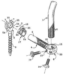
One sees in FIGS. 1 and 2 an osteosynthesis rod 1 of
wluich the surface presents a multiplicity of asperities 2,
for example forming the points of a diamond, a bone anchorage
pedicle screw 3 and a connection element 4 between the rod 1
and the screw 3 positioned laterally or medially to the rod 1
in a pedicle.
Tlse pedicle screw 3 is constituted by an open and
U-slyaped body 5 and by a threaded section 6, which is of the
type of the one described in t1e >rrench patent 89 09 925 (2
95 732) in the name of Yves Cotrel. The screw is normally
adapted to receive, between the branches 5a of body 5, a rod
1 with asperities. Threaded apertures 7 are defined in the
branches 5a to receive screws 19 (FIGS. 4-5) provided for
fixing on the rod, this fixation being completed by a
cylinQrical clamping'meinber l~7 closing channel 10 of body 5.
Clamping member 17 is so dimensioned to be introduced a.n v
the U-shaped body 5 with a.rm 9 extending tlierethrough. IL .
ic~cludes a central screw 18 capable of being screwed into a
threaded aperture in a radial boss 23 dimensioned to slide .
between the ends of the brancles 5a. Clamping member 17 is
moreover pierced by apertures 22 for passage of the lateral
screws 19, and is provided with a collar 24 forming a
_:::..
WO 94/10944 ~ 1 ~ ~ ~ ~ ~ P~1'/US93/09919
f.
-q_ ~
i
shoulder adapted for support on a corresponding face 25
defined on an entrance edge of channel 10 of body 5. '
The element 4 includes a body, such as ring 8,
dimensioned to be able to receive principal rod 1 extended
therethrough, and an arm 9, preferably cylindrical and of a
diameter substantially equal to the one of the channel lU,
extending radially from ring 8 to a suitable length, and
forming a one-piece unit with the ring. The arm 9 is adapted
to be able to penetrate an d slide in cylindrical channel 10.
lts surface preferably presents a multiplicity of asperities
11 (FIG. 2), which could be similar to asperities 2 on rod
1. The surface of the arm with asperities 11 is joined to
ring 8 by a smooth section 12 of diameter slightly smaller
tlzau the one of the portion with asperities.
Apertures 13. numbering four in the represented example
'although other nurnbers are possible), are radially disposed
in ring 8. so that one pair of apertures is symmetrical to
the other pair with respect to diameter XX of ring 8, which
intersects the axis of arm 9. These apertures 13 can receive
corresponding screws 14 for clamping the element 4 against
translation and rotai:iorz on rod 1 in the chosen position.
The solidity of this fixation is increased by asperities 2
which afford a connection of very high mechanical quality.
Pedicle screw 3 constitutes a means of fixation of arm ~ ,
of eleznent 4 in the degenerative vertebra to be treated. In
order to do this, arm 9 is introduced in U-shaped body 5 and '
blocked by the aforementioned means 7, 17. 18 and 19.
Clamping znemlier 17 closes t>~ze~ aperture of the U in body 5
assuring the security of t;he mounting. Indeed. in the event
1..
of the breakage of lateral screw 19. arm 9 cannot, due to the =-v
fixing of member 17, become detached from the body 5 of the
screw 3.
Tloe ring 8 cart be mounted free in translation and in
rotation on the pri.ncapal rod 1 and can then be locked ozz
~':; :. . , : ': '. ~ . :. ~ . ; ,~ ,
WO 94/1U944 :~ ~ (~ ~ Q ~~ ~d PCf/US93/09919 ~::.;::'-
-10-
the rod Lay the radial means constituted by screws 14.~
Alternal:ively, tlne means for fixation of arm 9 on tire
vertevra to ve treated can Le formed key a threaded plug,
according with th a teaching of the French patent 2,33,177
(88 08538) or by a system similar to that disclosed in the
French patent 2,545,350 (83 07450). Tlie asperities on arm
the 9 and on the rod 1 are preferably formed, but not
necessarily, according to the French patent 2,545,350
(83.0745U). (These asperities constitute the means for
anchorage of the extremities of screws 14, 18 and 19.)
Tle osteosynthesis instrumentation illustrated in I~'IGS. 3
to 5 includes two straight rods 1, lA extending the length of
three vertebrae, for example L3, L2, L1, and joined by known
transverse connection devices 21. (These devices 21 and the
rod lA are represented in phantom in FIG. 5.) Tine
intermediate vertebra L2 is shifted with relationship to the
others and must therefore be restored to its desired position
by positioning the instrumentation.
The osteosynthesis device according to the invention is
placed lrl position by the surgeon in the following manner.
The osteosynthesis rods 1 and 7.A are firmly set in two
points of anchorage to vertebrae adjacent lumbar vertebra
L2. The two anchorage points of rod 1 are then accomplished
on tlne adjacent vertebrae Ll and L3, by screws such as 15
(FIG. 3). of a known type. The surgeon completes the
mounting with the transverse connection devices 21 jointing '
rods 1 and lA (FIG. 5).
The rocl is intended to serve as tire support fur lateral
connection element 4, which is previously loosely joined to
e'
,'
i.t by axial introduction of ring a on rod 1. The ring 8
becoraes trapped Uut is free in rotation and in translation,
in tire free space separating fixation screws 15 from , '.
osteosyrathesis rod 1.
Tlre means for fixation of element 4 to the degenerative
~':7a': .'.
.:
WO 94/10944 ~ ~ ~~' ~ ~' '~ ~ PCT/US93/09919 ~:'.':e.:'
. ~;:
-11- i
vertebra L2 to be treated, for example a pedicle screw 3, is
fixed Lo this vertebra L2. The free end of arm 9 can then be
easily introduced in channel 10 of U-shaped body 5, and can
stay free in translation and rotation. The action of the
surgeon consists then, with the assistance of suitable tools,
to reposition the vertebra L2 with relationship to the
adjacent vertebrae L1 and L3, to its original position. To
do this, the surgeon manipulates body 5 of the screw 3. Tluis
leaving been done, the rotational position of ring 8 in
relationship to osteosynthesis rod 1 is automatically
modified, and in this way too the position of body 5 of tree
pedicular screw 3 along the length of the lateral connection
arm 9.
As soon as the surgeon decides that the given vertebra L2
is in the desired position with relationship to the adjacent
vertebrae Ll and L3, the surgeon tightens the connections by
first the anchorage screws 14, on rod 1, then screws 18, 19
on arm 9, in order to achieve:
on one hand the fixation in rotati0I1 Of ring 8 on the
osteosynthesis rod 1
- - on the other hand, the fixation in translation and
rotation of body 5 of screw 3 on lateral arm 9.
The position of the vertebra L2 to be treated is then
firmly maintained mechanically lay instrumentation. Of course ,
the second osteosynthesis rod lA of the instrumentation does
nut need to be likewise provided with a lateral connection
v
element 4., < ; , ,
TPre presence of asperities on the whole surface of tle
rod 1 and the arm 9 allows a quality anchorage of the '
blockage screws 14, 18 and 19 to be obtained on all points of
r
displacement. These screws act radially on rod 1 and arm 9
by exerting a strong pressure, thereby assuring a favorable !,
connection in rotation and translation.
Connection elerrient 4 according to the invention enables
the surgeon to link.a rod 1 of an osteosynthesis
-s~~-'~. .~ r . ' .. . ... ,
~..:' ~ ...:: , , .. ~ . -:: (,.,.,.. '.:.. .... ~., ,:. ,, ,..~ .. . ., , ,
'.....
..:. ~..~,:r- . .. .,..~ ... :.:~..~~ =,...... . . :.'~.. . , -.: . .:. , ~
':. ~ -'.;~~'' . ~ ~:'~" ~. ~. ., ' . ... . , ~ ~ ; . ~ ..
~~.,,,~,; , :: 4:
WO 94/10944 PCT/US93/09919
~. ~,~ ~~(~ ~~'~3 t3 -12-
irrstrramentation of the COTItEL-DUHOUSSET type to a pedicle
screw or to a sacral screw, leaving it with carnplete freedom
in flue respective position of the two respective axes of tire
rod an~.l screw (angles acrd distance). Indeed this system
permits a rotation of the vertebra in the horizontal or
transverse plane, while letting this vertebra place itself
angularly irr the sagittal plane without incurring
interference constraints, thanks to the degrees of freedom
allowed by the mounting. Using two connection elements
together provides even greater degrees of freedom lry the
mountings.
1'lie invention is not limited to the preferred embodiment
described, acrd can include several variants of its
implementation.
'Thus, instead of being completely closed as represented
in the drawing, the ring can be opened or presenting a slot
(FIG. 1). The blockage or fixation element such as screws
14 (the number of which can evidently vary while being at
leash one), then extend through the ring on each side of slot
20 20. Likewise, anchorage screw 3 can be substituted by a
screw similar to tlne one represented in FIG. 4 of French
patent 2, 645, 732 (89 04 926) , craving lateral branches of
unequal lengths which define a lateral aperture, and no
longer a rear opening, for the introduction Of arrn 9.
Clamping member 17 is them obviously modified to accommodate ;
this asywmetrical body. This last type of screw brings a
supplementary security ,in the maintenance of arm 9. Clamping 3w
member l7 can likewise be replaced by one of the fixing ,
elernents described in French patent 2,645,732.
i ~:
F'
Tlie pedicle screw linked to the degenerative vertebra can
likewise be a closed head screw. It can also be replaced by .
i
a spinal hook provided with a channel for receiving , ;
connection element 4. This channel could be, like the screw,
closed or else upwardly open, and presenting a similar
U-shape. The U-shaped head. of the hook or the screw, could
. ., ,: ; _. , ; :. " . , : . ~ ~ :. .
:,. .. ..... ., .. ... .' ,:. . , . , ' , . .
W0 94/10944 ~ J .~ ~ ~~ y''l PCT/US93/09919 ~:~> ~:
~ ~_ .
~.
-1.3-
be closed by a threaded plug such as described in French
patent 2,633,177 (88 08 538) of 29 June 1988 filed by Yves
r
Cotrel. '
Finally, apertures 13 defined in ring 8 can be in rrurnber
more or less than those described previously in tha preferred
ernbodirnent. Advantageously, they can be arranged on the ring
so that, whatever the rotation of ring 8 on rod 2 is during
the repositlonlng of the degenerative vertebra vy the
surgeon, one or several apertures are easily accessible to
introduce there a clamping screw on rod 2.
As alms far described, the novel connection element 4
provides rneans for varying the orientation of the fixation
screw, such as screw 5, relative to the primary rod, or rod
1. As explained above, manipulation of the displaced
vertebra causes the connection element 4 to rotate arrd its
engagement with the screw 5 to translate along the length of
tire arm 9 until the vertebra is in its proper position. At
that tirne, tire several clamping screws can be tightened to
form a rigid construct.
Tlye connection element 4 has been found to be important
in another method for fixation of tire spine and correction oC
spinal deformities. In this alternative method, rather than
manipulating the vertebra itself into position, the
instrutnerrtation is. manipulated to adjust tire positron Uf the
displaced vertebra. In this instance, then, the ~ixation or ,
anchorage elernent 3 translates a corrective force to the
vertebra, rather than as in the previously described method '
in which the vertebra (:ransrnits a displacement force to the
components of tire connection element.
In order to facilitate an understanding of this novel
method, it is first valuable to understand the b:iomechanics
of the spine and its motion segments, as developed by the
~.
present inventor. The term "motion segment" as used herein
constitutes adjacent vertebrae and tire disc therehetween.
First with reference to FIG. 6A, it can be seen that the
... I,., ; ,,. : ; ;. . . ..
y: ., . ~ ; ,
...Y,.~~,: .
f'a.,
WO 94/10944 PCT/US93/09919 w ,
-14-
spine can be divided into three columns along i.ts length - ;
the auteriar, middle and posterior columns. The inventor lras
found that correction of spinal deformities requires
consideration of correci:ion in each of these three columns.
F'rior art techniques for correcting spinal deformities
have tended to focus simply upon one of the three colurnns,
usually the posterior column. ror example, tire original
Harrington systecn contemplated compression or distraction
using posteriar instrumentation. 'thus, tree Harrington
1G instrumentation achieves compression or distraction of the
posterior column of the spine, without specific consideration
of the impact to the spine in the remaining two columns. In
subsequent segmental systems that implement anchorage
elements at eactn vertebral level, again the corrective forces
are applied typically in but a single one of the columns,
which may lead to difficulties in the other of the columns of
the .spine.
In otluer systems, tare spine is translated to a rigid
rorl. Lxamples of this approach can be found in tire Luque
Wiring System, sold by Danek Medical, Inc., and the Isola
System of AcroMed Corp. These systems provide little control
of transverse rotation of the motion segments. A third
approach involves engaging a pre--contoured rod to the spine
and then rolling the rod to tluereby alleviate au abnormal
scoliotic curvature. This approach again provided little ,
control over transverse rotation.
Understanding of this new method also requires
consideration of tlre~ spinal motion segments, o~r the tire
relative movement between two adjacent vertebrae and their ;.
connecting disk. Proper correction of spinal deformities
requires consideration of the biomechanics of the motion
segment at each level acrd particularly requires awareness of . '.
how tire axes of motion of the segment moves as the segment is
subjected to bending, tilting, angulation and rotation. As
will be more apparent from FIGS. 6, 7, 8, tire axes of tire
.., ..., , . . , . . . . ;. , .;,
,;...
' WO 94/117944 ~ ~ ~~ ~ ~ J i~ PCT/US93/09919
-15-
rnotion segments both rotate and translate. Failure tq
r
consider both types of notion may yield inferior correction
arid may lead to other curnplications. AccomrnodaLing tlue
rotation and translation of the motion segment axes is
important to permit separate control of each of the three
columns of the spine as well as correction in each of the
three planes .
Prior apgroackres do not account for the complicated
biorneclxanics of the spine. vistraction or compression in
Prior rod systems utilizing pre-contoured rods tend to place
the angle of angulation of the spinal segment far remaved
from the true axis of the motion segment. Typically, this
axis of angulation in prior'systems is in t1e pedicle into
which tire screw is inserted and not at the level of the disc,
deformity or injury. As can be seem from the following
discussion, this approach is contrary to the normal
biomecinanics of the spine.
Referring first to FIGS. 6A - 6C, a spinal motion segment
is depicted in the sagittal plane. In FIG. 6A, tle neutral
Position of the motion segment is shown in which the axis A
is located in the middle column and posteriorly and
inferiorly in the disk. In l:lre sagittal plane, the motion
segment is subject to angulation in which the adjacent
vertebrae rotate relative to each other. In the case of
flexion, as sluown in FIG. 613, thre axis A moves anteriorly and w
superiorly into the center of the disk. On the other band,
in extension, as shown in FIG. 6C, the axis moves posteriorly
and inferiorly slightly below ttie inferior endplate of the ,
disk: It is trxus apparent that the axis of each spinal
x. .
motion segment translates with angulation in the sagittal
plane.
'fhe same pluenomenon is exhibited in tire f routal plane, as ' ,
shown in FIGS. 7A and 7F3. In FIG. 7A, the neutral position
of the axis A is along Lhie midline of the spine and somewhat
below the center of tlxe disk close to the inferior endplate.
. , ., ... .:: : w., ;. . ,
~~~s
«'O 94/10944 . YCT/US93/09919
~~~~~J~ -16-
1
Witlr the interior vertebra held stationary, tyre superior
' vertebra can bend laterally, or tilt, to the right or to the
left. A tilt to the right is depicted in FIG. 7B, in which
it is seen drat tire axis A moves not only laterally to the
left but also somewhat cephalad into the disk. A tilt to the
left would product an opposite lateral movement of tire axis
with a similar cephalad movement. Again, the axis of the
motion segment translates in the frontal plane,
f'irrally, the vertebrae appear in the transverse plane in
FIGS. F3A and SB. In the neutral position shown in FIG. 8A,
tire axis A is disposed generally in the centroid of-the
neural canal C. With rotation to the right or left, the axis
A always remains within the'neural canal, as shown in FIG. nF~
for rotation to the right. The axis does shift laterally
somewhat in a direction opposite to the rotation, but
nevertheless always remains within the canal. This i: an
irnportant aspect of proper motion of a spinal motion segrnezrt
since maintaining the axis of the motion segment within the
neural canal is protective of all of the neural elements
passing l.herethrougla. It is believed that many prior systems
and techniques for correcti0ll of spinal deformities have a
tendency to displace the axis out of the canal leading to an
increased risk of damage to tire neural elements . I t caai be
seen from this view in the transverse plane brat the
vertebral motion segment has a very narrow window of movement
before the axis of tyre segment leaves the canal C. Any
correction applied to the spine that does not take into
account the aspects,of rotation in the transverse plane bf a
y.
motion segrnent carries the risk of damaging the neural
elements Izoused within the canal.
Frorn the foregoing FIGS. 6-8, it cart be seen that every
segmental spinal motion segment involves bath translation and ',
rotation in each of the tluree planes (sagittal, frontal and v
transverse). Thus, in the frontal plane, the motion segment
Can translate up and down and left to right, and can rotate
WO 94/10944 ~ ~ ~ ~ ~ ~ ~ PCT/US93/09919 ~ _..:'
-17-
or tilt left or right. In the sagittal plane, the sec~,merrt
can translate up and down and posteriorly and anteriorly,
wluile it can rotate, or more particularly angulate, in 1
flexion or extension. Finally, in the transverse plane, the
motion segment biomechanics yields translation to the right
or left, or anteriorly or posteriorly, and rotation to either
the right or left, again always maintaining the axis within
the neural canal.
With this explanation of the movement of the spinal
motion segments, it can be appreciated that optimum
correction of spinal deformities should permit the motion
segments to move in the manner for which they were designecJ.
In relation to tyre three spinal columns discussed above, it
is also important to control the correction of the deformity
by keeping the motion segment axes between the longitudinal
implant, or rocl, and tyre middle spinal column, or close to
the .neural canal. Witlr the present tectmique, it is possible
to achieve elongation or distraction of the anterior and
middle columns anterior to the motion segment axis, and
approximation or compression of the posterior column behinQ
the axis. In accordance with the present invention, tire
surgeon, and not the instrumentation, determines the location
of the motion segment axes.
A further feature of the invention provides tire means for
achieving this optimum segmental and global correction of Clue
spice. More particularly, the invention contemplates in situ
contouring of a longitudinal spinal implant when it is
engaged to several vertebral bodies by screws or hooks.
While the longitudinal implant may be a plate or bar, i:he
preser:t ernbodiment contemplates the use of a spinal rod, such
as previously described. Contouring the rod alone is not
sufficient arid will frustrate the normal movement of the
three columns of the spine and the spinal motion segments.
Specifically, insitu contouring of a rod rigidly engaged to
the spine will simply translate the vertebrae without
nF~:r'~,. .=ty;<.~.
i:...i...v.::. .:.7..:.:.....
WO 94/10944 PCT/US93I09919
-18-
considering the needs of the motion segment axes explained
previously.
Tlzus, a further aspect resides in connecting the
vertebral fixation elements, such as bone screw 3, to the
rod, such as rod 1, in a manner that permits free rotation
and tz-anslation of the vertebra to which the bone screw is
attached relative to the rod as it is being contoured. This
capability is achieved by the collar or ring 8 engaged to the
rod 1, as well as the cylindrical fixing element 17 engaged
to the arm 9 of the ring 8. As previously describeQ, each of
these components is free to translate and rotate relative to
the component to which they are engaged. In this manner, as
the rod is contoured, corrective forces are applied to the
vertebral segment while tree free degrees of rotation and
translation permit l.lze vertebra to seek its proper
biomechanical orientation. In addition, this agproach
accommodates the needed and necessary translational and
rotational degrees of freedom in each of the three planes of
a spinal motion segment.
3'his inventive approach to instrumentation of the spine
and correction of spinal deformities can be readily
understood from a few diagrammatic representations.
Referring first to the examples in FIGS. 9A-9C, in situ
contouring of the rod in tine sagittal plane is depicted. It
is understood that the system can be generally constructed as .
illustrated in FIG. 3, such as by implementing a rod 1
engaged to the vertebrae by way of a bone screw assembly 15.
Tlie construct in FIG,. 9A represents the uncorrected posiE'iau
of a spinal motion segment. In this position, the bone screw
assemblies 15 are displaced from each other by a distance
dl, In this arrangecnent, the axis A of the motion segment
is located in the middle of the disk D, similar to the
position illustrated in FIG. 6B. In order to restore the
segment to its proger position or alignment, and in order t;o
exert a proper and precise biomechanical force for this
>_ !w ' '..:.
WO 94/10944 ~ ~ '~. f~ ~ ~ ;,~ PCT/US93/09919
r
t
i
-19-
a
correction, it is necessary that the axis P along which the
corrective force is applied be able to translate in the
anterior/posterior directiorr. '
This neutral position is shown irz rIG. 9B which shows the
spinal rnotion segment after application of a bending force to
the rod 1. frzis bending force is applied between the two
bone screw assenrlalies 15 so that the rod 1 is essentially
bent around pivot point P, with the ends of the rod moving in
the direction of the arrows 30. In order that the axis A be
permitted to translate, it is ner_essary that the bone screw
assemblies 15 be able to slide along the rod 1 in the
direction indicated by the arrows 31. Permitting this free
translation of the screw assemUlies 15 along the rod 1 al7.ows
the azzter:ior disk space to opezz or elongate in the direction
of the arrows 32. Some compression of the posterior disk
space may also occur. In this instance, contouring the rod 1
while permitting sliding rnovement of the screw assemblies 15
beads to a decrease in the distance between the screws, as
represented by the distance d2, which is less than their
original uncorrected distance dl. Tt can further be seen
that the axis A is now situated in its proper neutral
position as shown in earlier I°IG. GA.
Z'he i~t situ contouring principles according to this
invention also contemplate contouring the rod 1 with the
screw assemblies 15 ~ixed to the rod, as shown in FIG. 9C.
In this instance, the distance measured along the rod between
the two screw assemblies 15 remains constant as distance
dl. f:ontouring the rod 1 about the pivot point P not only
produces distraction at the anterior part of the disk, as
~:
represented by arrows 32, but also distraction at the
posterior part of the disk as represented by arrows 33. 'flzis
i
procedure may be irnportaut to open up the disk space, suclo as
to decompress the disk D.
It.is also contemplated that both steps 9L3 and 9C can be
implemented to riot only t0 COIrtrol the axis A relative to its
~ :r' i4:~::;y.
WO 94/10944 ~ ~~ ~ ~ PCT/LJS93/09919 .,
:....,.
-20-
proper neutral position, but also to open up the ~ ,
neuroforamina as required. 'Therefore, the rod 1 can be
contoured slightly with the screws 15 free to translate along '
the rou. Subsequently, t;he screw assemblies 15 can be fixed
to the rod and further contouring of the rod 1 be
accomplished to open i~p Llie neuroforamina. It is understood
that with any spinal instrumentation, it is important that
the neuroforamina remain open to avoid trauma to the spinal
cord. In the preferred procedure to address this concern,
the screw assemblies are alternately locked and released on
the rod, and the rod contoured with each type of fixation to
achieve an "averaged axis" in the sagittal plane with respect
to the bending axis P. By this it is meant that the axis P
at which the contouring force is applied is maintained as
close to the neural canal as possible to avoid compromise to
the neuroforarnina. Typically, the "averaged axis" will
reside posterior to the disc and anterior to the longitudinal
implant or rod. Under ideal circumstances, the longitudinal
implant or rod would extend along the length of the spine
through the neural canal. Since this is naturally not
pbssible, the present insittt contouring principles allow the
"averaged axis" of the rod to be manipulated as close to the
neuroforamina as possible.
With this example, many beneficial aspects of this
inventive method can be discerned. It should first be
pointed out that this insitu contouring approach can be
implemented with any longitudinal implant, sucYi as rod, bar
or plate. Optimum application of the irasittc contouring
technique requires treat the osteosynthesis implant, such a~
rod 1, ~e a stiff, strong and ductile one. Tries reference to
a stiff strong ductile implant encompasses many mechanical
properties. It is important that the implant be able to be .
bent without elastically springing back completely or
partially to its original position. Thus, while the rod 1
must be ductile enough to be bent in situ, it must he stiff
:;.. ;, , , ; , . : . _ -:
. . . ~ . . , . ,, ,
;i :~;:1' ~::!.:
1~V0 94/10944 ~ ~ ~ ~ ~ J ~ PCT/US93/09919
_~1_ I
I
or inelastic enough to avoid this "springback" ef>ect.~
Finally, the rod 1 must be strong to support the
biomeclranical corrective forces being applied. to the
vertebrae. One rod-type longitudinal implant has been found
drat fulfills each of these requirements, namely tlue Cotrel
rod which forms part of the Compact Cotrel-Dubousset (CCD)
system sold by SOFAMOR, S.A., of Rang du Fliers, France.
Otter longitudinal implants can Le acceptable, such as
tl~e Superflex rag sold by Uanek Medical as part no. 808-088.
3'l~le CCG rod, such as the CCD 7mm hyperquench rod, is farmed
of 316LVM low cold worked stainless steel. Tlie preferred
implant material has the strength of the low cold worked
stainless with the requisite~ductility. One measure of this
ductility is tire "springback" of the material, cvhich can he
expressed in terms of the ratio between the residual and the
imposed deformation of an implant. This ratio is known to
vary as the imposed deformation varies, as reflected in,the
graph is FIG. 10. An optimum implant material will exhibit a
"springback" ratio of nearly ninety percent (90%) at imposed
deformations of 20mm or more.
It has been found that implants with higher "sjaringback"
ratio curves, i.e., that are more ductile, are better suited
for the insitu contouring principles of the present
invention, due, io part, to the limited space available at
the site of the instrumentation for "over-bending" the
implant. It is, of course, preferred tluat the implant
f
mainLalll lts imposed deformation, but it is understood that
this "perfect" ductility arises at a sacrifice to strength.
The aforementioned spinal rod products exhibit the best known =."
blend of ductility and strength for the in. situ contouring
procedure. '
It should be appreciated that the illustrated i~asitu ' ,
contouring technique, as enhanced by free sliding movement of
the bone screw assemblies 15 relative to the rod 1, allows
the spin al motion segment freedom of movement in rotation and
yP~y
WO 94/10944 ~ ~ PCf/US93/09919 ''!~
-22-
translation in each of the three plarxes of motion of the 1
segment. This approach also permits optimum correction of
the spine in each of the Lhree spinal columns. Witlu this
ak~proaclu, l:iiat is in situ contouring with i.lie sciew asserublies
inserted through the pedicles into the anterior vertebral
bodies, the screws are used as much for application of
correcl:ive forces as they are for ultimate fixation of flue
system.
l.'1e method permits the greatest possiLle flexiuility to
the surgeon to adjust tlae location of the axis A of tl~e
vertebral IIlOtion segment simply by selection of the manner in
which flue rod is bent and the fixity of the screw assembly 15
to else rod 1. F'or instance,' in the illustrated embodiment of
FIG. 9B, rod benders are applied directly adjacent each other
at tine pivot point F. Alternatively, the rod 1 can be bent
icnrz~ediately adjacent a single screw, by placing the rod
benders on both sides and close to the head of the screw
assembly, rather than between the screw heads. In this
instance, the specific screw will translate in tile sagittal
plane but not angulate, and the particular vertebra will
translate withaut rotation. The pivot point P can also be
shifted toward one screw assembly or another to impart a
differential angulation between adjacent vertebrae.
These in sitic contouring principles can be applied for
correction or contouring anywhere along the spine. For
instance, kyphotic contouring in the sagittal plane can be
;,
achieved by angulating or flexing the screws in a motion '
segment and dorsally or posterior'ly Lranslating the segment
where needed. Lordotic contouring in ale sagittal plane,
used to correct kyphosis, can restore the segmental lordosis , v
where needed without compression, thereby avoiding disk '
loading and closing of the neural foramen. Lordotic
contouring with the screw assemblies 15 unlocked and then
locked an the rod can result in an "averaged,axis" of
angulation situated between the bacic of the disk and the
' , , '. ; ' ' , . , ~ ~ ,,
_:
v-:,,
WO 94/1U94~ ~ ~ ~A ~ ~ ) ~.~ PC'T/US93/09919
J
-23- !
i
i
front of the rock that is somewhere within the spinal~canal.
Thus, this lordotic contouring gives three column control
with selective segmental elongation of the spine arrteriorly r
to the desired axis, and segmental approximation of the
posterior column behind the axis. Tlre segmental
approxirnatioru of Lhe posterior column is beneficial for
posterior fusion.
It can also ve appreciated that this insi.tu contouring
with free movement of the fixation assembly on the rod, can
correct tilt of a cJiven vertebra in the frontal plan a (see
PIGS. 7A-7B~. In particular, the screw assemblies 15 are not
only free to translate along the length of the rod but also
free to rotate about the rod. As the rod 1 is contoured i~t
situ, l:he motion segment tends to seek its neutral axis in all
three planes. Thus, a given vertebra may tend to tilt in tire
frontal plane, which movement is perrnitted because its
fixation screw assembly 15 is able to turn in the pedicle of
the ver tebra .
It has been found that translation of the spine in all
three planes achieved by the insittc contouring principles is v
enhanced by use of the lateral connection element 4
previously described. To control torsion or rotation of t1e
spinal motion segment in the transverse plane requires force
application anterior to the axis of rotation. This force
aPPlication is possible with screws advanced through the .
pedicles from a posterior approach. l~Iowever, this approaclu
requires the transverse connection element 4 and the freedom '
of rotational acrd translational rnovement of the fixation
screw relative to the element 4, and of the element 4
relative to t"he osteosynthesis rod 1.
In tkie past:, tire deformed spine has been translated to a
rigid pre-contoured longitudinal implant. In another ,
technique, a pre-contoured longitudinal implant is engaged i.o
the spine and then the implant is rolled within the patient,
. . .. . ..~:...:..,.;~"~. , ,.~ . . :~.:.; ..... " ..... ..5 . _ _ . ., . .
... ,, : . , ...
,~x~T,
WO 94/10944 ~ ~ ~ J ~ PCf/US93/09919
-24-
ostensibly correcting the spinal deformity. However,~tlris
technique of rolling the rod leading to torque transference
towards the ends of the instrumentation can be problematic
arid a contributor to spinal decompensation. Moreover,
rolling the rod doss not control rnuch rotation of the spine
in tle transverse plane, and may actually increase torsion in
the spine to contribute to an already existing rotational
deformity through force applications acting posterior to the
axis of rotation in the transverse plane. Th a present
invention addresses these problems wil.h prior art sysLerns.
In particular, this invention recognizes that the
vertebrae must be able to angulate in the sagittal plane, as
well as translate anteriorly or posteriorly in this plane.
Tlre vertebrae must likewise be able to translate arW rotate
in the transverse plane, which plane is most affected by
controlled torsion of the rod 1. Without this freedom of
movement, that is with all the components rigidly fixed
together. the spine will bind and will not correct
segmentally when torsion is applied to the rod. These
Principles are illustrated in rIGS. 11A and 11B. A spinal
rod 1 extends on one side of the spine and is engaged at its
ends by way of bone screw assemblies 15 to vertebrae adjacent
to the displaced vertebra. 'flee construct includes a lai:eral
connection element 4, in which the ring 8 of the element is
clamped to the rod 1. A bone anchorage element 3 is engaged
Lhrougli the pedicle and into the anterior body of the
displaced vertebra. This anchorage element, or screw 3, is
engaged tb the arm 91 of the lateral connection element 4.
'1'lis assembly is ideIltical to the assembly sluown in I'tG. 3. i
l:
As with tree prior described assembly, the aneliorage screw E
3 is free to translate and rotate along the arm 9. In this '
construct, a corrective torsional force 35 is applied to the
rod 1 so that the lateral connection element 4 rotates in the
direction of the arrow 36. As the rod 1 is rotated, the arm
9 also pivots in the direction of arrow 37 which causes flue
. WO 94/10944 ~ '~ ~~ ~ ~ ~ ~) PCT/US93/09919
t: ,
f
_~5_ I.
I
affected disk to move in the direction of arrow 38 toward its
proper position. The corrective Force that moves the
vertebra back to its position is applied tlnrougla the arm 9
arrd through the anchorage screw 3 directly into tine
vertebra. Since this correction in the transverse plane
requires botlu rotation and translation of the axis of tl~e
motion segment, the anchorage screw 3 must be free to
translate along the arm 9. Thus, the screw 3 will translate
in the direction of the arrow 39 toward the end of tire arm 9
as the affected vertebra assumes its correct position
relative to the adjacent vertebrae. Once the vertebra has
been properly positioned in tl~e transverse plane, the
anchorage screw 3 is locked'onto the arm 9 of the lateral
connection element 4 to complete this aspect of the construct.
It should, or course, ue understood that the screw ;
assemblies 15 are not rigidly clamped to the rod l, so that
these assernUlies operate as a bearing for the torsional
movement of the rod 1. One significant benefit of this
approach is that unlike prior systerns this diiect derotation
still permits subsequent segmental sagittal plane angulation,
wluiclu is necessary to correct the motion segment in the
sagittal plane. This described approach for direct
derotation produces a rotation/translation of the vertebra to
L~e treated.
7.'lre lateral connection element 4 and the many degrees of
a
freedom provided by the system shown in FIGS. 11A and 11B
permits great flexibility in the application of corrective
forces to the spine. ~ For instance, the lateral connector'
,: .
element 9 can be free to rotate around the rod, and the
S
anchorage screw 3 free to rotate and translate along the arm ;:~
9 of tloe lateral connection element 4. '
The tools to achieve the in sittc contouring of the
osteosynthesis rod 1 are depicted in FIGS. 12-1G. Bending
irons of known design can be used in some applications to
contour the ductile rod insitcc. However, it has been
:;,.".
...x~..
WO 94110944 PCT/US93/09919
. 4~~(~~Q jl)
-2G-
i
found that since the bending of the rod occurs within the ,
patient using in situ contouring, i:he anal:omical restricl:ions
have dictated the development of new tools. For example, the
h-bender shown in FIGS. 12A and 12B are configured for
corrections in the frontal plane. Specifically, flue L-bender
40 includes a Long lever arm 4l that is manipulated by the
surgeon, a right angle bend 42 at one end of the arm 41 leads
to the gripper arrn 43. At the terminal end of the gripper
arm 43 is a groove 44 defined therein to receive the
osteosynthesis rod 1 therein. As can be seen from FIG. 12A,
l:he groove 44 is oriented at an angle relative to the plane
of the lever arm 41, more particularly because the gripper
arm 43 is itself angled upward at the right angle bend 92.
Left and right L-benders are provided with the gripper arm 43
and groove 44 oriented 90° opposite frorn that shown in
FIGS. 12A-12B. Thus, the surgeon can place two L-benders
irnmedi.ately adjacent with tl~e lever arms 41 diverging to
provide room for the arms to be manipulated to contour the
ductile rod.
The L-bender 40 can also be used to facilitate alignment
and connection of the various implants as they are being
inserted into the patient. In usage, the fulcrum for the
bending force applied to the rod is at the base of the bender
40, that is at the right angle bend 42. Wil.h the lorug lever
arm 41, significant but controlled forces can be applied to
bend the rod with less effort.
It has also been found that contouring rods at any la me
can cause indentations on the rod, which can ultimately Tead
to early fal.igue or fracture. The rod grip bender 4~ .
depicted in FIGS. 13A-13B addresses this problem. The rod ,
grip bender 45 includes a pair of jointed arms 4G and 47, ,
which terminate beyond the pivot joint in a pair of aperture , >
Yialves 4F3 and 49. The aperture halves 48 and 49 are
configured to receive and grip the osteosynthesis rod 1
therein when the arms 9G and 47 are closed together. A
b. n.. : . ..~~.. ~ , n :~_'... . .~:~ . . .'...., , ,.,... .. . ~. . ', ', .
. ,.~. . '~ .. .. . .. . .'w ~ . ~.'. ... .:. ,.. ._.. ~ .:
WO 94!10944 - PCT/US93/09919
'.: .
t
1
-27-
t
t
locking mechanism 50 is provided at the apposite enrl of the
arms 46 and 97 to lock the arms relative to each other, arid
to thereby lock the rod grip bender to tlue rod to be
contoured.
Two other tools useful rn performing i~z si.tzc contouring of
the rod are the traction rotator 52, shown in ),IGS. 14A-P,
and the counter-rotator 65, shown in FIGS. 15A-B. 1'lre
traction rotator 52 and counter-rotator 65 are configured to
engage a lateral connection element which is of modified
IO design with resl~eeL to Lhe correction element 4 described
above. This modified lateral connection element 75, depicted
in rTG. 16, is in many respects similar to the element 4.
For example, the element 75 includes an arm 76 radially
extending from a ring 77. The ring 77 has an aperture 78
sued to receive the spinal rod 1 therethrough. A number of
threaded apertures 79 are provided to receive set screws in
the same manner as the connection element 4 shown in FIG. 1.
The primary modification presented by the lateral connection
element 75 is the provision of a dimple 80 in the free end of
the arrn 76, and a corresponding oppositely located dimple 81
in the ring 77. The purpose of these dimples 80 and 81 will
be explaiired in connection witlr the rotator 52 and
counter-rotator 65.
The traction rotator 52 is configured to rotate tire
lateral connection element 75 relative to the rod 1, while
also pernriLting traction of an anchorage screw such as a
screw ;3, relative to the arm 76 of the lateral connector
element. Tl~ie traction rotator 52 includes a pair of arms 53
arid 54 pivotably mounted near the gripping end of the arms.
,.
As with the rod grip bender 45, the arms include a locking
mecharrism 55 for locking the arms relative to eaclu other.
Tlre working end of thus traction rotator 52 is configured
to grip the ring 77 of the Lateral connection element 75 to
allow it to be rotated relative to the rod 1. Thus, the
terminal end of arm 54, namely end 56, rnay include a pair of
~,'r''.:r ','-H?F;r%,~.,.
WO 94/10944 'Z ~ ~ ~ ~ J ti3 PCT/U593/09919 4w
-28-
arms 57 separated by a slot 58 to cradle opposite sided of
the ring 7?, or tl~e head of the spinal screw mounted on the '
arm 76. The other arm 53 terminates at its end 60 in a
projection 61 which is is adapted to extend into the dimple
81 formed in the ring 77. Thus, this traction rotator 52
provides means for engaging the ring 77 of the lateral
connection element 75 so that it can be rotated relative to
the rod 1. Moreover, as seen in FIG. 14)3, the ends 56 and 6U
of the traction rotator 52 are configured to extend around
from one side of the rod to the other to permit application
of a traction force to tlue rod, even as Clue rod is rotated.
The tool 52 does not interfere with the free sliding motion -
of ttxe anchorage screw along' arm 76 of the lateral connection
element 75. Thus, where the correction requires rotation and
translation of the vertebra to be treated, use of the
,traction rotator 52 permits free movement of the bone screw
as the vertebra seeks its anatomic neutral position.
The counter-rotator 65 primarily operates as an anchor at
one level when the traction rotator 52 is being manipulated
at a higher level. The counter-rotator 65 includes a pair of
arms 66 and 67 pivotably engaged near their respective ends.
The arm 66 includes a working end 69 having a recess 70
formed therein. This recess 70 is configured to receive the
free end of arrn 76 of the lateral connection element 75.
opposite the recess 70, on the working end 72 of arrn 67, is 7
projection 73r which is similar to the projection 61 of tl~e
traction rotator 52. This projection 73 is configured to
engage the dimple 8l~in the ring'77 of the lateral connection
element 75.
The manner in which tloe foregoing tools 52 and 65 are
used is depicted in FIGS. 17-19. Each set of figures
represents "before and after" representations of the motion
segments as viewed from the frontal, sagittal and transverse
planes. First, with reference to FIG. 17A, a modified
traction rotator tool 85 is shown. This tool is the
'... ...:. ~. .. .. , > .. . .. . . .r ~ .: . ' .
(.p,.t.
WO 94!10944 PCTJUS93/09919
n ~ ~ c~ ; z i.°:
t cf ~ c,~ hJ f:.
i.
-2~-
substantial equivalent of the tool 52 shown in FTGS. 14A-B in i
that it includes hinged arrns 8G and 87, with the working end i
of arm 87 terminal:ing in a projection 88. The projection 88 ?
is configured to be received within a dimple 81 in the rind
77 of a lateral connection element 75. The traction rotator
85 is modified in that the working end of the second arm 86
includes a barrel 89 formed at the end of the arm. The
barrel 89 is sized to receive the arrn 76 of the lateral .
connection element 75. This barrel 89 is a substitute for
the forked arms 57 of the rotator 52. As shown in FIr. 17A,
tire barrel 89 is slidably received over the free end of the
arm 76 of the lateral connection element 75. Th a barrel 89
is of sufficient depth to al'1ow the barrel to move
significantly along the length of arm 76.
As drown in FIGS. 17-18, the instrumented vertebrae are
labeled V,l-V3, with flue middle vertebra V2 being
misaligrred. Tlre object, then, is to reorient flue middle
vertebra to bring it into alignment with the vertebrae V1
and V3. This object can be accomplished by orienting a
longitudinal implant, such as rod 1, along the spine. A bone
screw assembly 15 is engaged into each vertebra, as shown
rnost clearly in FIG. 18A. Each bone screw assembly 15 is
connected to the rod 1 by way of a pair of lateral connection
elements 75 and 75'. In each pair, the ring 77 of one
element is threaded onto the rod l, while the ring of tire
other element ?5' is threaded onto the arm ?6 of the first
element. The arm 76 of the second lateral connection element
75' extends generally parallel to the principal rod 1.
In tire illustrated procedure. a counter-rotator 65 is '
used to grip the lateral connection element 75 of the lowest ~'--
r.
i
vertebra V8 in the rnanner described above. The bone screw
assembly 15 at this level can be rigidly fixed to its
corresponding lateral connection element. However, the
components instrumenting the middle vertebra VZ are engaged
but remain loose so that the components can translate and
~;v;:
;~;,..~.~; :~;y
PCT/ US93/09919
WO 94/10944
-30-
rotate relative to each ot;lrer, in Llre manner describea~above
in connection with tine i.nsittc contouring principles. The
traction rotator 85 is then used to grip the ends of tire
lateral connection element 75, with the barrel 89 sliding
over the arm 76 until it contacts the second lateral
connection element 75' to wluich the bone screw assembly 15 is
attached.
The correction is accomplished by holding the
co~.mter-rotator 65 generally rigiQ, which thereby holds the
vertebra V3 and the rod 1 generally immobile. Next, the
traction rotator 85 is rotated in tire direction of the arrow
90 in FIGS. 17B, 188 arid 198, or away from the spinous
prOCeSS. '1'lre goal of this rotation is to manipulate tire
displaced vertebra V2 back into its proper orientation. As
the traction rotator 85 is pivoted, the lateral connection
element 75 that is engaged by the rotator also rotates about
tire .rod 1. The second lateral connection element 75' that
supports the bone screw assembly 15 also rotates about the '
arrn 75 of the first connection element 75. As described
avove, the, manipulated vertebra V2 will automatically seek
its proper position, provided the fixation components are
free to. translate and rotate relative the fixation rod 1.
Tlre vertebra V2 is rotated because the rotation applied by
the traction rotator 85 is translated through the lateral
connection elements 75 and ?5', through the bone screw
assembly 15 and into the vertebra.
It can be appreciated that as the vertebra V2 moves .
toward its aligned Position, the bone screw assetnbly 15 rnoves
relatively laterally, closer to the rod 1. Tlius, the second
lateral connection element 75' will automatically slide alo~rg
the arrn 76 of the first connection element 75 in the
direction of the arrow 91 in FIGS. 17B and 19B. 'rhe barrel
89 of the traction rotator 85 is maintained in contact with
the second lal:eral connection element 75' by squeezing the
arms 86 and 87 of the tool 85 together. Alternatively,
,; , . ., ;:y. .. .. .,..
PCT/US93/U9919
W O 84/ 10944 4 ~' ~ ~ y
,..
i
-31-
translation of the element 75' along the arm 76 can ve forced !
by compressing the tool as it is rotated.
This direct derotation of the spine as thus far described
contemplates using the traction rotator B5 with the barrel 09
engaged over the ar, 75. However, these same direct
derotatioru principles can be accomplished using the traction
rotator 52 shown in I°IGS. 14A-I~. In this instance, the
forked arms 57 would directly contact the ring of the second
lateral connection element 75'. Since the ring of the second
element 75' will slide along the arm 75 of the first
connection element 75, the arms 53 and 54 of the traction
rotator 52 must naturally be gradually closed together until
the derotation is complete. '
By comparirzc~ the sets of "laefore and after" figures, it
can be seen that the vertebra V2 translates laterally (FIG.
17B) and rotates (FIG. 19B). Moreover, the adjacent
vertebrae V1 and V3 angulate in the sagittal plane, as
represented by the diverging arrows 92, so that all of the
vertebrae assume their proper anatomical orientation.
The traction rotators 52 and 85, arid the counter-rotator
65 provide another means for correcting spinal deformities by
direct derotation of tlne vertebra to be treated. It is
contemplated that this direct denotation can Le used in
conjunetiorz with lit situ contouring to achieve complete
correction of deformities in all tlree glanes and in all
three spinal columns. A typical procedure may, for example,
i
involve using the rotators and counter-rotators to derotate
one or more badly misaligned vertebrae. This direct y
denotation would tlen be followed by in situ contouring of i:he '
longitudinal iurplanl: to effect correction of the remaining
deformities. Preferavly, tine direct de rotation and in situ
contouring will progress from the lowest level of .
instrumentation to the highest. While the entire spine is
being corrected, the present invention permits segmental
correction, trzat is, correction limited to one motion segment
. 'r:~ ::;
W~ 94/10944 ~ b PCT/US93/U9919 .
y
-32-
;'
at a time. This segmental procedure allows eaclu vertebra to
seek its proper anatomic position without compromise and
without closing the neural canal. It is anticipated that the '...
sequential segmental correction may Lie repeated from bottorn
fro top until the spine is nearly perfectly aligned.
lrr many instances, correct:iorr of a spinal deformity
requires anchoring tire inferior end of the rod construct in
the sacrum. Various systems for sacral fixation are knOWn lIl
tlne art, but do not contemplate a system adapted for irasitrc
contouring or that will significantly resist pullout of the
sacral screws. In another aspect of the invention, an
intrasacral fixation construct is depicted irr FIGS. 20AB.
This intrasacral fixation involves three concepts. In the
first, an osteosynthesis rod 100 is implanted along the spine
in which the greatest portion 101 of the rod bears surface
asperi.ties, as on rod 1 described above. This portion 101 is
used far fixation to the upper vertebrae of the spine in a
manner as set forth in the earlier described embodiments.
The inferior end 102 of the rod can include the asperities,
or can be smooth for insertion into a bore 104 formed in the
lateral sacral mass. In the preferred embodiment, this bore
104 is slightly curved, as shown in. FIG. 2UB.
Tlue rod 100 is supported not only by the portion 102
engaged in the sacrum, but also by a sacral screw 105 that
enters the superior portion of tire sacrum at an angle, in the
second concept of this inventive feature. In the preferred y
embodiment, this screw 105 extends through the subchondral
bone of the sacrum and tlurorugh the L5-S1 disc endplate, as
can be seen in FIG. 20A. The screw 105 7.Ilclude5 an oblique
canal 106 for reception of tlue rod 100 therethrouglr. The rod . ;:'::.-.-,':
100 is clamped withlll tlue oblique canal 106 by one or more
set screws 107 or other locking meclranism. The canal 106 may ~v
be oriented at a number of angles relative to the axis of the
screw 105 as dictated by the anatomy.
Tlre luead of the screw 105 is preferab7.y buried into the
~S~i~ii-.
WO 94110944 ~ ~ ~:: a ~ ,.~ y PC'f/U~93/09919
,.
i
-33-
1
1
bore to reduce tlae external profile of tine implant arW to
w
orient the axis of the rod 100 closer to the axis of rotation
of the pelvis. To facilitate burying the screw into the '
bone, the screw 105 preferably includes a set screw 107
projecting from the top of the screw Yiead. Tlie screw head
also preferably includes a hex driving feature to receive a
driving tool from the tap. The screw 105 is then threaded
into the sacrum from directly above and immediately adjacent
the iliac crest. Once the screw is driven deep into the
bone, a channel is carved front the sacrum aligned with the
oblique canal 106 in the screw 105. This channel will
receive the spinal rod 100 when it is loaded into tle sacral
screw 105. One screw that i's well 5lrl.ted for use in this
manner is a sacral screw provided by SOFAMUR, SA of Rang c3u
Fliers, France, under part reference number,9 60 25.
A third feature of the illtrasacral fixation resides i.n a
"buttressing'° effect provided by the ilium in the region of
fixation. Iro particular, as shown in FIG. 20B, the ilium I
overlaps a portion of the sacruru in which the rod 100 is
mounted. TYius, the ilium I helps support the distal rod and
protect the screw 100 in S1 from excessive stresses that lean
to screw pullout in prior. systems. Moreover, the insertion
of the end portion 102 of the rod lUU into the sacrum adds
further resistance to moments and stresses generated by
corrective forces applied to the rod l0U and vertebrae.
Moments and stresses are applied to the intrasacral
f fixation by the irt sittt contouring of the rod 100 when its
distal end 102 is engaged in the sacrum. For example, iu
F1G. 20B rod benders 109 are shown applied to Contour the roc?
R' _
at the lumbosacral junction. Correction at this level may be ~;:.
necessary to address a severe scoliosis or correct an
improper pelvic tilt. The sacral "?auttres" effect ~rovide~l
by the il.iurn and the sacral engagement of the rod por.ti.on 102
resist tl~e flexural bending loac:ts exerted while the rod is
contoured. These same features are beneficial once tine
;.r ~::
.
WO 94/10944 PCT/US93/09919
~~~~~J~?
instrumentation is complete to enlist the leverage provided i
by tlne pelvis in reducing stresses to the sacral screws 105
during the fixation. One further advantage is that the
sacral screw 105 can be placed in the S1 vertebra farther
from the instrumentation in L5 (not shown), augmented by the
rod end portion 102 and tlae iliac "buttress".
A further application of the lateral connection elemeiut 4
described above is depicted in FIGS. 21A-21B. In particular,
tl~e lateral COI7IleCt10I1 element 4 provides means for engaging
two vertebral fixation elements at the same level. In prior
systems, vertebral fixation elements, such as hooks or
screws, were mounted serially on the spinal rod. However,
this serial approach is limited by the portions of the
vertebra available for engaging a hook or screw. Other prior
systems provide a lateral extension for supporting a second
hook or screw in the same vertebra, but this second screw is
necessarily superior or inferior to the first vertebral
fixation element.
The present invention provides means for engaging more
2p than one fixation element into a given vertebra. For
example, as shown in the left construct in FIGS. 21A-F3, a
hook 110 is shown mounted to the rod 1 in a manner as
depicted in FIG. 1. Tmmediate7.y adjacent hook 110 is a
lateral connection element 4 of the type shown lIl FIG. 1. A
second lateral connection element 4''is engaged to the arm 9
of the first such element 4. The arm 9' of this second a
elernent 9' extends parallel with the rod 1 and back toward
the level of i.he hook 110. A second vertebral fixation !
i
i
element, such as hook 117., is then mounted to the second arrn '
9
Alternatively, a construct as shown in the right side of
the figures can be implemented using similar lateral
connection elements 4. In this configuration, the first hook
112 and second hook 113 are at nearly the same level. In
either case, the set of hooks can be manipulated to engage '
-- ::..: ....,.. ..: , .,.: , ,.:: . , ..
E i>,.
WO 94!10944 ~ ~ ~ v v PCT/LJS93/09919
..
-35-
tlca same vertebra, or can engage adjacent vertebra for
distraction.
Moreover, one of the nooks of the pair can be reFlaced by
a bone screra. For examp~.e, the look 112 in the right
construct can be replaced by a bone screw, such as the screw
assembly 15 in FIG. 3. The screw can be engaged in the
pedicle and the hook 113 engaged to the lamina of tine same
vertebra. The addition of the hook helps strengthen the
constrict against pullout of the pedicle screw. Again, it is
lp the versatility of the lateral connection element 4 that
permits fixation constructs not yet found in the art.
While the invention has been illustrated and described in
detail in the drawings and fo rgoing description, the same is
to be considered as illustrative and not restricl,ive in
character, it being understood that only the preferred
embodiment has been shown and described and that all changes
and modifications that come witl~zin the spirit of the
invention are desired to be protected.