Note: Descriptions are shown in the official language in which they were submitted.
~A21 4q25`8
93-413
BLOW MOLDED PLASTIC CONTAINER AND METHOD
BACRGROUND OF THE lNv~ lON
The present invention relates to plastic preforms for
preparing plastic containers especially for retention of
fluids, as for carbonated beverages or the like. These
containers may be prepared from a preform which may be
injection or extrusion molded, followed by blow molding the
preform into a suitably shaped container using a blow mold
having the desired shape. Typical thermoplastic materials
are polyethylene terephthalate (PET), polyolefins, etc.,
although others can be used.
The container and preform from which it is prepared
generally includes a neck portion with a cap retaining
means, a shoulder portion depending therefrom, a side wall
or main body portion depending from the shoulder portion and
a bottom portion joined to the side wall and depending
therefrom. In many of these containers the bottom portion
desirably has a champagne bottle bottom configuration with
an axially, inwardly directed generally conical part.
In addition, the public prefers large size containers
especially for the convenience and economy they represent,
as, for example, the two liter containers widely used for
carbonated beverages. Indeed, even larger containers would
be desirable. However, these containers are awkward to
handle, especially for small children. In addition, the
~A21 ~58
93-413
walls of these containers tend to bulge, making them even
more awkward to handle.
These bottles are made of different plastics, e.g.,
milk bottles are polyethylene (PE), still-water bottles
S often polyvinylchloride (PVC), and bottles for carbonated
beverages are PET.
U.S. Patent 5,242,066 describes a blow molded plastic
bottle having neck, a side wall and a base, and including an
internal member termed a spider attached to the side wall of
the bottle which is said to increase the strength of the
bottle. The bottle is formed from an injection molded
preform, an integral portion of which the said spider is a
part. A blown bottle is then made containing several
compartments separated by the spider, which may also
reinforce the side wall.
In order to facilitate handling large containers,
handles or handgrips, are made in various ways, depending
primarily on the material of the bottle and the process best
suited to convert it into the desired shape. Thus, PE
bottles are made by extrusion blow molding, a process in
which a hollow handle may be made by action of the same mold
that shapes the extruded preform into the bottle itself, as
is well known. The prerequisites for this technique are an
extruded preform and a plastic, such as PE, that may be
readily pressure welded. 80ttles made of PET from injection
- CA21 49258
93-413
molded preforms do not have hollow, integral handles,
because it is well-nigh impossible to weld PET into a closed
handle by the above technique.
The art shows ways to provide handles for PET bottles,
but none of them are integral with the body of the bottle,
i.e., made from the preform used to blow the bottle itself.
Instead, separately made handles are mechanically attached,
or molded onto the finished body in a separate molding step,
e.g., as shown in U.S. Patent 4,727,997 to Y. Nakamura.
This is an expensive and often unreliable procedure that is
commercially unsuccessful.
A handgrip may be used as a substitute for a handle,
the difference between the two being that, in grasping a
handle, at least one finger of the user's hand is inserted
into a hole formed by a loop attached to the bottle, or
integral therewith while the handgrip, or simply grip, is
formed by indentations in the bottle wall designed to permit
grasping the grip between the thumb and forefingers.
Such a grip may be readily produced as an integral part
of the bottle from an otherwise normal preform in a mold
that has a corresponding cavity as part of the one forming
the rest of the bottle wall. PET bottles with such a grip
are used commercially, as for example to package spirits,
wine and other liquids in large sizes, usually over 2
liters.
~'
r,A~ 4iq~
93-413
The same design cannot be used for bottles subjected to
internal pressure, as in the case of carbonated beverages.
It is well known that in a thin-walled, elastic, cylindrical
body subject to internal pressure any indentation will bulge
out and the body will assume a substantially circular cross-
section in place of indentations that may have been present
before pressure was applied.
One purpose of this invention is to provide an improved
preform and an economical and aesthetically pleasing bottle
made therefrom, which bottle may have a grip as part of its
side-wall and which has an internal, integral reinforcing
member to divide the container, to reinforce its walls, and
to preclude everting under internal pressure, as the case
may be.
Accordingly, it is a principal object of the present
invention to provide an improved plastic preform, an
improved blow molded plastic container and an improved
method for preparing same.
It is a further object of the present invention to
provide improvements as aforesaid which are inexpensive to
obtain and are expeditious to provide on a commercial scale.
Further objects and advantages of the present invention
will appear hereinbelow.
.~. ..
~'
CA~1 49~58
93-413
SUMMARY OF THE lNv~ lON
In accordance with the present invention, the foregoing
objects and advantages may be readily obtained.
The present invention includes a plastic preform for
forming blow molded plastic containers. The preform
comprises: a molded plastic article having a neck portion
defining an opening, a body portion depending therefrom, and
an integral, closed bottom portion depending from the body
portion; wherein the body portion defines a hollow space
closed at the bottom portion and open at the neck portion;
and at least one internal wall member separately formed from
said entire article and inserted thereinto and extending
completely across said hollow space, wherein said internal
wall member has edge portions thereof which engage the body
portion and are joined thereto as by welding, adhesive
bonding, or by mechanical means.
The internal wall member may be joined to both the body
and bottom portions to provide support and reinforcement for
those portions of the container that are blow molded from
these, or may be limited in extent so that it is welded only
to the portion corresponding to locations in the container
that require support and reinforcement. The preform is
preferably tube-like, with an externally threaded neck
portion.
h
r,A2 1 492~
93-413
In a preferred embodiment, the internal wall member
includes a solid portion extending completely across the
hollow space and welded to the body portion, and a frame
portion adjoining the solid portion extending to the bottom
portion of the preform and welded to both the body and
bottom portions, including a hollow internal space between
the solid portion of the internal wall and the bottom
portion of the preform.
The present invention also resides in the method of
molding said preform and the blow molded container prepared
from the aforesaid preform. The container generally
includes a shoulder portion between the neck and body
portions, wherein solid portion of the internal member may
terminate in the body portion spaced from the shoulder
portion and/or the bottom portion.
In a preferred embodiment, the body portion defines
regions that comprise at least two adjoining lobes, with
said lobes having two spaced depressions and a wall portion
extending from one spaced depression to the other to form a
handgrip, and with said internal member extending from one
spaced depression to the other.
The present invention forms a plastic preform suitable
for forming blow molded plastic containers by forming an
internal wall member independently and apart from said
article, said member having edge portions thereof, and
~'
(~A~l 4~258
93-413
joining the said edge portions, as by welding, adhesive
bonding or mechanical means to a molded plastic article
having a neck portion defining an opening, a body portion
depending therefrom, and an integral, closed bottom portion
depending from the body portion, wherein the body portion
defines a hollow space closed at the bottom and open at the
neck portion, provided that the internal wall member is
joined so that said member extends completely across said
hollow space and is joined at least to said body portion.
In a preferred embodiment, the internal wall member is
placed in a slot in an injection core and the plastic
article is injection molded therearound to form a plastic
preform with an internal wall member welded therein. In a
particularly preferred embodiment, the internal wall member
is a frame-like member including a solid portion and a frame
portion adjacent the solid portion defining an open space,
wherein the frame-like member is placed in a slot in an
injection core and the plastic article is injection molded
therearound as aforesaid, whereby the internal wall member
includes a solid portion extending completely across the
hollow space and joined to the body portion, and a frame
portion below the solid portion extending to the bottom
portion and including an open internal space between the
solid portion of the internal wall and the bottom portion of
the preform, said frame-like member precluding penetration
_ CA21 4q258
93-413
of molten plastic into said slot during injection. The
internal wall member may be welded to both the bottom and
body portions and preferably terminates in the body portion.
Alternatively, the internal wall member may be limited in
extent to the body portion only.
In a further variation, the separately formed internal
wall member may be placed in a previously molded plastic
preform and the edge portions of the internal wall member
joined to the body portion of the preform in the desired
location thereof.
The process of the present invention advantageously
forms a blow molded plastic container having an internal
wall member therein by blow molding the thus formed preform
into a desired configuration. In a particularly preferred
embodiment, the process includes the step of blow molding
the preform into a configuration having a container body
portion corresponding to said preform body portion, with at
least two lobes in the container body portion separated by
depressions, wherein the depressions are separated by the
internal wall member and supported thereby, and wherein the
lobes serve as a handgrip.
It is a particular advantage of the present invention
that the internal wall member may be of the same or
different material as the remainder of the container in
order to tailor desired final properties.
~1
~A~149~
93-413
The present invention also includes a process for
producing a game to be played by means of a container and a
game played by means of the container. The process includes
the steps of providing a container having a wall defining a
hollow space, wherein the wall has an inner and an outer
surface; attaching at least one internal member to the inner
surface of the wall, wherein the internal member has edges
which engage and are joined to the inner surface, the
internal member having means for visually displaying a
pattern, wherein the means for visually displaying a pattern
is distinguishable from the wall; and filling the hollow
space with a flowable substance which substantially blocks
the means for visually displaying a pattern from view
through the wall.
The invention also includes a container formed by the
aforementioned process and a preform for forming the
container. The container includes a wall having an inner
and an outer surface, the wall defining a hollow space and
at least one internal member extending across the hollow
space, the at least one internal member having edge portions
thereof which engage and are joined to the inner surface.
The internal member includes means for visually displaying a
pattern, wherein the means for visually displaying a pattern
is distinguishable from the wall.
~`
-CA~4q~
93-413
Further features of and advantages of the present
invention will appear hereinbelow.
BRIEF DESCRIPTION OF THE DRAWINGS
The present invention will be more readily
understandable from a consideration of the following
illustrative drawings, wherein:
Figure 1 is a perspective view of a preform of the
present invention;
Figure 2 is a sectional view taken along lines 2-2 of
Figure 1;
Figure 2A is an enlarged view of a portion of Figure 2
showing an alternate embodiment;
Figures 3-4 are alternate embodiments of the internal
member;
Figures 5-6 are alternate embodiments similar to Figure
2;
Figure 7 is a side view of a core for forming a preform
of the present invention;
Figure 8 is a side view of an internal member for use
with the core of Figure 7;
Figures 9-10 are sectional views taken along lines 9-9
and 10-10, respectively, of Figure 8;
C A ~ 1 4 ~7 L 5 8
93-413
Figure 11 is a sectional view of a core-injection mold
assembly for forming a preform of the present invention
using the core of Figure 7 and the internal member of Figure
8;
Figure 12 is a partial sectional view of a preform of
the present invention formed in the core-injection mold of
Figure 11;
Figure 13 is a partial sectional view similar to Figure
2A showing an alternate embodiment;
Figure 14 is a partial sectional view through a blow
mold for forming a container of the present invention from a
preform similar to the preform of Figure 12;
Figure 15 is an elevational view of a blow molded
container formed in Figure 14;
Figures 16-17 are cross-sectional views of alternate
embodiments of containers of the present invention;
Figure 18 is a cross-sectional view of a bottom portion
of a container of the present invention including an
axially, inwardly directed bottom portion with an internal
member as a support therefor;
Figure 19 is an elevational view of an alternate
embodiment of a container of the present invention;
Figures 20-21 are alternate embodiments of the internal
member; and
~'
CA21 49~5~8
93-413
Figure 22 is an elevational view of a blow molded
container with an internal wall having a marking thereon
indicating the results of a game.
DETAILED DESCRIPTION OF THE PREFERRED EMBODIMENTS
Figure 1 shows a plastic preform 10 suitable for use in
forming blow molded containers. Preform 10 may be prepared
by any suitable method, as by injection molding or extrusion
molding. Preform 10 may be previously prepared and stored
for subsequent processing or may be prepared in-line with
subsequent operations. The preform has a neck portion 12,
which may or may not be threaded, with the neck portion
defining an opening 13, a body portion 14 depending from the
neck portion and an integral, closed bottom portion 16
depending from the body portion. The preform body portion
defines a hollow space 18 closed at the bottom and open at
the neck portion. As shown in Figure 1, preform 10 has a
tube-like configuration, but it may of course take any
desired or convenient shape.
An internal member 20, shown in phantom in Figure 1, is
separately formed from the preform and which may be of the
same or different material as the preform, is inserted in
hollow space 18 via opening 13, as by a robot (not shown).
The preform has edge regions 22 which are placed adjacent
body portion 14 and which are welded to the body portion at
,`~>
CA~ 1 49~58
93-413
sites 24 (see Figure 2) to form a preform containing a
welded internal member. Internal member 20 may include a
decoration 21 thereon which may be visible through the wall
of the final container.
The wall member 20 may be fabricated by any desired or
convenient method, as by injection molding or extrusion,
stamping or any other conventional forming technique. In
the embodiment of Figure 1, the wall member 20 has a solid
configuration, but one may use other configurations, as that
shown in Figure 3 wherein internal wall member 20' includes
one or more struts 26 and spaces 28, or that shown in Figure
4 where internal wall member 20'' is a frame-like member
with an open central area 30. Both of these embodiments
reduce the weight of the wall member while still providing
internal support for the final blow molded container against
eversion or other deformation under pressure.
The present invention thus provides a simple,
convenient and economical method for preparing a preform
with an internal supporting wall. The internal supporting
wall may be limited in extent to the body portion of the
container as shown in Figure 1, or may have any desired
length, as extending all the way to the bottom portion to
provide support for the bottom portion, or extending all the
way up to the neck portion to provide a multi-compartment
,~.
CA;~1 4~5~
93-413
preform. Thus, the present invention offers a versatile and
convenient procedure for preparing a variety of embodiments.
The placement of the wall member is effected by
suitable mechanical means, such as a robot preferably but
not necessarily attached to the machine that produces the
preform. For example, with an injection machine equipped
with a take-out robot, the latter may serve to place the
preform and wall member into a fixture for assembly. Once
so placed, the wall member is joined to the inside wall of
the preform by any convenient means, e.g., high-frequency,
ultrasonic, or pressure welding or by means of an adhesive
bond.
Alternatively, wall member 20 may be fixed within the
preform by mechanical means, as shown in the enlargement of
Figure 2A wherein site 24 (enlarged) is an interlocking
tongue-and-groove assembly designed to resist tension in the
direction of arrow 24a while the preform is blow-molded into
the bottle shape, and thereafter, as the bottle is
pressurized.
The embodiments of Figures 5 and 6 show a curved wall
member 32 or a wavy wall member 34, both of which simply
straighten out as the preform expands during blow molding,
instead of being drawn and reduced in thickness. Each of
members 32 or 34 has that length and cross-section which
CA~l 4q2S$
93-413
will straighten into the distance between the corresponding
side walls of the blown bottle.
Wall member 20 may be made of the same material, e.g.,
PET, as that of preform 10, or of a different material, such
as another plastic or metal, e.g., aluminum. In addition,
member 20 may be transparent, translucent, or colored to
contrast with preform 10, and it may be provided with a
decoration, as indicated by the marking "X" in Figure 1.
Thus, in accordance with the embodiments of Figures 1-6
one can simply and conveniently form a preform with an
internal wall member retained therein. The wall member may
be exactly designed to suit needs, as it may extend to any
given level below the neck, it may or may not extend to the
base as desired, and can have any desired thickness
distribution, shape or configuration unlimited by
constraints of an injection mold.
In accordance with the embodiment of Figures 7-13 a
separately formed internal wall member is placed in a blow
core and the preform injection molded therearound to form a
preform with an internal wall member joined thereto.
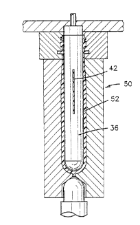
Figure 7 shows the lower end of a blow core 36 which
includes a slot 38 extending from the base 40 of the core
part way up into the core. A plastic insert 42, which is
the internal wall member, is prepared by any suitable
method, as by injection molding, stamping, or the like. At
~- 16
. ~
- ~A~ 1 ~q~
93-413
the region that is to extend completely across the hollow
space of the preform, the insert includes a solid portion 44
as shown in Figure 9. Adjacent the solid portion 44, insert
42 has a frame-like configuration with two parallel bars 46
joined by curved portion 48 defining space 50, as shown in
Figure 10. The insert 42 is placed in slot 3B of core 36
and follows the contour of the core. Thus, insert 42 has a
solid portion where it is to be formed into an internal wall
member extending completely across the hollow space of the
preform, and it is a frame with an empty middle below the
bottom terminus of the solid wall portion 44.
In accordance with Figure 11, core 36 having insert 42
therein is placed in injection mold 50, molten plastic
injected therearound to form preform 52 welded to insert 42
by the molten plastic entering the mold during injection,
while bars 46 and portion 48 keep the molten plastic from
entering into space 50. The resultant preform 52 is shown
in Figure 12. Edges 54 of insert 42 at least in the area of
solid portion 44 may be wider than slot 38, so that said
edges become surrounded by the molten plastic entering the
injection mold around core 36. Edges 54 may be provided
with serations 56 as shown in Figure 13 in order to increase
contact between the edge and the incoming hot plastic and to
facilitate fusion between the edge and incoming plastic.
.,~ .
CA21 4725~
93-413
Thus, in operation, insert 42 is placed by a robot
tightly into slot 38, the injection mold closed, and the
plastic injected. Edges 54 are surrounded by molten, or at
the very least very hot plastic, to the effect that the
edges and the plastic fuse. The frame portion of the insert
serves the purpose of preventing the molten plastic from
flowing into the slot, which remains empty below the solid
portion of the insert. It is often necessary to keep bottom
48 of insert 42 from melting, as it faces the injection gate
lo and thus the hottest entering plastic. To that end, bottom
48 is increased in thickness to keep the entering plastic
from melting it entirely and thus breaking into slot 38.
The warm preform 52 is then placed in a blow mold 58 as
shown in Figure 14 and a container of the present invention
formed therefrom by blow molding.
The thus formed preform is brought to a temperature at
which blow molding can be accomplished which may be done by
heating a previously formed preform or forming the hot
preform in line with the injection molding operation and
suitably adjusting the temperature thereof, if necessary.
Heating the internal walls, if necessary, may be done by
circulating warm air inside the hollow space 60 or by
inserting heaters therein.
The warm preform is placed in a blow mold having the
configuration of the desired container, as blow mold 58 in
18
p~
2A~ 4~58
93-413
Figure 14, while blowing compressed air thereinto so that
the preform expands into shape 62 shown in dashed lines in
Figure 14, to effect biaxial orientation and axial
elongation. This procedure may be carried out with or
without one or more stretch rods to effect axial elongation.
The insert or internal wall member 42 will also expand to
the extent permitted by the blow mold. The particular blow
mold shown in Figure 14 has an internal configuration which
allows the formation of a plastic container 64 shown in
Figure 15, although naturally other configurations may be
selected. Naturally, if the desired final configuration
includes at least two adjoining lobes connected together by
depressions, the blow mold will have this configuration.
Similarly, if an axially, inwardly directed bottom part is
desired as shown in Figure 15, the blow mold will have this
configuration. The preform will expand into the shape
permitted by the blow mold, and the internal walls will also
expand correspondingly.
Thus, blow molded, plastic container 64 is formed
having a neck portion 65 defining an opening 66, a bottom
portion 67, a body portion 68 as a generally tubular body
portion interconnecting the neck portion 65 and the bottom
portion 67. Neck portion 65 is provided with external
threads 69 corresponding to the threads on the preform if a
threaded preform is used to serve as the site for attachment
.~, 19
CA~l 4q2:~
-
93-413
of a closure on the container. Bottom portion 67 may have
an axially, inwardly directed generally conical base 70.
Alternatively, the bottom portion may exhibit protrusions
(not shown) upon which the bottle may rest, termed feet, as
well known in the art. In such a bottom configuration, it
is preferred to position the internal wall so as to
intersect opposing feet symmetrically. Container 64 also
includes shoulder portion 71 connecting neck portion 65 and
tubular body portion 68.
Container 64 is provided with at least one internal
wall 72 which corresponds to the internal wall 42 of preform
52 and which extends completely across hollow space 73
within container 64. As can be seen in Figure 15, internal
wall is limited in extent to body portion 68, but if
desired, can also extend down to axially inwardly directed
part 70 as shown in Figure 18 by internal wall 72' to also
support this portion of the container.
Internal wall 72 is securely attached and preferably
bonded to the container, as in Figure 15 to the body portion
68, thus providing a firm support for the container walls.
As shown in Figure 16, container body portion 68 may
define adjoining arcuate lobes connected together by
depressed regions or depressions 76, particularly suitable
for a handgrip in a large sized container. Naturally,
alternate shapes can be provided. Internal wall members 78,
.~?.~ ''.
p~
~A21 4-~25~
93-413
in this embodiment are provided in hollow space 73 bonded to
depressions 76 forming four arcuate lobes and providing
support therefor. The supported handgrips thus provided
will not evert as the bottle is pressurized.
In the embodiment of Figure 17, a single internal wall
member 80 is shown with lobe 82 being smaller than lobe 84
and with the internal wall crossing hollow space 73 spaced
from the center thereof. The internal wall 80 is bonded to
depressions 83 and provides support therefor. In contrast,
the embodiment of Figure 16 shows lobes 74 of approximately
equal size and with the internal supporting walls crossing
the center of hollow space 73. As can be appreciated, the
present invention readily contemplates the use of one, two
or more internal supporting walls.
Figure 19 shows a container 90 of the present invention
including a threaded neck portion 91, shoulder portion 92,
body portion 93 and bottom portion 94 similar to the
embodiment of Figure 15, but in this case the bottom portion
94 includes a plurality of supporting fee 95 and the body
portion 93 includes a handgrip 96 with internal support
member 97. In this embodiment, upper portion 98 of support
member 97 is concavely curved. It has been found that the
upper edge of the internal wall is the cause of excessive
concentration of stress when the container is pressurized,
which may result in rupture of the container especially when
~'
Cd~ 1 49 2 58
93-413
pressure rises in an overheated storage space. The
embodiment of Figure 19 minimizes the stress concentration
by extending the inner wall above the upper edge of handgrip
96. As shown in Figure 19, the inner wall 97 curves
downward because in that way the greatest amount of thinning
of the wall occurs away from the indentation where a thicker
cross-section is desirable.
Internal member 20 includes a visual display for
displaying a pattern or the like such as a marking 21
thereon, material void areas 23 in the form of the pattern
or the member being shaped in a form 25 resembling the
pattern, as shown in Figures 1, 20 and 21, respectively,
which may be visible through the wall of the final container
in whatever form it may assume upon expansion of the preform
into the molded container.
A visual display of a pattern such as via a marking 21
on internal member 20 is the key to playing the game with
the container. Marking 21 will be in a form of a pattern
which communicates to the player, i.e. typically the
beverage consumer, that he or she has lost or won the game.
For example, marking 21 may be in the form of the phrases
"you win", "winner", "try again" or any other similarly
informative phrase, as shown in Figure 1. Also, marking 21
can be in the form of a symbol such as a smiling face or an
unhappy face for indicating results, or it may be applied
,~ ~
. .~
CA~ 1 49~5~
93-413
according to a predetermined color code. In addition to
games, the marking 21 can be used for purely decorative
reasons such as a colored panel, a cartoon character or even
a sports figure. Marking 21 may be formed on wall member 20
via etching, stamping of any number of fluid safe printing
methods. In addition, safe color films or the like can be
used for forming the various designs.
Also, the internal member may have a rectangular or
other shape having material void areas 23 to form the shape
lo of the message to be communicated, wherein the material void
areas 23, for example, may be in the shape of a "W", an "L",
or the words "YOU WIN", etc., as shown in Figure 3. As an
alternative, internal member 20 may be shaped in the form 25
of a sign or signal communicating the results of the game.
That is, the internal member may be in the form 25 of the
word "WIN" or "LOSE", as shown in Figure 4, or more
succinctly, "W" or "L". In this version, internal member 20
would include side supports 27a and 27b for attachment to
the preforms or containers, as discussed below.
The wall member 20 having marking 21, cut outs 23, or
form 25 may be fabricated by any desired or convenient
method, as by injection molding or extrusion, stamping or
any other conventional forming technique. For the versions
of wall member 20 having material void areas 23 and forms
25, the material forming the internal wall may be cut via
CA~ 1 492~
g3-413
any cutting implement, manually or automatically such as by
stamping or may be molded into the desired shape. In the
embodiment of Figure 1, the wall member 20 has a solid
configuration. Such a solid configuration is desirable as
the initial configuration from which the material void areas
versions of the internal wall are formed, as shown in Figure
3. These embodiments of the internal wall member also
provide internal support for the final blow molded container
against eversion or other deformation under pressure.
The present invention thus provides a simple,
convenient and economical method for preparing a preform
with an internal wall having a marking 21, material void
areas 23, or form 25 and for internal support. Internal
wall 20 may be limited in extent to the body portion of the
container as shown in Figure 1, or may have any desired
length, as extending all the way to the bottom portion to
provide support for the bottom portion, or extending all the
way up to the neck portion. Thus, the present invention
offers a versatile and convenient procedure for preparing a
variety of embodiments.
Internal wall 72 is securely attached and preferably
bonded to the container, as in Figure 15 to the body portion
68. Similar to as discussed above, and referring to Figure
22, internal wall 72 includes visual displays such as the
marking 76, or material void areas or is specifically shaped
24
~ . .
$~J
C~l 4~25~
.
93-413
into a form, similar to as described above for the preform
(see Figures 1, 20 and 21), all of which communicate the
results of a game to be played with the container. Thus the
container is formed into a game piece while the internal
wall also provides a firm support for the container walls.
To institute the game using the container as a game
piece, the marking is hidden from the participants until
they will have performed an action that is to be rewarded by
winning, i.e., becoming entitled to a prize. For example,
lo the container, which is transparent, is filled with a
beverage whose color obscures the marking. The participant
must acquire the container and at least partly consume its
contents to reveal the winning marking. Alternatively, the
marking may reveal itself by other changes in ambient
conditions or location that is initiated only after the
container is first opened or otherwise irreversibly
transferred to the participant, as by non-returnable removal
from a "hidden" storage, as from a vending machine.
It is to be understood that the invention is not
limited to the illustrations described and shown herein,
which are deemed to be merely illustrative of the best modes
of carrying out the invention, and which are susceptible of
modification of form, size, arrangement of parts and details
f~
CA~`i 4~258
93-413
of operation. The invention rather is intended to encompass
all such modifications which are within its spirit and scope
as defined by the claims.
r ~
~'