Note: Descriptions are shown in the official language in which they were submitted.
2149798
SJ-9315CA - 1 -
TITT.F.: VART~RT~T~' VT~'.NTURI FOR p~F~u~TIc CONVEYING SYSTT~'.M.
FTT~'.T.n OF THE INVENTION
The present invention relates to an induction or
venturi device as a replacement for a mechanical feeding
device to move different types of materials into a
pneumatic conveying system.
BACKGROUND OF T~F. INVT~'.NTION
There are currently available different types of
induction or venturi devices that can be used in pneumatic
conveying systems. Once such device is described in my
issued United States Patent 5,002,092.
A typical venturi works on a principal of
converting velocity pressure into static pressure in the
diffuser section of the venturi.
A fan or blower is used to produce a flow of
primary air through the nozzle of the venturi device. This
flow or jet of air induces a vacuum within the venturi body
to draw in secondary air which in a conventional unit
enters through the same inlet that the material is fed to
the venturi body. With such an arrangement, it is
difficult to control the secondary air to material ratio
which is very important when working with different types
of granular materials such as styrofoam beads and the like.
In my own earlier patented construction, the cone
or nozzle is adjustable in its position to accommodate
different sizes of blower units. In known constructions,
the nozzle is permanently mounted within the venturi device
making it difficult to adapt these constructions for use
with different sizes of blowers.
2149798
SJ-9315CA - 2 -
srn~MARy OF THF INVFNTION
The present invention provides a venturi device for
use in an pneumatic conveying system in which the device
comprises a housing having a material feed inlet through
the housing, an open downstream end from which the material
introduced at the material feed inlet is carried way from
the housing, an open upstream end fitted with a nozzle in
the form of a frustoconical member having open forward and
rearward ends and a downstream taper and through which
primary air is fed to produce a vacuum in the device. The
device also includes an additional air inlet through which
secondary air is drawn by the vacuum and the additional air
inlet is adjustable in size to accommodate different air to
material mixture ratios within the device.
According to an aspect of the present invention,
the nozzle is releasably secured and replaceable with other
nozzles of different lengths and downstream opening
diameters in the housing to accommodate different primary
air sources used with the device.
BRIF.F DESCRIPTION OF THE DRAWINGS
The above as well as other advantages and features
of the present invention will be described according to the
preferred embodiments in which;
Figure 1 is a perspective view of a venturi device
according a to a preferred embodiment of the present
invention;
Figure 2 is an enlarged perspective view of the
main housing of the venturi device of Figure 1 when
partially disassembled;
Figure 3 is a sectional view through the main
housing of the venturi device of Figure l;
Figure 4 is a view similar to that of Figure 3 but
using a substitute nozzle;
2149798
SJ-9315CA - 3 -
Figure 5 is an end view of a clamp member used in
the venturi device of Figure l;
Figure 6 is a sectional view through the clamp
member of Figure 5.
DF~TATRF~n DF~'~CRIPTION Acco~nING TO T~F~' p~F~FT~R~T~n
FMRODIMENTS OF T~T~' p~T~'~T'NT INVT'.NTION
Figure 1 shows an overall venturi device generally
indicated at 1. This device is used in a pneumatic
conveying system incorporating a blower s at the upstream
end of the system. The device can be used to feed granular
material such as grain, styrofoam beads, plastic pellets
and many other types of granular materials. It also has
particular application for cut pieces of plastic and paper
or foil material. When working with such materials it is
important to be able to control the blending of secondary
air with the material as described below as the air to
material ratio is critical for proper conveyance through
the system.
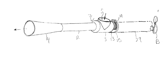
Venturi device 1 comprises a main housing 3 having
a material feed inlet 5, an open upstream end 9 and an open
downstream end 7. The downstream end of the housing is
fitted to an acceleration tube 2 which is in turn fitted to
a static regain chamber 4. As described in my own above
referenced patent acceleration tube 2 has a length of 3 1/2
to 4 times its diameter. This length to diameter ratio
provides excellent air flow and static pressure
performance.
As earlier noted, blower B is provided at the
upstream end of the system and provides a source of primary
air. In the particular example shown, the blower is
separated from the venturi device by a conduit extension 29
which is connected to the upstream end of housing 3 by
means of a quick connect clamp 25 which is best shown in
2149798
SJ-9315CA - 4 -
Figures 5 and 6 of the drawings and which will be described
later in detail.
As seen in Figures 2 and 3, a frustoconical nozzle
21 is provided interiorly of housing 3. This nozzle is
open at its forward end which aligns with the upstream end
of housing 3 and has a downstream taper to its open
rearward end directed at the downstream end 7 of the main
housing.
The primary air provided by blower B is forced
through the constriction provided by the nozzle to create a
venturi or vacuum effect within the housing. The vacuum is
fed by a source of secondary air which is drawn in through
an air inlet 11 located between the material feed inlet 5
and the upstream end 9 of the housing. The amount of
secondary air introduced to the housing can be varied by
adjusting the effective size of air inlet 11. This is
accomplished by means of a band 13 having a screened slot
19. The band wraps around the housing over air inlet 11
and is tightened by a threaded bolt 17 which fits through
the mating ends 15 of the band. sy loosening bolt 17, the
band 13 is rotatable on the housing to vary the positioning
of slot 19 over air inlet 11 to change the size of the air
inlet.
In known venturies, all of the secondary air is
provided through the material inlet which cannot be
adjusted in size to vary the amount of secondary air
introduced without simultaneously varying the amount of
material introduced. With the present invention, the
secondary air inlet is in no way associated with the
material inlet.
A further unique feature of the present invention
resides in the fact that nozzle 21 is releasably secured
within housing 3 and therefore replaceable with other
21~9798
SJ-9315CA - 5 -
nozzles making the system compatible with various different
blower capacities. For example, Figure 4 shows housing 3
fitted with a nozzle 21a which is shorter in length and has
a larger diameter downstream opening than nozzle 21.
Therefore, the setup of Figure 4 would accommodate a
different blower capacity than the setup of Figure 3.
Band 25 which as earlier described provides a quick
connection between housing 3 and the upstream conduit piece
29 also provides a clamp for releasably securing the nozzle
21 within the housing. This band as shown in Figure 5
includes a toggle 26 for a simple and fast opening and
closing of the band. As seen in Figure 6, the band
includes a central sealing member 27 on its interior
surface with a pair of recessed regions 28 to either side
of the sealing member.
The fitting of the band to the housing, the nozzle
and the upstream conduit member 29 is best shown in Figure
3 of the drawings. Here it will be seen that housing 3 has
an outwardly turned lip 8 and the nozzle 21 which has a
mouth the same size as that of the housing has a
corresponding outwardly turned lip 23. This lip sits
directly against the lip 8 on the housing. The two lips 8
and 23 are trapped within one of the recesses 28 beside the
center seal 27 of band 25.
The upstream conduit member 29 includes its own
outwardly turned lip 31 which sits in the recess 28 to the
other side of the center seal 27 of the band 25 and when
the band is tightened down by the toggle 26 all of the
three lips 8, 27 and 31 of the respective components are
held in pôsition by the band.
From the above, it will be easily understood that
by simply removing the band from the system, nozzle 21 can
be pulled out of the housing 3 and quickly and easily
- 2149798
SJ-9315CA - 6 -
replaced with another nozzle such as nozzle 21a shown in
Figure 4 of the drawings.
In operation, the venturi device is preferably
setup as shown in Figure 1 with material inlet 5 facing to
the top of the divice. This allows a gravity feed of
material to the device. The primary air passes through
nozzle 21 creating a vacuum and drawing the material into
the housing. The vacuum also draws secondary air into the
housing through air inlet 11. The size of the opening of
the secondary air inlet is the adjusted to obtain a proper
material to air ratio in accordance with weight, shape and
flow characteristics of the particular material introduced
to the system. The positioning of the secondary air inlet
behind the material inlet allows the secondary air to blend
directly into the stream of material thereby assuring
proper air to material ratios. It also reduces suction at
the material inlet for better control of the volume of
material entering the system through the material inlet.
As earlier described, the air injector nozzle is
also made so that it can readily be replaced with a nozzle
of proper size, diameter and length to suit the conveying
system. This feature is important due to the fact that
systems vary in static pressure flow resistance and blower
sizes as a result of variable lengths of systems and the
types of materials being handled. For example, the bulk
density will vary from one material to the next.
Furthermore, different materials have different flow
coefficients as a result of friction on the inside of the
wall of the duct and the material orientation in the
airstream.
With the quick nozzle change feature of the present
invention, a system can be easily tested with different
nozzle sizes and fitted with the appropriate nozzle
directly on site.
2149798
SJ-9315CA - 7 -
Although various preferred embodiments of the
present invention have been described herein in detail, it
will be appreciated by those skilled in the art, that
variations may be made thereto without departing from the
spirit of the invention or the scope of the appended
claims.