Note: Descriptions are shown in the official language in which they were submitted.
214~23
.~. .
Sterilising Device for Endo~icop~ Pa~sage~ ~
, j..
The invention relates to a sterilisiing device for
endoscope passages in accordance with the precharac-
terislng portion of Claim 1.
Conventional endoscopes, i.e. flexible or rigid elongate
devices, which may be introduced into the human body,
with or without an optical syistem have one or more
passages open at both ends, e.g. flushing or working
~ paqsages, which open out into the operation field during
usage. In order to prevent infection, it is necessary
for these passages to be~sterilised before each use.
15 ~ ~
The ~ sterilisation of such passages is, however,
difficult, particularly with the 1exible endoscopes used
e~.~g.~ in angiology. Such endoscopes include materials
which are he~at resistant only to a limited extent so that
~ autoclaving is excluded as a ~ethod of sterilisation.
Further possibilities, such as treatment with acetylene
oxide gasi;or gamma radiation, require expenisive central
equipment~ and are thu~ not practical, or only to a
limited extent~.
` ~ - `
A~change has therefore been made to flush the endoscopes
through in situ with hydrogen peroxide. For this
purpose, one~r endl of,~he passage is connectçd via an
adapter to a supply veissel, which is deformable to a
30 ~- limited extent and in which a rupturable ampoule
-~- containing hydrogen peroxide is disposed. The passage is
acted on by a vacuum via its other end. After the vacuum
hais~ built up in the passage the ampoule is broken by
compressing the supply vessel walls and the released
,, ~ . .
,, . ~ .:
,,
;~ :
, ~ ,
,, -
, , ~ , . . ... .. . .. .
- ~ . 21~23 ~:~
For this purpose, one end of the passaqe is connected vla
an adapter to a supply vessel. which is deformable to a
limited extent and in which a rupturable ampoule
containing hydroyen peroxide is disposed. The passage is
acted on by a vacuum via its other end. After the vacuum
has built up in the passage the ampoule is broken by
compressing the supply vessel walls and the released
hydrogen peroxide is sucked through the passage thereby
effecting the steriliqation. A corresponding method is
described in e.g. Hyg. Med. Vol.17, No.12, 1992 on pages
537-543.
~ Working with this known sterilising device does, however,
have a number of disadvantages. One disadvantage is that
the destruction of the ampoule by compressing the supply
vessel walls is sometimes only possible with the
.
application of a large force and in some cases is not
possible at all. A further disadvantage is that small
fragments of the ampoule are sometimes sucked into the
-~ ~ 20 - ~ ~passage. ~ ~Finally, it is questionable whether the
st~erilisation may be conducted ~n a reproducible manner
with the described known supply vessels. Thus it is
necessary that the release of~ the sterilisation agent
occurs suddenly through a relatively large opening
because it is only in thi~ manner that an adequate
atomisation of the sterilisation agent in the passage is
poss~ible. Whether such an opening in the ampoule may be
achieved in all cases by compressing the supply vessel is
questionable. , ` ,~ ,; ~ ! i ii
In order to meet this problem it has been contemplated
that the membrane be constructed such that it ruptures
Translator's note:
Ihe words appearing above which are underlined do not appear in the
revised ~ersion of page 2 which was filed in the International Phase
but instead appear on page l of the original text. They have been
included in this translation because German word order is different
to English word order and their inclusion is therefore necessary to
render the translation of the amended pages ccmprehensible and
consistent with the translation of the original text.
. .. , .. j.. , ... ,, . .,. . ,.. ,: --
~ ~ 2149~23 I ~
automa~ically after the application of the vacuum. This
would be theoretically possible if the membrane is
provided with a weakened zone in the region which
experiences the greatest deformation due to the ~acuum.
Such membranes are, however, extremely difficult to
manufacture. Problems are caused particularly by the
fact that such a membrane must be guaranteed to tear when
acted on by a vacuum. On the other hand, the same
~embrane must ensure a gas-tight enclosure under normal
pressure conditions of the hydrogen peroxide contained in
the supply vessel, even over relatively long storage
~ periods. The two requirements may only be reconciled
with one another with difficulty so that this solution is
currently scarcely practicable.
In this connection, reference is also made to
~- EP-A-0452780. In the device disclosed herein, the space
to be sterilised is cannected via an adaptor to a supply
vessel which contains hydrogen peroxide. A destructible
membrane is -provided in the ~aptor and a needle is
provided in the supply vessel. When the adaptor is
inserted into the ~upply vessel the needle destroys the
membrane~and the hydrogen peroxide is released. This
-~ device is, however, relatively complex to use.
~- ~ 25
i,-, ~ ,
-~ It is thus the object of the inven~ion to provide a
sterilising device which may be simply manufactured and ;
whiçh may be ysed wit,hQut problem~and in a functionally
reliable manner in the course of the sterilisation.
This object is solved with a sterilising device which has
the characterislng features of Claim 1.
.~ ":
~ The principle of the solution resides in that a needle is
. ..
:~,
" .
~- ` 2149~2~ :
.~ , . .. .
3A
so arranged in the sterilising device that its tip points
from the exterior towards the membrane. The membrane and
needle are constructed to be relatively movable in the
sterilising device towards one another to the effect that
the membrane is punctured by the tip of the needle in the
course of the relative movement and releases the enclosed
æterilising agent, particularly hydrogen peroxide.
The advantages of the sterilising device in accordance
with the invention are clear. Thus the needle arranged
in the sterilising device ensure the destruction of the
- membrane and thé desired release of the sterilising agent
occurs reliably and without difficulty. Nearly all
conventional gas-tight membranes may be used. Various
needles can be used for the puncturing, depending on the
membrane characteristics, whereby the desired rapid
release of the sterilising agent can occur in all cases.
~.
It~is~ e.g. possible to make the membrane from a flexible
20 ~ ~material ~which tears when punctured. In such a case a
simple~compact needle is sufficient~ for the puncturing.
On the other hand, however, the membrane can also be
manufactured from a tear-resistant piercable material.
25 ; In~this modification the needle must then be constructed
in the form of a hollow cannula through which the
- sterilising agent can escape out of the supply vessel
into the endoscope passage. The modifications which are
po~sib1e in this connection will be discussed again
~- 30 below.
.
-~ Adyantageous embodiments of the invention are protected
in Claims 2 to`lO.
~,: : , :
k
, . . .
,,~
., :
~i",
'~' 2149D23
On the other hand, however, the membrane can also be
manufactured from a tear-resistant piercable material.
In this modification the needle must then be constructed
in the form of a hollow cannula through which the
sterilising agent can escape out of the supply vessel
into the endoscope passage. The modifications which are
possible in this connection will be discussed again
below.
Advantageous embodiments of the invention are protected
in Claims 2 to 10.
.
It is pro~ided in an advantageous manner in Claim 2 that
the needle is fixedly arranged and the membrane is
constructed to be movable. The tip of~the needle is
directed particularly towards a central region of the
membrane. The described construction permits a
parti~cularly simply and~ functionally reliable
mplementation.
20 ~ ~ ~
Thus it is e.g. possible in ~ccordance with Claim 3
fixedly to connect the supply vessel and the adapter
toge~ther in a defi~ed position and to construct the
membrane in the supply vessel such that it is sucked
~;~ 25 against the tip of the needle and thereby punctured on
application of the vacuum. The sterilisation of the
- ~ endoscope passage may be conducted, nearly automatically,
- with a minimum of operational effort with such a
sterihising device.
s ~ It is possible in accordance with Claim 4 to make the
,. .
membrane from a material which tears when damaged. When
using such a membrane it is ensured in all cases that the
release of the sterilising agent occurs suddenly when the
:,: . .
";
,=~
`
;
2149923
membrane is punctured with the tip o~ the needle.
However, such suitable membranes generally comprise a
different material to the supply vessel and may thus not
be manufactured integrally with it. A further embodiment
in accordance with Claim 5 thus provides that the supply
vessel is constructed of two components to be connected
together in a vacuum-tight manner. The membrane, which
comprises suitable material, can then be clamped with its
edge between the two components in the connection region.
The selection of the membrane materials can thus be made
independently of the selection of the material of the
vessel in an advantageous manner.
In the embodiment which has just been described the
needle is generally arranged in the outer portion of the
supply vessel. It is however also possible and just as
good to construct the-needle in accordance with Claim 6
in the adapter. Such a construction has a number of
advantages. The main advantage is that the adapter is
generally re-used whilst th~ supply vessel is a
dispos`able item. Since the construction of the needle
necessitates a relatively expensive manufacturing
process, the manufacturing costs can be substantially
minimised in this manner. A further advantage of the
sieparation of the needle and supply vessel resides in
that inadvertent piercing of the membrane (e.g. in the
event of pressure fluctuations - transport in an
aeroplane) is preivent!ed.
A further substantial advantage resides in that the
membrane in this embodiment need now no longer be
disposed in the interior of the supply vessel. It is
; instead possible in a further advantageous embodiment in
,~, , .
~ . 21~923
accordance with Claim 7 to secure the membrane to the
edge of the supply vessel by welding or adhesive which
constitutes a considerable constructional simplification
of the supply vessel.
The previously discussed embodiments relate principally
to a sterilising device in which the movement of the
membrane with respect to the tip of the needle occurs as
a result of the vacuum which is applied.
The movement of the membrane with respect to the needle
can/ however, occur in some other manner. Thus it is
possible in accordance with Claim 8 to construct the
supply vessel and adapter such that the supply vessel is
movable in a vacuum-tight manner within the adapter. If
the needle is~arranged in the~adapter and the membrane is
arranged at a suitable position in the supply vessel it
i8 poissible to puncture the membrane by simply pushing
the supply vessel into the adapter.
It~is particularly advantageous4in this embodiment that
the s~e1ection of the membrane material is subject to
virtually no limitations. Since the membrane need no
longèr deform, it can comprise flexible material, as
previously, and also inflexible material. Further
possibilities, which are advantageous in this connection,
are produced if a continuous hollow cannula, as proposed
in Claim 9, is provided as the needle. In this case, in
~i accordance with~Clai~ io, the membrane can comprilse a
~ tear-resistant puncturable material. It is thus even
possible in this connection, if desired, to make the
membrane from the same material as the supply vessel.
When the vacuum is applied the steriliRing agent can
escape equally well via the passage through the membrane
, j,,
,,:,, ~
,,
21~23
.
constituted by the hollow cannula as is the case with a
tearable membrane.
: .
The invention will be described in more detail below with
reference to a number of drawings illustrating different
exemplary embodiments, in which:
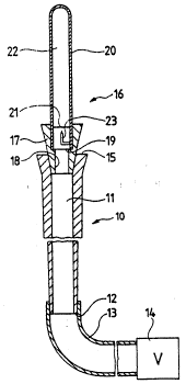
Fig. 1 is an overall view of an endoscope passage with
- a sterilising device positioned thereon,
lQ - ~
Fig. 2 is a scrap view on an enlarged scale of th ;
region of the supply vessel carrying the
membrane before contact with the needle, `;
Fig. 3 shows the region illustrated in Fig. 2 after
contact of the membrane with the needle,
-, ~
.,
~ Fl:g. 4 is~a scrap view on an enlarged scale of the
t~ arrangement of a membrane in a two-part supply
~ 20 vessel,
t~
Fig. 5 shows a further possibility for mounting the
needle,
Fig.~6 shows an exemplary embodiment in which the
needle is constructed as a hollow cannula,
~, ~
` Fig. 7 shows an exemplary embodiment in which the
i needlelis!arranged inithe adapter,
~ 30
q~ Fig. 8 is like Fig. 7 and shows an exemplary
~ : ~ embodiment in which the needle is arranged in
the adapter, but with the difference that the
membrane is constructed in the interior of the
.,
?, ~
1~' '~ .
~ ` 2149~23
supply vessel, and
Fig. 9 finally shows a further exemplary embodiment in
which the supply vessel is constructed to be
advanceable over a first abutment into the
adapter.
..
~n endoscope 10~, in which a passage ll is~formed, may be
seen schematically illustrated in Fig. l. ~The passage ll
- lO is in communication with a vacuum pump 14~via a hose 13
arranged at one end 12 of the endoscope. Arranged at the
other end lS~ of the endoscope 10 is an exemplary
- embodiment of the sterilising device 16~in accordance
with the invention. The~sterilising device 16 comprises
15 ~ ~an~adapter 17, with~is inserted in~a vacuum-tight manner
into~ the~ paRsage ~ The adapter 17 ~has a through
passage 18~ whose~1Ower~end~opens~out into the passage ll
and~ ns ~ ed~ into~whose upper ~end region there- is a
suppiy~ves~se1~providsd~with an~opening,l9~such that the
2~0~ op,ening~l9''is directed towards the passage lI. The
supp1y ve'~s,sel 2~0~and the adapter 17,are so ~constructed
that,~there is a~vacuum-tight connection ~between the
passage'll~and~the sndoscope 10 and the upply vessel 20.
25~ Xrrahged~in~the supply vessel 20 is a membrane 21 which
define~s~a~ssa1ed~'region 22 in the vessel 20. Disposed
within this sealed~region 22 is the sterilising agent.
;,~,
Hydrogen `pero'xi~e l~s~ palrticu1arly suitable as ithe
3~0~ ~ st;erilising agent. However, e.g. ethylene dioxide could
also be c~onsidered~. Basically all liquid or liquifiable ;~
ste-rilising agents~which are atomisable or vaporisable on
the sudden application of a vacuum are basically
,"~ uitable.
~", "~
. ~,, . . 2l4sa23
9 l ~
Arranged in the supply vessel is a needle 23 whose tip is
directed from the exterior towards the membrane 21.
In the state shown in Fig. 1 no vacuum is applied to the
passage 11. Figs. 2 and 3 show in detail what occurs
when a vacuum is applied.
. ~ '.';
The region of the supply vessel 20 which carries the
membrane 21 and the needle 23 arranged below the membràne
may be seen in the detailed view of Fig. 2. If vacuum is -
now applied, the membrane consisting of a flexible `
; material is deformed in the direction of the arrow 24,
moves into engagement with the tip of the needle 23 and
tears, as shown in Fig. 3.
~ ~ ~
After~ tearing of the membrane, the sterilising agent
conta~inéd~in~the previously sealed region 22 suddenly ~-~
vapori~sès~or~atomises and i8 sucked~in this form into the
pas8age~1} in the endoscope 10. Optimal contact between
20:: the~-wa~lls~ of ~ the passage 10 and the sterilising agent is
possible in this manner.
Fig.~ shows~a further exemplary embodiment of a supply
ves8el~ 40~ It may be~ ~een~that the~supply vessel 40
- 25~ ~ compris~es~ an inner portion 21 and an outer portion 42.
Clampéd~between the portions 41 and 42 is a membrane 44
~ consltructed with a thickened edge 43. The outer portion
i 42 carries;a needle 45 whose tip is directed towards the
membra~e~44.
,;- 30
The arrangement of the membrane in the illustrated manner
represents~ a ~particularly simple possibility for
manufacturing the supply vessel and membrane from
different materials.
~: :- :
` ~ . 21~9!323 :
''~''
Figs. 5 and 6 show further exemplary embodiments of
supply vessels 50 and 60, respectively. In both case~
the supply vessels are shown as being of one-part
construction again for rea~ons of clarity. It is,
however, also of course possible to clamp the illustrated
membranes 51 and 61, as shown in Fig. 4, between two
separate supply vessel portions.
Figs. 5 and 6 show different possibilities for the
arrangement or construction of the needle. Thus a needle
52, which is carried by a web 53 extending transversely
through the supply vessel, may be seen in Fig. 5~ This
type of fastening of the needle can be more stable than
the one-armed fastening shown in Figs. 1-4.
Fig. 6 shows a needle 62 which is constructed as a hollow
; cannula. The advantage of such a needle resides in the
fact that the sterilising agent can also escape through
the hollow needle 62 in doubtful case after piercing the
membrane 61. This is particularly advantageous if the
membrane does not tear in the d~sired manner.
Fig. 7 shows a further embodiment of a sterilising device
, ~
which differs fundamentally from the exemplary
embodiments shown above. The endoscope 10 with the
~-~ passage 11 may again be seen. An adaptor 71 is inserted
into the passage 11 at the proximal end 15 of the
endoscope 10. The adaptor 71 has a through passage 72
- into w~ich theipassagé 11 opens. Inserted into the upper
end region of the through passage 72 is a supply vessel
73 containing the sterilising agent. Thus far there are
no differences to the exemplary embodiments shown above.
A substantial difference resides, however, in the fact
. ,~, .
~, ~
,
.
."~,
,'`
.,
~ 214~2~ :
11
that the needle 76 is arranged in the through passage 72
in the adaptor 71. The point of the needle 76 is
directed towards a membrane 74 which is welded onto the
edge 75 of the supply vessel 73. This arrangement of the
membrane 74 at the open end of the supply vessel 73 also
represents a difference to the previously shown exemplary
embodiments.
If vacuum is applied to the passage 11, the membrane 74
is pulled in the usual manner over the tip of the needle
76 and thereby destroyed. The sterilising~agent situated ~`
within the supply ves~el 73 can escape into the passage
11.
A further exemplary embodiment of the sterilising device
80 is shown in Fig. 8. The needle 81 is arranged in the
~; adaptor 82 in this case also. An important difference to
Fig. 7 is that in this case a supply vessel 83 is
provided~which carries the membrane 84 in its interior.
This exemplary embodiment is possibly more difficult to
- manufactllre than that shown i~ Fig. 7 (under certain
circumatances a two-part construction of the supply
vesssel is necessary in this case if it is desired to
~ fall back on certain membrane materials). On the other
; - 25 hand, the exemplary embodiment shown in Fig. 8 has the
advantage that~the membrane is relatively well protected
in the interior of the supply vessel 83 and cannot easily
be damaged by inadvertent scratches etc.
FIg. 9 shows a further exemplary embodiment of a
sterilising device 90 which operates in a fundamentally
different manner to the previously shown exemplary
embodiment. An adaptor 91 with a through passage 98, in
~ which a first abutment 92 is constructed, is provided in
: ~ :
i~
~ 2149~23 ~:
12
this case. A supply vessel 93 is slid into the adaptor
91 against this first abutment 92. The open end of the
supply vessel 93 is closed with a membrane 94.
Arranged in the adaptor 91 is a needle 95 whose tip is
directed in the usual manner towards the membrane 94.
In the illustrated slid-in position there is a gap 96
between the tip of the needle 95 and the membrane 94.
.
The abutment 92 is so constructed that the supply vessel
may be advanced over this abutment deeper into the
adaptor 91 up to a second abutment 97, if a suitable
force is applied. In the course of this movement the
membrane 94 come$ into engagement with the tip of the
needle~95 and is destroyed.
.
In~ ~the exemplary embodiment shown in Fig. g the
destruction of the membrane is thus no longer brought
20 ~ about~ by ~the deformation of the memebrane caused by the
vacuum. It is effected instead ~y bodily movement of the
membrane 94 against the needle 95.
It will be clear that in this exemplary embodiment shown
~ in~ Fig. 9 the membrane material no longer need
necessarily be of flexible construction. Furthermore, if
a hollow needle is selected as the needle, it is even
sufficient if the membrane material is merely
~ ~ ~; ' ' '' ' pierceable '. ~
~- On the other hand, destruction of the membrane caused by
, "~, ~ ,
the vacuum is also possible with the exemplary embodiment
~---; - shown~ in Fig. 9. Thus the first abutment 92 in the
adaptor 91 could be omitted. The tube should then be
, ~
, , :
.~, , ~ ,
~:
~. ~
, , . ~ .
:
, . . .
, ~ ~
2149923
13
introduced into the through passage 98 only so far that
experience shows an adequate seal is ensured. The supply
vessel 93 is then sucked into the adaptor 91 against the
abutment 97 by the applica~ion of the vacuum. This
S possibility would make substantial automation of the
sterilisation process posslble.
The needles are indicated only schematically in each case
in the illustrated exemplary embodiments. They can be
constructed as steel needles which are connected to the
supply vessel or adaptor, which comprise plastics
material, for instance by means of plastic arms. The
needles can, however, also consist of suitable plastics
material of suitable hardness and tip construction and,
if desired, can even be constructed integrally with the
supply container or adaptor.
:' ~
: ~ 4
' ':
.~ , '
~ `
.-
,
,~. . . .
V'~'~
~, ,