Note: Descriptions are shown in the official language in which they were submitted.
21 X9977
1
OPTICAL TAPE DUPLICATOR
BACKGROUND OF THE INVENTION
This invention relates to tape recording, and more particularly to optical
tape recording.
Currently there are two main types of optical tape recorders. These two main
types of optical
recorders differ in how an optical recording head moves across the optical
tape. The first type of
optical recording head is a rotary head that scans across the tape in a
helical scan pattern. The
rotary head usually includes at least two recording elements, so that each
revolution of the rotary
head records multiple tracks on the tape. Examples of rotary optical recording
heads are disclosed
in U.S. Pat. Nos. 5,239,528, 4,815,067, 4,807,213, and 4,661,941.
The second type of optical tape recorder employs an optical recording head
that moves
across the tape in a linear motion. The linear motion of the recording head is
transverse to the
motion of the tape itself. Linear recording heads use either a single
recording element, or an array
of recording elements. Typical linear optical recording heads are disclosed in
U.S. Pat. Nos.
S,I77,724 and 4,567,585.
The two existing types of optical tape recorders have generally performed
adequately.
However, both of these types are relatively slow at recording optical tape.
Their slow speed of
recording is one barrier to optical tape replacing magnetic tape as the medium
of choice for
recording and playing movies and other images. Another barrier is the lack of
a suitable optical
tape cartridge .
74078-33
21 X99 7 7
There is therefore a need for an optical tape duplicator that
can record optical tapes at the speed and at the cost required
by the consumer market.
These and other features of the present invention
will become readily appreciated from the following detailed
description when considered in conjunction with the accompany-
ing drawings.
SUMMARY OF THE INVENTION
In accordance with the present invention, there is
provided an optical tape duplicator, comprising: means for
emitting a beam of radiant energy into a recording zone; an
information bearing template-like master tape only having first
portions being transmissive to said beam of radiant energy and
second portions being non-transmissive to said beam of radiant
energy; an optical tape that is sensitive to said beam of
radiant energy; means for holding said template-like master
tape in intimate contact with said optical tape in said record-
ing zone such that said beam of radiant energy passes through
said transmissive first portions of said template-like master
tape causing said optical tape to be recorded by creating
respective indicia in said optical tape where said optical
tape was exposed to said beam of radiant energy.
In accordance with another aspect of the invention,
there is provided the optical tape duplicator as defined above,
further including: a radiation source for emitting said beam;
a supply platter for dispensing said optical tape; a take-up
platter for receiving said optical tape; a first clamping
r mechanism; a second clamping mechanism, said first clamping
74078-33
2a 21 4~ g 9 7 7
mechanism making intimate contact with said template-like
master tape in said recording zone, said template-like master
tape making intimate contact with said optical tape in said
recording zone, said optical tape making intimate contact with
said second clamping mechanism in said recording zone; and
means for rotating said take-up platter such that said
template-like master tape is held in intimate contact with
said optical tape by said first clamping mechanism and said
second clamping mechanism, and moved through said recording
zone allowing said beam of radiant energy to pass through said
transmissive first portions of said template-like master tape
causing said optical tape to be recorded by creating respective
indicia in said optical tape where said optical tape was
exposed to said beam of radiant energy.
In accordance with a further aspect of the invention,
there is provided a method for duplicating optical tape, said
method comprising the steps of: emitting a beam of radiant
energy into a recording zone; holding an information bearing
template-like master tape in intimate contact with an optical
tape having a recording surface sensitive to said beam of
radiant energy, said template-like master tape only having
first portions being transmissive to said beam of radiant
energy and second portions being non-transmissive to said beam
of radiant energy; moving said template-like master tape and
said optical tape held in intimate contact with each other
through said recording zone; and exposing said template-like
master tape and said optical tape to said beam of radiant
energy while moving through said recording zone so that said
74078-33
Zb 21 X9977
beam of radiant energy passes through said transmissive first
portions of said template-like master tape causing said
optical tape to be recorded by creating respective indicia in
said optical tape where said optical tape was exposed to said
beam of radiant energy.
BRIEF DESCRIPTION OF THE DRAWINGS
Fig. 1 is a diagram of an optical tape duplicator.
Fig. 2 is a diagram of a path taken by a beam of
radiant energy during the operation of the optical tape
duplicator of Fig. 1.
Fig. 3 is an exploded view of the transparent belt,
master tape, optical tape and support belt configuration of
Fig. 2.
Fig. 4 is a diagram of the optical tape shown in
Figs. 1, 2 and 3 after the optical tape has been recorded by
the optical tape duplicator of Fig. 1.
DETAILED DESCRIPTION OF THE PREFERRED EMBODIMENT
Details of illustrative embodiments of the invention
are disclosed in this section. However, it should be under-
stood that these embodiments merely exemplify the present
invention which may take forms different from the specific
illustrative embodiments disclosed. Therefore, specific
structural and functional details are not necessarily to be
interpreted as limiting, but as a basis for the claims. It
should also be understood that components illustrated in this
section are well-known to those skilled in the art. Therefore,
some of the details and refinements associated with these
components are not illustrated, but should be understood to be
74078-33
2c 21 e~9977
present. For example, such details and refinements would
include, but are not limited to, frames, motors, capstans,
rollers, tension controls, electronics, etc.
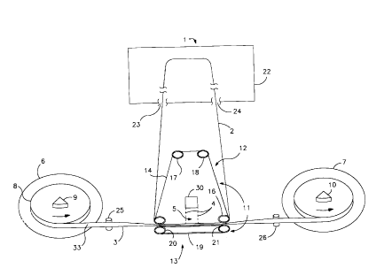
Referring now to Fig. 1, there is shown a diagram of
a preferred embodiment of an optical tape duplicator 1.
Referring now to Figs. l, 2, 3 and 4, duplicator 1 duplicates
information 36, contained on an information-bearing master
tape 2, as indicia 35 in an optical tape 3. In brief,
duplicator 1 includes an information-bearing endless master
tape 2 which contains prerecorded information 36. Optical tape
3 includes recording surface 33 that is sensitive to beam of
radiant energy 4. Master tape 2 makes intimate contact with
optical tape 3. While in intimate contact,
74078-33
3
master tape 2 and optical tape 3 are simultaneously passed through a recording
zone 5 and exposed
to beam of radiant energy 4. Exposure of master tape 2 and optical tape 3 to
beam of radiant
energy 4 causes information 36 stored by master tape 2 to be recorded in
recording surface 33 of
optical tape 3 as indicia 35. This recording process is repeated until the
supply of optical tape 3
is exhausted.
Optical tape 3 is dispensed from supply platter 6 before recording and
received by take-up
platter 7 after recording. Optical tape 3 is wound around spindle 9 attached
to the center of supply
platter 6. Similarly, recorded optical tape 3 is wound around spindle 10
attached to the center of
take-up platter 7 after recording. The configuration of optical tape 3 with
platter 6 or 7 is known
1 o in the recording industry as a "pancake" because of its shape. Both supply
platter 6 and take-up
platter 7 are rotatably mounted to a frame (not shown).
Preferably both platters 6 and 7 are mounted in the frame so that tape 3 is
dispensed
horizontally. Alternatively, platters 6 and 7 can be replaced by reels (not
shown) with side
supports that allow the reels to be mounted vertically in the frame. However,
horizontal platters
6 and 7 are preferred to vertical reels because horizontal platters 6 and 7
distribute the weight of
a fully wound optical tape 3 more uniformly than would vertical reels, and are
themselves easier
for the frame to support.
With continued reference to Fig. 1, duplicator 1 includes clamping device 11
for holding
master tape 2 and optical tape 3 in intimate contact with each other while
being passed through
2 o recording zone 5. Clamping device 11 comprises upper clamping mechanism 12
and lower
clamping mechanism 13. Upper clamping mechanism 12 comprises transparent belt
14 disposed
about rollers 15, 16, 17 and 18, and generally forms the shape of a four sided
polygon. Rollers
15, 16, 17 and 18 are rotatably mounted in the same vertical plane with each
other. Rollers 15,
16, 17 and 18 each have an axis of rotation perpendicular to the vertical
plane in which they are
2 5 mounted. Rollers 15 and 16 are laterally displaced from each other in the
horizontal direction and
rollers 17 and 18 are generally positioned above rollers 15 and 16, and are
also laterally displaced
from each other in the horizontal direction.
Master tape 2 is partially disposed about the lower portion of upper clamping
device 11.
Specifically, master tape 2 comes into intimate contact with transparent belt
14 at a point
3 0 intermediate rollers 17 and 15. While maintaining intimate contact with
transparent belt 14, master
21~9~?'
4
tape 2 follows transparent belt 14 downward around roller 15, along the bottom
surface of upper
clamping mechanism 12 formed by transparent belt 14, and upward around roller
16 until master
tape 2 breaks intimate contact with transparent belt 14 at a point
intermediate rollers 16 and 18.
Lower clamping mechanism 13 is comprised of support belt 19 disposed about
rollers 20
and 21. Rollers 20 and 21 are laterally displaced from each other in the
horizontal direction and
are also rotatably mounted in the same vertical plane that rollers 15, 16, 17
and 18 are mounted.
Rollers 20 and 21 also have an axis of rotation perpendicular to the vertical
plane in which they
are mounted. Optical tape 3 comes into intimate contact with support belt 19
at a point generally
positioned above roller 20. Optical tape 3 maintains intimate contact with the
upper surface of
lower clamping mechanism 13 formed by support belt 19 until optical tape 3
breaks intimate
contact with support belt 19 at a position generally above roller 21. Rollers
20 and 21 are
positioned in close proximity below rollers 15 and 16, respectively, such that
support belt 19 and
transparent belt 14 apply sufficient clamping pressure to hold master tape 2
and optical tape 3 in
intimate contact with each other while passing through recording zone 5 during
the recording
process.
Preferably, lower clamping mechanism 13 can move in the vertical direction
when
duplicator 1 is not recording to allow easy installation and removal of master
tape 2 and optical
tape 3.
As previously stated, master tape 2 is an endless tape partially disposed
about the lower
2 0 portion of upper clamping mechanism 12. The bulk of endless master tape 2
is stored in loop
chamber 22. In general, loop chamber 22 is an enclosed rectangular box with
two tape openings
23 and 24. Master tape 2 exits loop chamber 22 at tape opening 23, wraps
around the lower
portion of upper clamping mechanism 12, and reenters loop chamber 22 at tape
opening 24. The
width of the inside of loop chamber 22 is slightly wider than the width of
master tape 2. Loop
2 5 chamber 22 must be large enough to allow the bulk of master tape 2 to
freely flutter about the
inside of loop chamber 22 during operation. This helps prevent master tape 2
from becoming
kinked, bent or otherwise damaged during operation. Allowing for flutter in
loop chamber 22 also
allows master tape 2 to quickly and freely exit and enter loop chamber 22
during operation. A
continuous vacuum can be created inside loop chamber 22 to help draw master
tape 2 into loop
21 499 7 7
chamber 22 at tape opening 24 as master tape 2 leaves clamping device 11.
It should be recognized that any loop chamber generally known to those skilled
in the art
can be used, including the loop chamber disclosed in U.S. Pat. No. 3,854,817.
Capstan 25 is rotatably mounted to the frame at a point intermediate supply
platter 6 and
clamping device 11. The axis of rotation of capstan 25 is in the vertical
direction. Capstan 25 is
mounted in substantially the same vertical plane as clamping device 11.
Capstan 25 holds optical
tape 3 in proper alignment for feeding into clamping device 11 after optical
tape 3 unwinds off of
supply platter 6. Optical tape 3 experiences a 90 degree twist between capstan
25 and clamping
device 11 because clamping device 11 forces recording surface 33 of optical
tape 3 to face upward
in a horizontal plane when making intimate contact with master tape 2 for
recording.
Similarly, capstan 26 is rotatably mounted to the frame at a point
intermediate clamping
device 11 and take-up platter 7. The axis of rotation of capstan 26 is in the
vertical direction.
Capstan 26 is mounted in substantially the same vertical plane as clamping
device 11. Capstan 26
holds optical tape 3 in proper alignment when leaving clamping device 11 and
before optical tape
3 is wound onto take-up platter 7. Optical tape 3 experiences a 90 degree
twist between clamping
device 11 and capstan 26 because optical tape 3 exits clamping device 11 lying
in a horizontal
plane and capstan 26 forces the width of optical tape 3 to be positioned in a
vertical plane for
winding onto take-up platter 7.
Referring now to Figs. 1, 2, 3 and 4, radiation source 27 emits beam of
radiant energy 4
2 0 through magnification lens 28 forming an enlarged image of beam of radiant
energy 4 that is
collimated by collimation lens 29 and reflected by square minor 30. Square
mirror 30 is
positioned at a 45 degree angle such that beam of radiant energy 4 is
reflected downward through
transparent belt 14 and master tape 2, and impinges optical tape 3 such that
information 36 stored
by master tape 2 is recorded as indicia 35 in optical tape 3. Collimation Iens
29 and square mirror
30 are of a size sufficient to ensure that reflected beam of radiant energy 4
covers the recording
width of optical tape 3 during the recording process. Radiation source 27 can
be any source of
radiation suitable for recording optical discs or optical tapes, including,
but not limited to, laser
diodes, laser beams, and light sources.
With continued reference to Figs. l, 2, 3 and 4, transparent belt 14 is made
of a suitably
t~
21 X9977
transparent material so that beam of radiant energy 4 passes through both
transparent belt 14 and
master tape 2 to form indicia 35 in optical tape 3. Transparent belt 14 should
be made of a material
not easily damaged or scratched, and should be relatively free of blemishes
that might interfere
with the recording process. Support belt 19 need not be transparent, but may
be made of any
material suitable for the purpose.
Optical tape 3 can be any optical tape that is suitable for making recordings
by being
exposed to beam of radiant energy 4. The method of recording optical tape 3 is
preferably thermal
or ablative. Suitable optical tape 3 is sold by Imperial Chemical Industry
(ICI) of the United
Kingdom. A description of ICI optical tape is found in U.S. Pat. No.
5,215,808, and in U.S. Pat.
1o No. x,077,724 by Gregg.
Alternatively, the recording method can be magneto-optical, with the addition
of suitable
magnets or electromagnets (not shown) to duplicator 1. An example of magneto-
optical tape is
disclosed in U.S. Pat. No. 5,215,808.
In operation, transparent belt 14 and support belt 19 hold master tape 2
firmly in intimate
contact with optical tape 3 in recording zone 5. A motor (not shown) rotates
take-up platter 7 in
a counter-clockwise direction such that optical tape 3 is unwound off of
supply platter 6 and is
wound onto take-up platter 7. Optical tape 3 unwinds off supply platter 6,
with the width of optical
tape 3 in a vertical plane, and makes contact with capstan 25 which freely
rotates due to the
movement of optical tape 3. Clamping device 11 causes optical tape 3 to
experience a 90 degree
2 0 twist as it rolls off of capstan 26 and into clamping device 11 by holding
master tape 2 and optical
tape 3 in intimate contact with each other in a horizontal plane.
Master tape 2, transparent belt 14 and support belt 19 all freely rotate as
optical tape 3 is
pulled through clamping device 11. Support belt 19 freely rotates about
rollers 20 and 21;
transparent belt 14 freely rotates about rollers 15, 16, 17 and 18; and master
tape 2 freely rotates
about the lower portion of upper clamping mechanism 12 and into and out of
loop chamber 22.
Radiation source 27 emits beam of radiant energy 4 through magnification lens
28 forming
an enlarged image of beam of radiant energy 4 that is collimated by
collimation lens 29 and is
reflected by square mirror 30. Square minor 30 is portioned at a 45 degree
angle and reflects
beam of radiant energy 4 toward master tape 2 and optical tape 3. Beam of
radiant energy 4 passes
3 o through transparent belt 14, transmissive portion 32 of master tape 2, and
impinges optical tape
2149 9 '~'~
3 such that information stored by master tape 2 is recorded by optical tape 3
as indicia 35.
Specifically, beam of radiant energy 4 passes through transmissive portions 32
of master tape 2
creating indicia 35 in optical tape 3 where optical tape 3 is exposed to beam
of radiant energy 4.
The maximum speed at which optical tape 3 can pass through recording zone 5
and record
information 36 is directly proportional to the intensity at which beam of
radiant energy 4 is emitted
from radiation source 27.
Optical tape 3 experiences a 90 degree twist as it leaves clamping device 11
after being
recorded and makes contact with capstan 26. Optical tape 3 causes capstan 26
to freely roll as
optical tape 3 moves along capstan 26 and winds around take-up platter 7. The
recording process
1 o is repeated until the supply of optical tape 3 is exhausted.
Master tape 2 can be made of any thin flexible material that is also resilient
to longitudinal
stretching. Master tape 2 is essentially a template having transmissive
portions 32 and non-
transmissive portions 31 that represent information 36. Transmissive portions
32 are transmissive
to beam of radiant energy 4 while non-transmissive portions 31 are not
transmissive to beam of
radiant energy 4. One advantage of using master tape 2 to record optical tape
3 is that master tape
2 can be easily adapted for making optical tape recordings that require a
specific recording format.
For example, by installing the appropriate master tape 2, an optical tape 3
can be recorded in a
format that is capable of being read by an optical tape player that uses a
rotary playing head. By
merely changing master tapes 2, an optical tape 3 can be recorded in a format
that is capable of
2 o being read by an optical tape player that uses a linear playing head.
Lateral registration of master tape 2 and optical tape 3 must be maintained
while passing
through recording zone 5 during the recording process. By way of example,
lateral registration
can be achieved by providing recess 34 in the surface of support belt 19 for
receiving both optical
tape 3 and master tape 2. Optical tape 3 sits in the bottom of recess 34, thus
making intimate
2 5 contact with support belt 19. Master tape 2 sits in recess 34 and on top
of optical tape 3. Recess
34 should be have a depth such that the inside surface of master tape 2 sits
flush with the outside
surface of support belt 19. Recess 34 should have a width capable of
maintaining master tape 2
and optical tape 3 in substantially perfect lateral registry while at the same
time being capable of
allowing master tape 2 and optical tape 3 to freely roll off of support belt
19 when leaving
3 0 clamping device 11. Transparent belt 14 has substantially the same width
as support belt 19 and
. 8 21 499 7 7
holds master tape 2 and optical tape 3 snugly in recess 34. It should be
recognized that any other
method of maintaining lateral registry known to those skilled in the art can
be used.
Beam of radiant energy 4 has been described as passing through transparent
belt 14.
Alternatively, transparent belt 14 and rollers 17 and 18, can be removed, and
replace rollers 15
and 16 with rollers suitable for holding master tape 2 in intimate contact
with optical tape 3 during
the recording process. This allows beam of radiant energy 4 to directly
impinge master tape 2
when causing information 36 to be recorded by optical tape 3.
Yet another alternative is to replace transparent belt 14 and rollers 15, 16,
17 and 18 with
two belt and roller configurations similar to support belt 19 and rollers 20
and 21. The belt
configurations are placed on both sides of recording zone 5 while holding
master tape 2 in intimate
contact with optical tape 3. Again, this allows beam of radiant energy 4 to
directly impinge master
tape 2 when recording optical tape 3.
While loop chamber 22 is depicted in Fig. 1 as appearing above clamping device
11, it
should be understood that loop chamber 22 can be placed in any position that
allows master tape
2 to freely exit and enter loop chamber 22, while at the same time still
allowing master tape 2 to
be brought into intimate contact with optical tape 3 in clamping device 11
during the recording
process. This includes, but is not limited to, placing loop chamber 22 under
clamping device 11
and using a series of rollers, capstans and guides to feed master tape 2 into
and out of loop
chamber ?2.
2 0 While master tape 2 is described as being an endless tape, an alternate
form of the invention
is to use a noncontinuous master tape that is dispensed from a master tape
supply reel and received
by a master tape take-up reel.
In an alternate form of the invention, square mirror 30 is replaced with a
prism for
reflecting beam of radiant energy 4. In yet another form of the invention,
square mirror 30 is
removed and radiation source 27, magnification lens 28 and collimation lens 29
are positioned such
that beam of radiant energy 4 is emitted directly into recording zone 5
without being reflected.
Lastly, in addition to the description already provided, radiation source 27
can also be
either a monolithic laser diode array, disclosed by way of example in U.S.
Pat. No. 4,520,472,
or an array of discrete laser diodes, disclosed by way of example
30 in U. S. Pat. No. 4,743,091. Depending on the dimensions
74078-33
21499~'~
9
of either laser diode array used, magnification lens 28 and collimation lens
29 may or may not be
required to achieve a beam sufficient to cover the recording width of optical
tape 3.
A detailed description of the invention has been provided in compliance with
the patent
laws. However, such detailed description is not intended to limit the scope of
the features or
principles of the claimed invention.