Note: Descriptions are shown in the official language in which they were submitted.
WO 94/12349 PCT/SE93/01012
1
Apparatus for cleaning objects in movement
The present invention relates to apparatus for cleaning
the surfaces of objects in movement, comprising at least
one nozzle head including a housing forming an~elongate
suction nozzle that terminates in an orifice edge
surrounding an opening, which suction nozzle contains a
chamber including said opening, the suction nozzle being
arranged spaced from said surface to form a
circumferential gap between the surface and the orifice
edge of the suction nozzle, the nozzle head also
including at least one jet nozzle arranged in said
chamber spaced from said opening in order to emit a jet
of a treating liquid to produce a predetermined treatment
area on said surface; pipe means including an evacuation
pipe connected to the chamber of the suction nozzle, a
supply pipe connected to the jet nozzle to supply
treating liquid under pressure, and a vacuum source
arranged to maintain a subpressure in the chamber so as,
with the aid of air flowing in through said gap, to
evacuate liquid and material released from the surface;
and an actuator to move the nozzle head substantially
perpendicularly to the direction of movement of the
object, said nozzle head being arranged to be guided
along the moving surface at a constant distance therefrom
in order to maintain said gap.
The function of a roll rotating in contact with a
material web is gradually deteriorated by material
collecting on the shell surface of the roll. The degree
of deterioration of the roll function varies from one
area to another as well as the type of material and
quantity thereof that collects. An example of such rolls
is cliche rolls where printing ink adheres to the shell
surface and collects so that the quality of the pattern
to be transferred to the material web passing it is
deteriorated. Also contributing to this deterioration is
WO 94/12349 ~ PCT/SE93/01012
2
the fact that dirt and fibres collect in the ink layer
and that this ink layer may be uneven both peripherally
and in axial direction, the deterioration therefore
appearing unevenly. One alternative for restoring the
function of the roll has been to stop production in order
Y
to clean the shell surface by various means. Since falls
in the production are not desirable, another alternative
has been to use stationary aids such as brushes and
scrapers to try to clean the shell surface during
operation. Both alternatives are time consuming and
troublesome to perform because the space around the roll
is usually rather cramped. The latter alternative also
means that brushes and scrapers become worn and their
cleaning effect is in time reduced and they must be
replaced at regular intervals. Material is collected in
the brushes and they must also be cleaned. If scrapers
are used they will wipe over some of the material when
larger quantities have built up on the shell surface, and
this material then remains. Cleaning in accordance with
the first alternative must then be performed and
continuous operation is impossible.
JP-63-004949 describes apparatus of the type defined in
the preamble to the claims, but the moving surface is
treated with an air jet and thus does not deal with the
problems associated with the use of liquid as treating
agent. Furthermore, air as treating agent is quite
insufficient to achieve efficient and complete cleaning
of the object. The air jet is not strong enough to break
up hard layers of impurities on a moving surface and
there is a risk of dust and other impurities being
pressed out through the air gaps in the suction nozzle.
The nozzle for the air jet is also mounted in the wall of
the suction nozzle and the latter is asymmetrical in
shape to extend obliquely into the chamber, so that the
flow of air and impurities becomes uneven and difficult
to control, particularly axially and radially inside the
WO 94112349 ~ ~ ~ ~ PCT/SE93/01012
3
air gap. US-3,737,940 describes a device based on
mechanical cleaning with the aid of a rotating brush or
soft roller journalled in a housing that extends
longitudinally in the axial direction of the roll. The
surface of the roll is sprayed with liquid, i.e. under
negligible pressure, both before and after the brush.
Such a device is complicated in design as well as being
relatively large and clumsy. The most important drawback,
however, is that its cleaning capacity is insufficient
and it has little or no effect on hard layers of
impurities.
The object of the present invention is to provide an
improved apparatus which will enable the moving surface
of a duty object to be cleaned while still in continuous
operation, i.e. without the object having to be stopped
and possibly removed and replaced for reconditioning for
its specific function, and which is so efficient that
even hard layers of impurities can be removed from the
object, and which also leaves a dry moving surface
although liquid is used as treating agent.
The apparatus according to the invention is characterized
substantially in that the jet nozzle is arranged at a
distance from the inside of the suction nozzle and at or
close to the centre of the suction nozzle to form a free
circumferential passage of the chamber between the inside
and the jet nozzle, said passage communicating with said
evacuation pipe, and that the nozzle head includes means
for supplying compressed air into the chamber via said
gap in order to encounter and carry with it treatment
liquid deflected from the surface and material released
from the surface in the direction to and through said
passage in cooperation with the suction effect maintained
in the chamber and evacuation pipe.
2~.~flQ~.~.
WO 94/12349 PCT/SE93/01012
4
The invention will be described in more detail in the
following with reference to the accompanying drawings.
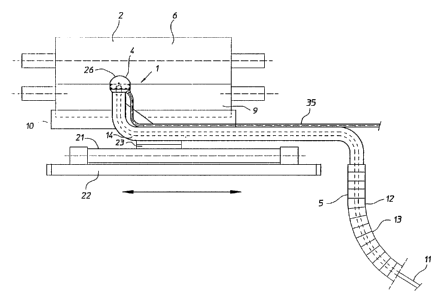
Figure 1 is a lateral view of a cleaning unit of the
apparatus according the invention, with a nozzle head
displaced from the centre of a pattern roll.
Figure 2 is an end view of the cleaning unit according to
Figure 1.
Figure 3 is a service unit of the apparatus according to
the invention, for serving the cleaning unit according to
Figure 1.
Figure 4 is a perspective view of a nozzle head
substantially similar to that in Figure 1, but directed
towards the centre of a pattern roll to be reconditioned.
Figure 5 is an end view of the nozzle head and pattern
roll according to Figure 4.
Figure 6 is a perspective view of a nozzle head arranged
to clean a flat section of an object running over at
least two rolls.
With reference to Figures 1 and 2 it is shown therein
schematically a cleaning unit 1 of an apparatus according
to the invention for cleaning a surface 2 in movement,
whereas Figure 3 shows schematically a service unit 3 of
the apparatus to serve the cleaning unit 1. The cleaning
unit 1 comprises a nozzle head 4 connected to the service
unit via pipe means 5. In the embodiment shown the moving
surface 2 to be cleaned consists of the shell surface of
a rotating pattern roll 6 which forms a nip with a
counter roll 7, a paper web 8 passing through the nip
where printing is effected on the side in contact with
the pattern roll 6. Ink is supplied to the pattern roll 6
2~.~fl.~~1
WO 94/12349 PCT/SE93/01012
by an inking feed roller 9, the shell surface of which
passes through an ink solution in a trough 10.
The pipe means 5 comprise a supply pipe 11 for fresh
5 treating liquid, e.g. water or some other solvent, and an
evacuation pipe 12 for spent liquid which now contains
impurities, i.e. ink and loose fibres from the paper web
in the case described, as well as dirt and dust. The
evacuation pipe 12 is provided with an intermediate
portion 13 which is flexible, and end portions 14, 15 at
the two units 1, 3, which are rigid and bent in suitable
manner. The supply pipe 11 for fresh treating liquid
extends inside the evacuation pipe 12 and may consist of
a hose.
The service unit 3 includes a tank 16 containing fresh
treating liquid in one or more containers, and equipment
for cleaning used liquid containing impurities. Above the
tank 16 is a vacuum pump 17 to which the evacuation pipe
12 is connected by its end portion 15, the vacuum pump 17
being connected to said cleaning equipment in the tank 16
by means of a return pipe 18. An air filter 19 is
connected to the cleaning equipment to let out air
separated from the liquid containing impurities and
supplied at the cleaning unit 1 to serve as carrier for
the liquid used and impurities released. A high-pressure
pump 20 arranged above the tank 16 is connected to the
clean treating liquid in the tank 16. The hose 11 is
connected to the high-pressure pump 20 which is thus
arranged to feed clean treating liquid to the nozzle head
4 via the hose 11.
The nozzle head 4 can be moved parallel to the shaft of
the pattern roll 6 in a to and fro movement effected by
an actuator 21 in the form of a pneumatic or hydraulic
cylinder rigidly mounted on a stand 22 (not shown in
Figure 2). The plunger in the cylinder 21 is rigidly
WO 94112349 ~ ~ ~ ~ ~ ~ PCT/SE93/01012
6
connected to the bent, rigid end portion 14 of the
evacuation pipe 12 via a connection piece 23. The nozzle
head 4 is rigidly connected to the end portion 14 so that
the nozzle head 4 is guided along the shell surface 2 at
a constant distance therefrom to ensure a gap 34, as will
be explained further below. In the embodiment according
to Figures 1 and 2 the centre line of the nozzle head 4
is somewhat displaced from the centre of the pattern roll
6, whereas the nozzle head 4 in the embodiment according
to Figures 4 and 5 is directed exactly towards the
centre.
The nozzle head 4 (see Figures 4 and 5) includes a
housing 25 consisting of a casing with circular cross
section, and a jet nozzle 24 arranged in the casing 25 in
the immediate vicinity of the centre line of the casing.
The casing 25, which is preferably cylindrical, itself
forms an elongate suction nozzle 26 which terminates in
an orifice edge 29 surrounding an opening 39 free from
mechanical parts. The suction nozzle 26 contains a
chamber 32 comprising said opening 39 and is arranged
spaced from the shell surface 2 to form a circumferential
gap 34 between the shell surface 22 and orifice edge 29.
The jet nozzle 24 is arranged in the chamber 32 of the
casing, spaced axially from the opening 39, to emit a jet
40 of treating liquid producing a predetermined treatment
area 41 on the shell surface 2. A holder 27 is mounted
inside the casing 25, the location of which may be fixed
but is preferably adjustable to different positions with
the aid of a suitable adjustment means (not shown). The
holder 27 carries the jet nozzle 24, the orifice 28 of
which is located centrally in the casing 25. The position
. of the jet nozzle 24 in relation to the holder 27 may be
fixed or adjustable. The hose 11 is connected to a
central, axial aperture 30 in the holder 27, this
aperture 30 communicating with the jet nozzle 24. The
holder 27 is also provided with a plurality of
2~~~~~.1
' WO 94/12349 PCT/SE93/01012
7
peripheral, axial through-holes 31 through which the
evacuation pipe 12 communicates openly with the chamber
32 of the suction nozzle 26. The front end of the suction
nozzle 26 is shaped with a contour to fit the curvature
of the pattern roll 6 to~produce said gap 34. This
contour thus varies in shape depending on the alignment
of the suction nozzle 26 in relation to the centre of the
pattern roll, as illustrated by the two embodiments in
Figure 2 and Figure 5.
During linear displacement of the nozzle head 4 this is
guided by its suspension in the cylinder 21 so that the
size of the gap 34 is kept constant all the time.
According to the present invention the jet nozzle 24 is
arranged spaced from the cylindrical inner side 42 of the
suction nozzle 26 so that a free, circumferential passage
43 of the chamber 32 is formed between the inner side 42
and the jet nozzle 24. This passage 43 thus communicates
directly with the evacuation pipe 12 via the axial
apertures 31 in the holder 27.
According to the present invention the nozzle head 4 also
includes means 44 for a controlled supply of compressed
air to the chamber 32 via said gap 34 in order to
encounter and carry with it liquid deflected from the
surface 2 and material released from the shell surface 2
towards and through said passage 43. The supply means 44
for compressed air includes a pipe 35 and a distributor
connected to the pipe 35 for forced supply of compressed
air to the suction nozzle 26 close to the orifice edge 29
so that a strong flow of air is introduced into the
chamber 32 through the gap 34. The increased air flow
also results in favourable drying of the shell surface 2.
The compressed air may be supplied all around the gap 34
or only to certain parts of it, particularly downstream
of the orifice edge 29 in that case when the pattern roll
WO 94/12349 PCT/SE93/01012
8
6 or other object is rotating with such high speed that
its surface 2 carries with it a layer of air into the
chamber 32 through the gap 34 upstream of the orifice
edge 29, seen in the direction of rotation of the pattern
roll. The compressed air jets are thus aligned so that
they hit the shell surface 2 upon passage through the gap
34. A suitable alignment is thus about 40-90° in relation
to the outer surface of the casing 25. The distributor is
not shown in Figure 4 but is generally intimated by
arrows 33 to illustrate the distribution of the
compressed air downstream of the orifice edge 29. In
Figure 5 the distributor is shown in the form of an
endless pipe 37 extending around the entire suction
nozzle 26, close to the orifice edge 29, and provided
with a plurality of apertures 38 facing towards the gap
34 so that jets 45 of compressed air are forced into the
chamber 32 via the gap 34 at the same time as hitting the
shell surface 2 to dry it.
Figure 6 shows a nozzle head 4 similar to that in Figure
4 but modified to treat the flat surface 2 of a moving
wire or felt 36 in a paper machine in operation. The only
difference is that the orifice edge 29 of the casing 25
has been made flat instead of concave so that the orifice
edge 29 lies in a plane perpendicular to the central axis
of the nozzle head 4. A nozzle head of the type shown in
Figure 4, i.e. with an inwardly curving orifice edge 29,
can also be used to great advantage for cleaning a wire
or felt 36 by being mounted next to a curved surface of
the wire or felt, i.e. where it runs over a roll. A
greatly improved result is obtained since the wire or
felt exposes inner portions as it passes and is bent '
around a roll and the liquid jet 40 also acts on these
inner portions of the surface 2.
The term "impurities" refers to all material that,
particularly during operation, adheres to the surface 2
2~.~~al~
~WO 94112349 PCT/SE93/01012
9
of the object 6 and includes not only particles such as
dust and dirt from the surroundings and fibres from the
material web, e.g. paper web, in contact with the moving
surface, but also such material which, with the aid of_
the moving surface, is to be applied on a passing web of
material, or which is already on the web of material.
The liquid used for cleaning the surface 2 of the object
6 may be any suitable liquid whatsoever, depending on the
nature of the moving surface to be cleaned. The liquid
may be at ambient temperature or increased temperature.
It is totally free from solid particles since these might
damage the surface 2 of the object 6. In most cases it is
sufficient to use fresh water.
The apparatus also includes a control unit (not shown)
which influences the actuator 21 and controls the
movements of the nozzle head 4 to and fro in relation to
the velocity of the roll, wire, felt or other object 6 so
that the entire surface 2 is treated and cleaned within a
certain period of time. The rate of feed of the nozzle
head 4 across the direction of movement of the object is
selected in proportion to the effective dimension of the
treatment area 41 (transversely over the object 6). If
the latter is for instance 10 mm, the feed rate may be at
most 8 mm per revolution. With the aid of a step motor,
for instance, or some other suitable actuator, the
control unit can be programmed to control the nozzle head
4 to clean only, or more frequently, specific parts of a
roll, for instance.
If desired the apparatus may be provided with one or more
additional nozzle heads 4 in order to increase its
capacity.
The shape of the treatment area 41, determined by the
shape of the opening 28, may be oblong with little width,
WO 94/12349 ~ ~ ~ PCT/SE93/01012
which is preferred, or oval or circular. The largest
effective dimension of the treatment area 41 is generally
perpendicular to the direction of movement of the object
6 and is suitably 1-50 mm, preferably 5-10 mm, depending
5 on prevailing operating conditions. The diverging shape
of the jet 40 then encompasses an angle of about 5-50°.
The larger the angle the greater must be the shortest
distance of the treatment area 41 to the gap 34. If the
angle is 45°, therefore, this distance is at least about
10 15-20 mm.
The treating liquid supplied to the jet nozzle 24 has a
pressure of 50-500 bar, preferably 150-300 bar, depending
on the prevailing operating conditions. The liquid jet 40
thus hits the object 6 at a very high pressure and the
liquid jet 40 thus has a mechanical effect in that it
breaks up impurities on the object and knocks them loose,
thereafter taking the impurities with it. At the same
time the surface of the object is washed with treating
liquid when the jet 40 hits the surface, and at least
some of the impurities may dissolve immediately in the
liquid or during evacuation.
The quantity of liquid used is suitably 0.12-5 1/min,
preferably 0.5-1.5 1/min, for each nozzle head 4,
depending on the prevailing operating conditions.
The size of the gap 34, i.e. the distance between the
orifice edge 29 and the surface 2 of the object 6 is
suitably 1-5 mm, preferably 1.5-3.0 mm, depending on the
prevailing operating conditions.
The distance of the jet nozzle 24 to the surface 2 of the
object 6 is suitably 2-20 mm, preferably 2-5 mm,
depending on the prevailing operating conditions.
However, it should never be less than the size of the gap
34 in any operating case.
WO 94/12349 ~ ~ ~ PCT/SE93/01012
11
The limit of the treatment area 41 produced by the liquid
jet 40 is located at a distance from the gap 34 to
prevent liquid and impurities squirting out through the
gap 34 and also to enable compressed air to be forced in
through the gap 34 so that a flow of air will entirely
surround the liquid jet 40 and be deflected up towards
and through the passage 43 to serve as transport air for
the used deflected liquid and impurities. Said distance
is at least 10 mm.
In order to ensure a uniform flow of liquid, air and
impurities past the jet nozzle 24, as well as an
efficient flow of air away from the gap 34 into the
chamber 32, it is also important for the jet nozzle 24 to
be arranged in or close to the centre of the casing 25.
The jet nozzle 24 or just its orifice 28 can be adjusted
so that the liquid jet 40 forms an angle of 0-45° with
the centre line of the casing 25, the liquid jet 40 thus
forming an angle of less than 90° with the tangent at the
point where the liquid jet impacts the roll, seen against
the direction of rotation. Depending on the alignment, of
the jet nozzle 24, the centre of the treatment area 41
can be moved from 0 to 20 mm towards the upstream part of
the gap 34 in order to compensate for the speed of
rotation of the roll.
It will be understood that in the evacuation pipe 12 and
associated chamber 32 the subpressure is regulated to a
level at which the necessary suction force is created in
order to evacuate all liquid, air and impurities
backwards from the suction nozzle 26 and through the
evacuation pipe 12 without any liquid, air or impurities
penetrating out through the gap 34.
Thus, the invention provides an efficient apparatus for
cleaning rotating rolls and wires, for instance, without
WO 94/12349 ~ ~ ~ PCT/SE93/01012
12
the aid of mechanical construction elements working on
the surface. The invention enables rolls to be cleaned
with liquid jets at extremely high pressure while still
obtaining a dry surface. The apparatus thus provides a
combined cleaning and drying effect.