Note: Descriptions are shown in the official language in which they were submitted.
2~.5f~~9
- 1 -
C~1TRIFUGAL PUI~
This invention relates to a centrifugal pump.
Centrifugal pumps normally have to have some form of rotary
seal at the point where the rotating shaft carrying an
impeller passes out through a stationary casing.
The rotary seal can be in the form of a device known as a
mechanical seal and mechanical seals require a certain
environment in order to operate successfully.
For example, it is important to maintain sufficient
pressure in the fluid surrounding the mechanical seal in
order to avoid local boiling at the faces of the seal,
since boiling can damage the seal and reduce life. Also,
it is important to avoid suspended solids in the
surrounding fluid since such solids can cause accelerated
wear of the seal faces. Finally, prior to start-up, any
gas needs to be vented from the immediate vicinity of the
seal, i.e. in the so-called seal chamber.
Most existing designs of process pumps achieve maintenance
of sufficient pressure in the surrounding fluid by
provision of back-pressure clearances. Flushing flow of
fluid is arranged to pass from a pump discharge of the
impeller back to a suction side of the impeller via such a
clearance. This creates higher pressure in and around the
mechanical seal. The device to cause this to happen is
often referred to as a throat bushing, which a.s fixed, the
clearance being between the inner cylindrical face of the
throat bushing and the cylindrical face of the rotating
shaft.
- 2 -
A negative effect of known throat bushes is that while
sufficient pressure is maintained in the surrounding fluid,
suspended solids in the surrounding fluid are not removed
and a separate vent hole must be provided to vent any gas
prior to start-up. However, the cross-sectional area of
the vent hole can be significant relative to the throat
bush clearance. This reduces the back-pressure and also
encourages wasteful extra leakage.
Any solids flowing into the seal chamber from the impeller
discharge tend to get centrifuged to the walls. These
solids find it difficult to escape through the throat bush
clearance since they have to move against the centrifugal
force field. Accordingly, there is a tendency for solids
to accumulate at the seal chamber walls but whatever solids
do escape could damage the shaft in the vicinity of the
clearance.
Finally, it is often necessary to dismantle the pump in .
order to drain the seal chamber fully.
According to the present invention, there is provided a
centrifugal pump including a rotating shaft and an impeller
on the shaft, the impeller having an internal fluid flow
path with a fluid inlet substantially adjacent said shaft,
said fluid flow path extending therefrom in an increasingly
radial direction to terminate at a fluid pump discharge
outlet at the tip of the impeller and there being a
flushing and cooling fluid flow path extending from the
region of said pump discharge outlet, through a fixed part
of the pump, into a seal chamber containing a seal for said
shaft, through a clearance between a hub of the impeller
and said fixed part, and returning through a wall of said
impeller to a suction side of said internal fluid flow
path, wherein said clearance is located radially outwardly
2~.5fl~~3
- 3 -
of and remote from said shaft, thereby to act, in use, as
a vent and to clear debris from said seal chamber.
The clearance may be located between an annular case wear
ring, which protrudes from and is attached to a casing for
the pump, and the hub of the impeller, the annular case
wear ring and casing constituting said fixed part.
The hub of the impeller may be provided with a renewable
wear part surrounding an outer annular face of the case
wear ring, there being a second clearance between the
renewable wear part and said outer annular face.
The impeller hub may be provided with a second renewable
wear part surrounding an inner annular surface of the case
wear ring, said second renewable wear part defining with
the case wear ring the firstmentioned clearance.
In addition or instead, a throat bush constituting a
further renewable wear part can be mounted on the shaft
adjacent the hub of the impeller and extending towards the
inner annular face of the case wear ring, the
firstmentioned clearance in this case being defined by the
gap between the inner cylindrical face of the throat bush
and the case wear ring.
For a better understanding of the invention and to show how
the same may be carried into effect, reference will now be
made, by way of example, to the accompanying drawings, in
which:
Figures 1 to 4 each show, in diagrammatic cross-section,
different embodiments of a centrifugal pump, each Figure
only showing part of the pump.
- 4 -
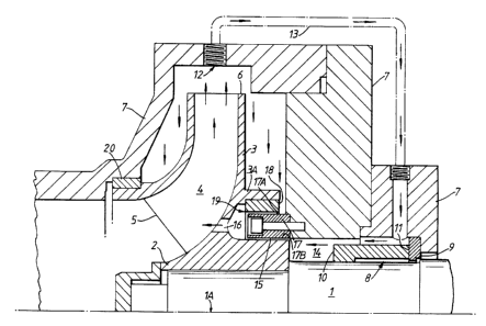
Referring to the drawings, Figure 1 is a diagrammatic
sectional view of part of a centrifugal pump with a central
axis lA defined by a rotating shaft 1. A hub 2 of a
centrifugal impeller 3 is mounted on the shaft 1, the
impeller 3 having an internal fluid flow path 4 which
extends in known manner initially in a direction
substantially parallel to the shaft 1 at an inlet or
suction side 5 and then turns into an increasingly
outwardly radial direction to terminate at a fluid pump
discharge outlet at the tip 6 of the impeller.
The shaft 1 and impeller 3 are mounted within a stationary
casing 7 comprising a plurality of casing parts and a
so-called mechanical seal 8 is provided at the point where
the shaft 1 passes out through the casing 7. The seal 8
basically comprises a fixed rubbing face 9 attached to the
casing 7 and a rotary member 10 which is fixed on the shaft
1 and which has a rubbing face 11 which is urged by
resilient means (not shown) into sealing contact with the
fixed face 9. The two faces 9 and 11 in contact with one
another provide the required seal.
In order to cool the rubbing, sealing faces 9 and 11, a
fluid flow is arranged in the region of those faces.
As indicated by the flow arrows in Figure 1, the main fluid
flow is caused by centrifugal force to flow from the
suction side at the inlet end 5 of the impeller 4, out of
the discharge end at the tip 6 of the impeller. The major
part of the flow is then caused by the internal profile of
the casing 7 to follow an onwards flow path. A port 12 is
provided in the wall of the casing 7 opposite, i.e. facing,
the discharge end of the impeller 4 and a conduit 13
extends from the port 12 and opens into another part of the
casing adjacent the mechanical seal 8.
21~~~~3
- 5 -
The mechanical seal 8 is mounted in a seal chamber 14 and
the fluid flow path through the conduit 13 flows over the
seal 8, through the seal chamber 14 and is then arranged to
pass through a clearance 15 between the hub 2 of the
impeller 3 and return through a port 16 in the wall of the
impeller 3 to the suction side of the impeller. The
clearance 15 provides the required back-pressure to achieve
sufficient pressure in the surrounding fluid for the
cooling flow path to function.
In the embodiment of Figure 1, the clearance 15 is
constituted by the outer cylindrical face of the hub 2 of
the impeller 3 and the inner annular face 17B of an annular
case wear ring 17, which protrudes from and is attached to
the casing 7.
It will be seen that the clearance 15 is located radially
outwardly of and remote from the shaft 1 and is so located
that the upstream end of it, i.e. the end leading from the
seal chamber 14 is substantially adjacent the inner
periphery of the casing 7 which defines the radially outer
boundary of the seal chamber 14.
Figure 1 also shows a renewable wear part 18 which is fixed
to a flange 3A on the impeller 3, the wear part 8
surrounding an annular outer face 17A of the case wear ring
17, thereby defining a second clearance 19 between the wear
part 18 and the outer annular face 17A. Accordingly, the
fluid flow from the discharge end of the impeller is also
caused to flow through this clearance to join the flow
through the clearance 15 and thence through the port 16.
With this construction, the seal chamber 14 is able to be
self-vented upon start-up, solids can be automatically
centrifuged from the chamber because of the radially
2~~~2~3
- 6 -
outward location of the clearance 15 and the seal chamber
can also be fully drained.
A further wear part 20 is provided between the wall of the
casing 7 and the inlet or suction end 5 of the impeller.
In the embodiment of Figure 2, a modification is shown,
wherein a further removable wear part 21 is provided on the
hub 2 of the impeller, this wear part 21 having an outer
annular surface which faces and surrounds the inner annular
surface 17B of the annular case wear ring 17 so that the
clearance 15 is defined between the renewable wear part 21
and the annular case wear ring 17.
In the embodiment shown in Figure 3, a renewable, annular
throat bush 22 is fitted on the shaft 1 as an extension of
the hub 2 of the impeller, an outer cylindrical face of the
throat bush 22 defining the clearance 15.
The renewable wear part 18 is relocated so that it also
faces the inner annular surface 17B of the annular case
wear ring 17 and it will be seen that the fluid flow path
therefore runs as an extended bore 23 through the hub 2 of
the impeller 3 parallel to the axis of the shaft 1.
The embodiment shown in Figure 4 is a combination of the
embodiments of Figures 1 and 3, wherein the throat bush 22
is provided but the renewable wear part 18 is retained on
the flange 3A of the impeller to face the outer annular
surface of the annular case wear ring 17.
In all cases, the clearance 15 is arranged aligned with the
inner annular profile of the casing 7 where it defines the
outer wall of the seal chamber 14 in order to assist in the
clearance of debris by centrifugal force from the chamber
215023
14 whilst obviating the need for a separate vent hole and
whilst enabling the seal 8 to be cooled. There is
basically a smooth path between the outer diameter of the
seal chamber 14 and the clearance 15 to facilitate the
smooth passage of debris out of the chamber 14, which works
as a result of the centrifugal force and the fluid flow.
In the embodiments shown, the pumps have shafts 1 with
generally horizontal axes lA. In these cases, the
alignment of the clearances 15 and uppermost regions of the
seal chambers 14 allow natural self-venting. However, the
shafts 1 could be in pumps where the shafts are other than
horizontal, e.g. vertical, in which case other arrangements
may need to be made for venting the seal chamber.
With the present constructions, it should also not be
necessary to dismantle the pump to drain the seal chamber
since the effect of the centrifugal action on a short "dry"
run should be sufficient to clear the seal chamber.
It will be appreciated that with the present constructions,
any wear that takes place will occur on renewable surfaces.