Note: Descriptions are shown in the official language in which they were submitted.
2150~40
BACKLIGHT DEVICE FOR DISPLAY APPARATUS
FIELD OF THE INVENTION AND RELATED ART
The present invention relates to a backlight
device for display apparatus, such as those for
computers, word processors, television receivers and
navigation systems, and view finders for video
cameras.
Backlight devices or display apparatus may be
classified into the direct backing-type and the edge
(or H-arrangement)-type. Examples of the former type
have been disclosed in Japanese Laid-Open Patent
Appln. (JP-A) 2-39118 and JP-A 6-18873, and examples
of the latter type have been disclosed in JP-A 63-
13202, JP-A 4-71105, JP-A 5-281541 and JP-A 5-323318.
A representative example of the H-arrangement-type
backlight device for a transmission-type liquid
crystal panel has been proposed by JP-A 57-128383 and
Figure 21 is a schematic illustration thereof.
Referring to Figure 21, a backlight device Bo
includes a fluorescent lamp l as a light source and a
reflector 2 disposed to surround the fluorescent lamp
l. Extending sidewards from the fluorescent lamp 1 is
disposed a light-guide member 3 of a thick transparent
plate of, e.g., acrylic resin. Behind the light-
guide member 3, light-scattering layers 5 are disposed
in a prescribed areal proportion. Light issued from
21aO3~
the fluorescent lamp 1 and entering the light-guide
member 3 is scattered by the scattering layers 5 and
issued from the front face of the light-guide member 3
to illuminate a liquid crystal panel (not shown) at a
uniform illuminance.
In the above-mentioned backlight device, the
light-guide member 3 is composed of, e.g., an acrylic
resin, and is therefore heavy, so that the backlight
device becomes heavy and suffers from inferior
conveyability. Particularly, in recent years, a
liquid crystal panel size is enlarged so that the
backlight is also enlarged. Accordingly, the light-
guide member is thick and enlarged in area, so that
the above-mentioned difficulty is promoted.
For the above reason, a backlight device
using no light-guide member has been proposed as in
JP-A 5-323318. The backlight device has resulted in a
poor planar illumination uniformity and is unsuitable
for a large area display apparatus having a diagonal
size of 15 inches or larger. Further, the backlight
device is required have a backing reflector shaped in
a parabora curved surface and requires a substantial
production cost.
JP-A 5-281541 also discloses a backlight
device capable of dispensing with a light-guide
member, but the device also suffers from a poor planar
illumination uniformity, which becomes noticeable in a
21~0340
large-area display apparatus having a diagonal display
area size of 15 inches or larger.
On the other hand, direct backing-type
backlight devices generally require a large thickness
behind display apparatus and are unsuitable for flat
panel displays. Particularly, uniform illumination
light cannot be attained for large area display
apparatus unless a large number of light sources
(fluorescent lamps) are used. Anyway, direct backing-
type backlight devices are liable to be complicatedand expensive for a larger size and are believed to be
unsuitable for flat panel-type display apparatus of an
increasingly large display area.
Accordingly, it has been desired to develop
an improved edge-type or H-(arrangement-)type
backlight device, instead of a direct backing-type
device, through elimination of various difficulties of
the edge-type backlight device.
SUMMARY OF THE INVENTION
An object of the present invention is to
provide a backlight device for display apparatus
capable of issuing uniform illumination light without
using a light-guide member occupying a substantial
z5 part of the total weight of such a backlight device,
when used.
Another object of the present invention is to
21~03~0
provide a backlight device for display apparatus,
which is light and excellent in portability.
Another object of the present invention is to
provide a backlight device for display apparatus
capable of providing improved viewing angle
characteristic and moire-freeness.
Another object of the present invention is to
provide a backlight device for display apparatus,
capable of issuing uniform planar illumination light
even for a large display area having a diagonal size
of 15 inches or larger.
A further object of the present invention is
to provide a backlight device for display apparatus,
capable of issuing uniform planar illumination light
even at a relatively low accuracy of designing of a
reflection layer and a disposition density thereof.
A still further object of the present
invention is to provide a backlight device for display
apparatus capable of preventing an adverse effect of
radiation heat from a light source to a display
device.
Sill another object of the present invention
is to provide an inexpensive but reliable backlight
device for display apparatus.
A yet further object of the present invention
is to provide a backlight device for display apparatus
capable issuing illumination light having uniform
21503~
spectral characteristic at the illuminated surface.
According to the present invention
accomplished in view of the above-mentioned
circumstances, there is provided a backlight device,
comprising: reflection means for reflecting light, a
transmission member disposed opposite to the
reflection means so as to form a space from the
reflection means, and a light source disposed to emit
light into the space, so that light issued from the
light source into the space is reflected by the
reflection means and transmitted through the
transmission member. In this instance, it is
preferred that the transmission member is provided
with a reflection layer having a multitude of
apertures, so that the light issued from the light
source into the space is repetitively reflected by the
reflection means and the reflection layer to be leaked
outwards through the transmission member out of the
apertures. It is also preferred that the apertures
are arranged to have an area per unit region of the
transmission member, which area increases with an
increase in distance from the light source. It is
further preferred that the reflection means is
provided with a scattering layer for scattering and
reflecting light on a face of the reflection means
opposite to the reflection layer. It is also
preferred that the scattering layer is provided with a
21S03 l~l
multitude of apertures arranged to have an area per
unit region of the scattering layer, which area
decreases with an increase in distance from the light
source. It is further preferred that the backlight
device further includes a polarization beam splitter
supported on the transmission member for selectively
transmitting a p-polarization component and
reflecting an s-polarization component, and a quarter
wave plate disposed on the reflection means and
opposite to the transmission member for causing
conversion between the p-polarization component and
the s-polarization component, whereby light emitted
from the light source into the space is reflected
between the polarization beam splitter layer and the
reflection means so that the p-polarization component
of the emitted light is selectively leaked outwards
through the transmission member.
According to another aspect of the present
invention, there is provided a backlight device,
comprising:
a first reflection means for reflecting
light,
a second reflection means disposed opposite
to the first reflection means so as to form a space
therebetween and provided with apertures having a
prescribed aperture ratio distribution,
at least one linear light source disposed to
21~0340
emit light into the space, and
at least one sheet of prism means having a
multitude of prism ridges extending parallel with the
linear light source,
so that light emitted from the linear light
source is repetitively reflected between the first and
second reflection means, and a portion of the light is
transmitted through the second reflection means and
the prism means to be emitted in a direction
~0 deflected toward a normal to the prism means.
According to the present invention, there is
further provided a display apparatus, comprising:
a backlight device as described above,
a backlight drive means for driving the
~5 backlight device,
a display device, particularly a liquid
crystal display device, illuminated by the backlight
device, and
a drive means for driving the display device.
These and other objects, features and
advantages of the present invention will become more
apparent upon a consideration of the following
description of the preferred embodiments of the
present invention taken in conjunction with the
accompanying drawings, wherein like parts are denoted
by like reference numerals.
215034~
BRIEF DESCRIPTION OF THE DRAWINGS
Figure 1 is a schematic exploded illustration
of a backlight device according to the present
invention.
Figures 2 - 5 are sectional views for
illustrating first to fourth embodiments,
respectively, of backlight device according to the
invention.
Figures 6 and 7 are graphs showing an
aperture ratio distribution in a reflection layer and
a luminance distribution, respectively, of a fifth
embodiment of the backlight device according to the
invention.
Figure 8 is a sectional view for illustrating
a sixth embodiment of the backlight device according
to the invention.
Figure 9 is a schematic exploded illustration
of the sixth embodiment of the backlight device
according to the invention.
Figure lO is a graph showing an aperture
ratio distribution of a prism sheet in the sixth
embodiment of the backlight device according to the
invention.
Figures llA and llB are graphs showing
viewing angle-dependence of luminance in cases of
using one prism sheet and two prism sheets,
respectively, in the sixth embodiment of the backlight
2 1 ~ 0 3 A O
device.
Figure 12 is a graph showing a planar
luminance distribution in the sixth embodiment of the
backlight device.
Figures 13 and 14 are sectional views for
illustrating 7th and 8th embodiments of the backlight
device according to the invention.
Figure 15 is a graph showing a viewing angle-
dependence of luminance regarding the effect of the
8th embodiment.
Figure 16 is a sectional view for
illustrating a position of diffusion means.
Figures 17 and 18 are sectional views for
illustrating 9th and 10th embodiments of the backlight
device according to the invention.
Figures 19 and 20 are respectively a block
diagram of a display apparatus using a backlight
device according to the invention.
Figure 21 is a schematic sectional view of a
conventional backlight device.
Figures 22 and 23 are respectively a plan
view showing a preferred reflection layer pattern.
DESCRIPTION OF THE PREFERRED EMBODIMENTS
A preferred embodiment of the backlight
device according to the present invention will be
described with reference to Figure 1, an exploded
2150340
- 1 o -
perspective view thereof.
Referring to Figure l, a transmission-type
display device P is illuminated by a backlight device
according to the invention including light sources l,
reflectors 2, a reflection means lO and a transmission
member 11 having a pattern of reflection layer.
The light sources are disposed outside the
display device P to form an edge-type or H(-
arrangement)-type backlight device. In other words,
when the light light sources l are constituted by a
pair of lamps, the lamps are disposed with a spacing
of at least M which is a lateral length of the display
device P.
The light source l may be any light source
having a spectral distribution desired by the display
device P. Specific examples thereof may include LEDs,
halogen lamps, xenone lamps and white fluorescent
lamps. Particularly, for a display device having
three types of pixels of red (R), green (G) and blue
(B), it is preferred to use a three-wavelength type
white fluorescent lamp having a spectral
characteristic of providing emission peaks in the
regions of R, G and B, respectively.
The reflectors 2 and reflecting means lO may
for example comprise a metal member having a
reflecting inner surface or a light-absorbing or
light-transmissive substrate coated with a reflective
215Q3~Q
material forming an inner surface.
The transmission member ll may comprise a
light-transmissive substrate surface-coated with
pattern of reflection layer. The reflection layer
pattern may preferably have apertures (portions free
from the reflection layer) occupying an areal ratio
(i.e., aperture ratio) which increases with an
increase in distance in X-direction from a light
source 1. In the embodiment of Figure l having two
light sources 1 at both ends in the X-direction, the
aperture ratio is determined based on distances of 0
to M/2 from the light sources at the left and right
ends.
The reflection layer may have a pattern of a
multitude of reflective portions various shapes, such
as circles ellipses, squares, rectangles, lozenges,
parallelograms, trapezoids and starts. Alternatively,
as a negative or complementary pattern to the above-
mentioned reflective portions, the apertures can
assume various discrete shapes as descried above.
The display device P may suitably comprise a
liquid crystal device, examples of which may include:
STN-type and DSTN-type liquid crystal devices using
nematic liquid crystals; active matrix-type liquid
crystal devices using thin-film transistors or MIM-
elements; and ferroelectric liquid crystal devices and
anti-ferroelectric liquid crystal devices using chiral
21503a~
smectic liquid crystals.
In the case of a liquid crystal device using
a chiral smectic liquid crystal, there has been
reported a liquid crystal molecular movement resulting
in a change in liquid crystal layer thickness and
causing a yellow-tinging or a display area (U.S.
Patent No. 5,381,256). Accordingly, if the spectral
characteristic of illumination light is changed to
have a yellowish tint, the yellow tinging is liable to
be enhanced. For this reason, it is preferred to use
a backlight device of the present invention free from
spectral characteristic change in combination with a
chiral smectic liquid crystal device for obviating the
above difficulty.
In addition to the structure shown in Figure
1, the backlight device according to the present
invention may preferably further comprise a prism
sheet so as to have the direction of light issuance
therefrom approach a planar normal. In this instance,
it is particularly preferred to use a plurality of
prism sheets so that their convex surfaces are
directed toward a display device side as will be
described with reference to Figure 8 or use a prism
sheet disposed to have its convex surface directed
toward a reflecting means lO as will be described with
reference to Figure 14. Further, it is also possible
to provide the reflecting means with a reflecting
~laO3~0
surface shaped so as to reduce the number of
reflections thereat as will be described with
reference to Figures 17 and 18, while a shaping step
may be additionally required thereby.
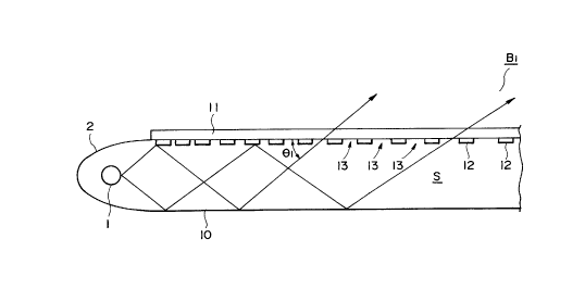
An embodiment of backlight device Bl shown in
Figure 2 is provided with a rear reflecting plate
(reflection means) 10 composed of an aluminum plate.
The rear reflecting plate 10 has a mirror-finished
surface so as to reflect light incident thereto. The
reflecting plate is integrally formed with reflectors
2 having a concave surface composed also of an
aluminum plate. In front of the rear reflecting plate
10, a front transmission plate (transmission member)
11 of a thin transparent acrylic resin plate is
disposed with a spacing from and in parallel with the
reflecting plate lO, so that a space S is defined by
the rear reflecting plate lO and the front
transmission plate 11. At the lateral ends (e.g., the
parts surrounded by the reflectors 2), three
wavelength-type fluorescent lamps 1 as linear light
sources are disposed so that light emitted therefrom
enters the space S directly or indirectly after
reflection by the reflector 2.
On the other hand, on the lower surface
(i.e., opposite to the rear reflection plate 10) of
the front transmission plate 11, a reflection layer 12
of, e.g., vapor-deposited aluminum is disposed in a
2150340
pattern of a mesh or various discrete shapes as
described above to form a multitude of apertures 13,
out of which light is allowed to leak out through the
front transmission plate 11.
In this embodiment, the apertures 13 are
arranged to have an aperture ratio k(x), i.e., a ratio
of an area occupied by the apertures 13 per unit
region of the front transmission plate 11 at a
position disposed at a distance x from the nearest
fluorescent lamp 1, which aperture ratio increases
with an increase in the distance x, e.g., in a
relationship of l-k(x) = a/x, wherein a is a
proportional constant.
Above the front transmission plate ll is
disposed a transmission-type liquid crystal panel (not
shown) so that the liquid crystal panel is illuminated
with the light issued from the backlight device Bl.
When the fluorescent lamp l is turned on,
light emitted from the fluorescent lamp enters the
space S directly or after being reflected by the
reflector 2. The light having entered the space is
repetitively reflected by the reflecting layer 12 and
the rear reflection plate lO disposed opposite to each
other, so that the space S functions as a light-guide
space. Then, a portion of the light is leaked out
through the apertures 13 of the reflection layer 12
and the transparent plate 11 to illuminate a liquid
~ -15~
crystal panel (not shown) disposed above the plate 11.
The angle (denoted by "~1" in Figure 2) of
light incident to the transmission plate 11 becomes
smaller as the position leaves away from the
fluorescent lamp 1 so that leakage quantity of the
light becomes smaller in proportion to almost the
angle ~1 if the aperture ratio k is constant. In this
embodiment, however, the aperture ratio k(x) of the
reflection layer 12 is set to be larger as the
distance x increases, so that the leakage light
quantities at various positions become substantially
equal. As a result, the planar luminance distribution
of the leakage light (illumination light) from the
backlight device Bl becomes uniform to provide an
improved display quality to the liquid crystal panel.
In this embodiment, the light-guide member 3
(Figure 21) required in the conventional device is
omitted, so that the backlight device becomes lighter
in weight by that much and provides an improved
portability to even a large-area display apparatus.
A second embodiment of the backlight device
according to the present invention will now be
described with reference to Figure 3, wherein parts
identical to those shown in Figures 1 and 2 are
denoted by identical reference numerals and
descriptions thereof may be omitted.
In this embodiment, a front surface (opposite
B~-
.~
-16-
to a transmission plate 11 and a reflection layer 12)
of a rear reflection plate 10 is provided with a
scattering layer 20. The scattering layer 20 may be
composed of a printed layer of a white pigment, such
as barium sulfate, calcium carbonate or titanium oxide
and, likewise the reflection layer 12, may be formed
in a mesh pattern or a discrete dot pattern so as to
provide a multitude of apertures 21. The aperture
ratio kl(x) of the scattering layer 20 is set to be
smaller as the distance from the fluorescent lamp
increases, in contrast to the case of the reflection
layer 12.
When the fluorescent lamp 1 is turned on,
emitted light is repetitively reflected between the
rear reflecting plate 10 and the reflection layer 12,
and light incident to the scattering layer 20 is
reflected as scattered light. Then, the light having
repeated the reflection and scattering is leaked out
through the apertures 13 of the reflection layer 12.
In this embodiment, similarly as in the
previous embodiment, the aperture ratio k(x) of the
reflection layer 12 is set to be larger as the
distance x from the fluorescent lamp 1 becomes larger,
so that the leakage light quantities at various
positions become almost equal. As a result, the
leakage light (illumination light) from the backlight
device B2 is caused to have a uniform planar luminance
12
V ~
~17~ 4 ~
distribution, thereby providing an improved display
quality to the liquid crystal panel.
Further, in this embodiment, light in the
space S is scattered by the scattering layer 20 formed
on the surface of the rear reflecting plate 10. As a
result, even if the incident angle ~2 of light
incident to the scattering layer 20 is small, the
light scattered from the scattering layer 20 can enter
the front transparent plate 11 at a larger incident
angle 03, so that the incident angle 03 can be uniform
and less dependent on the distance from the
fluorescent lamp 1, and leakage light quantities at
various positions become almost uniform because of
such uniformized angle characteristic. Accordingly,
the planar luminance distribution of the leakage light
(illumination light) is uniformized to provide an
improved display quality to the liquid crystal panel.
In an H-type (or edge-type) backlight device
like this embodiment, the incident light angle ~2
becomes smaller as the position is left away from the
fluorescent lamp l. However, in this embodiment, the
aperture ratio kl(x) of the scattering layer is set to
be smaller so as to provide a larger occupation areal
ratio (l-kl(x)) of the scattering layer 20 as the
position is left away from the fluorescent lamp l.
As a result, light having a smaller incident angle ~2
is more frequently scattered. Then, the scattered
B~
21~0340
-18-
light is incident to the transmission plate 11 at a
larger incident angle ~3 to be more readily leaked out
through the apertures 13 of the reflection layer 2.
As a result, leakage light quantities at various
positions of the backlight device is uniformized, so
that the planar luminance distribution of the leakage
light (illumination light~ becomes uniformized to
provide an improved display quality. Thus, the
backlight device can exhibit an improved performance
for a larger area display apparatus.
A third embodiment of the backlight device
according to the present invention will now be
described with reference to Figure 4, wherein parts
identical to those shown in Figures 1 to 3 are denoted
by identical reference numerals and descriptions
thereof may be omitted.
In this embodiment, a front surface (upper
surface) of a rear reflection plate lO is provided
with a ~4 plate 30 for effecting plarization
conversion between an s-polarization component (light
component having an electric field component
perpendicular to the drawing sheet of Figure 4) and a
p-polarization component (light component having an
electric field component parallel to the drawing sheet
of Figure 4), and a lower surface of a front
transmission plate 11 is provided with a polarization
beam splitter layer 31 of an optical multi-layer film,
215~3~0
-19-
which allows the transmission of only the p-
polarization component and reflects the s-polarization
component. In this embodiment, a liquid crystal panel
(not shown) disposed above the plat 11 is designed to
receive the p-polarized light as illumination light.
When the fluorescent lamp 1 is turned on,
emitted light is repetitively reflected between the
rear reflecting plate 10 and the polarization beam
splitter layer 31, and a p-polarization component of
the light incident to the polarization beam splitter
layer 31 is transmitted through the layer 31 and the
front transmission plate 11 to be leaked outwards. On
the other hand, the remaining s-polarization component
is reflected by the polarization beam splitter layer
31 and then incident to and reflected by the rear
reflection plate 10 where the s-polarization is
converted to p-polarization because it passes twice
the ~/4 plate 30. The resultant p-polarization
component is transmitted through the polarization beam
splitter layer 31 and the front transmission plat 11
to be leaked outwards.
As the liquid crystal panel is designed to
receive a p-polarized light in this embodiment, the
illumination efficiency of the backlight device can be
remarkably improved.
Next, a fourth embodiment of the backlight
device according to the present invention will be
21~0~4~
-20-
described with reference to Figure 5 wherein parts
identical to those shown in Figure 4 are denoted by
identical reference numerals.
In this embodiment, a front transmission
plate 11 is composed of a transparent glass plate and
the front surface of the front transmission plate 11
is provided with a reflection layer 12. Further,
between a rear reflection plate 10 and a ~4 plate 30,
a scattering layer 20 is disposed. The reflection
layer 12 is formed in a dot pattern or a mesh pattern
so as to have an aperture ratio k(x~ increasing with
an increase in distance from the fluorescent lamp 1
similarly as in the first embodiment, and the
scattering layer 20 is formed in a dot or mesh pattern
so as to provide a prescribed aperture ratio kl(x)
similarly as in the second embodiment.
When the fluorescent lamp 1 is turned on, an
s-polarization component is reflected by a
polarization beam splitter layer 31 and is then
reflected by a rear reflection plate 10 where it is
converted into a p-polarization component. On the
other hand, a p-polarization component is transmitted
through the polarization beam splitter 31, a portion
thereof is leaked out of the apertures 13 to
illuminate a liquid crystal panel (not shown) disposed
above, and the remaining portion thereof is reflected
by the reflection layer 12 to enter the space S again.
' -21~ 4 ~
The portion of the p-polarization component reflected
by the reflection layer 12 is converted into an s-
polarization component when it is reflected by the
rear reflection plate 10. The s-polarization
component is again reflected by the polarization beam
splitter layer 31 and the rear reflection plate 10,
where it is again converted into a p-polarization
component allowed to be leaked outwards similarly as
the above for illuminating the liquid crystal panel.
As the aperture ratio k(x) of the reflection
layer 12 is set to be largerasthe distance x from the
fluorescent lamp 1 increases, the light leakage
quantities at various positions become almost equal,
so that the leakage light (illumination light) from
the backlight device B4 is caused to have a uniform
planar luminance distribution, thereby providing an
improved display quality to the liquid crystal panel.
Further, as light from the fluorescent lamp 1
is scattered by the scattering layer 20, the
illumination light angle characteristic is uniformized
regardless of the distance from the fluorescent lamp 1
and the leakage light quantities at various positions
are made almost equal, so that the planar luminance
distribution is uniformized also in this respect to
provide an improved display quality of the liquid
crystal panel.
Further,as the aperture ratio k1(x) of the
~ B d
21503~Q
scattering layer 20 is set to be smaller as the
distance x from the fluorescent lamp 1 increases, a
fraction of light incident at a smaller incident angle
~2 is more easily scattered, so that the leakage light
quantities from various positions of the backlight
device are equalized also in this respect, leading to
a uniform planar luminance distribution of the
backlight device B4 and an improved display quality of
the liquid crystal panel.
Further, by disposing the liquid crystal
panel so as to receive p-polarized light, the
utilization efficiency of the backlight illumination
light can be remarkably improved.
While no particular explanation has been made
regarding the above-mentioned embodiments, it is
possible to provide the upper surface of the front
transmission plate 11 with a diffusion treatment or
dispose a separate diffusion plate on the upper
surface. Particularly, in the fourth embodiment
(Figure 5), it is possible to dispose a diffusion
plate above the reflection layer 12, whereby light
issued from the front transmission plate 11 is
diffused to alleviate an light intensity distribution
due to a dot-pattern or mesh-pattern arrangement of
the reflection layer 12, so as to moderate the pattern
of the reflection layer 12.
In the embodiments of Figures 2 - 5, only the
21503'1~
-23-
fluorescent lamp 1 is indicated but it is possible to
dispose an additional fluorescent lamp at a position
opposite to the fluorescent lamp 1 so as to dispose
the reflection plate lO and the transmission plate 11
between the resultant pair of fluorescent lamps
similarly as shown in Figure 1. Further, the number
of fluorescent lamps is not limited to 2 but may be 4
so as to surround the space S. By this arrangement,
it is possible to provide a backlight device with an
increased luminous intensity.
Further, in the fourth embodiment (Figure 5),
the reflection layer 12 is disposed on the upper
surface of the front transmission plate but this is
not limitative. For example, a reflection layer may
also be disposed on a lower surface (confronting with
the ~/4 plate 30) of the front transmission plate 11.
Next, a fifth embodiment will now be
described, which is a modification of the first
embodiment wherein the aperture ratio of the
reflection layer 12 is changed in a manner described
hereinafter.
Regarding the aperture ratio distribution of
a reflection layer 12, we have made an examination of
three types as shown in Figure 6 wherein a curve a
representing a linear relationship, a curve r
representing a hyperbolic relationship and a curve ~
representing a relationship intermediate therebetween
21503~Q
-24-
(with respect to a left half of a laterally
symmetrical structure), wherein the abscissa
represents a distance x from a lamp 1 and the ordinate
represents an aperture ratio Ap of the reflection
layer 12. More specifically, in this instance, a
structure as shown in Figure 2 was supplemented with a
symmetrical right half so that two fluorescent lamps
were disposed at both lateral sides between which a
light-guide space S was disposed. As a result,
luminance distributions as shown in Figure 7 were
obtained for the respective cases (only left halves
being indicated). The results show that the
relationship ~ representing an intermediate function
between a linear one and a hyperbolic one regarding a
distance x and an aperture ratio thereat, resulted in
a best uniformity of luminance distribution. However,
the linear relationship a and the hyperbolic
relationship r could also be regarded as practically
acceptable without providing a detrimental difference.
As described above, according to the first to
fifth embodiments of the present invention, it has
been possible to provide a backlight device which is
light and excellent in portability.
Further, by adopting an arrangement allowing
repetitive reflection of light between a reflection
means and a reflection layer, so as to have the light
leak out of apertures formed in the reflection layer, it
215034~
has become possible to provide a backlight device
which provides a uniform planar luminance distribution
even without a light-guide member, is light and is
excellent in portability.
Further, in case where the apertures in the
reflection layer are arranged to have an aperture ratio
which increases with an increase in distance from a
light source, the light leakage quantities at
respective positions are substantially equalized to
provide a uniform planar luminance distribution of
leakage light (illumination light).
Further, in case where the reflection means
is provided with a scattering layer for scattering and
reflecting light incident thereto, the angle
characteristic of issued light can be uniformized to
equalize the leakage light quantities, thereby
providing a uniform planar luminance distribution of
illumination light.
Further, in case where the scattering layer
is provided with a multitude of apertures providing an
aperture ratio which decreases with an increase in
distance from the light source, a light fraction
having a smaller incident angle is subjected to a
promoted scattering to increase the light leakage
through the apertures of the reflection layer thereat.
This also promotes the equalization of leakage lights
from the backlight device leading to a uniform planar
21~i0340
-26-
luminance distribution of illumination light.
Further, in case where emitted light is
reflected between a polarization beam splitter layer
and a reflection means and only one type of
polarization component (e.g., p-polarization
component) is allowed to issue as illumination light,
the utilization efficiency of illumination light can
be remarkably increased.
Further, by using a backlight device
described above for illuminating a liquid crystal
display device, it is possible to provide an
information transmission apparatus or display
apparatus with excellent display quality.
A sixth embodiment of the present invention
will be described with reference to Figures 8 - 12.
A backlight device B according to this
embodiment includes the fluorescent lamps 1 as linear
light sources, which are disposed opposite to each
other with a spacing therebetween and so as to be
zo covered with reflectors 2 as shown in Figure 9.
A rear reflecting plate (first reflection
means) 10 is disposed integrally with the reflectors
2, which are integrally composed of an aluminum plate
so as to reflect emitted light from the fluorescent
lamps 1. A front transmission plate 11 is disposed in
parallel with the rear reflection plate 10. The front
transmission plate 11 may be composed of a relatively
21~034D
-27-
thin transparent acrylic resin plate. Further, on the
lower surface of the front transmission plate 11, a
reflection layer (second reflection means) 12 is
disposed opposite to the rear reflecting plate 10 with
a space S therebetween. The reflection layer 12 may be
formed of, e.g., a vapor-deposited aluminum film in a
mesh or dot pattern so as to provide apertures designed
to have a prescribed aperture ratio distribution. The
aperture ratio of the apertures is designed to
increase with an increase in distance from the nearest
fluorescent lamp 1. More specifically, the aperture
ratio Ap is designed to satisfy a relationship
represented by a curve ~ in Figure lO which is
intermediate between a linear relationship a and a
parabolic relationship ~ in Figure lO, with respect to
the distance x from the lamp 1.
Thus, the fluorescent lamps 1 are disposed to
emit light toward a prescribed space S formed between
the rear reflection plate lO and the reflection layer
12. The space S functions as a light-guide space for
directing the emitted light from the fluorescent lamps
1 upwards in the drawing. Further, as the reflection
layer 12 is formed to provide an aperture ratio as
described above, a portion of light Ll (Figure 8) is
transmitted through the reflection layer 12 and the
remaining portion of light L2 is reflected toward the
rear reflection plate lO.
21.~03~0
-28-
On the other hand, above the front
transmission plate 11, two prism sheets (prism means)
16 and 17 provided with a multitude of prism elements
each having an apex angle of 90 degrees. The prism
elements are disposed so that their ridges providing
apex angles extend in parallel with the longitudinal
direction of the fluorescent lamp 1 and the apex
angles are disposed on a reverse side (upwards) with
respect to the rear reflection plate lO of the
transmission plate 11. Above the prism sheets 16 and
17, a liquid crystal panel (not shown) to be
illuminated is disposed.
Based on the above-described structure, when
light is emitted from a lamp 1, the emitted light is
repetitively reflected between the rear reflecting
plate 10 and the reflection layer 12 to proceed in the
space S. Then, a portion of light Ll is transmitted
through the apertures 13 having a prescribed aperture
ratio in the reflection layer 12 and is further
transmitted through the prism sheets 16 and 17 to be
issued in a direction deflected toward a normal to the
prism sheets 16 and 17. In this instance, the
leakage light quantities at various positions of the
reflection layer 12 are adjusted by the aperture ratio
distribution therein to provide illumination light
having a uniform planar luminance distribution.
In this embodiment, the prescribed space S
21503~10
-29-
formed between the rear reflection plate 10 and the
reflection layer 12 is utilized as a light-guide space
to omit a thick acrylic resin plate conventionally
used, the backlight device is decreased in weight by
that much.
In this embodiment, as an acrylic resin plate
functioning as a light-guide member is not used, even
a light component having a large emission angle is
allowed to be emitted through the transmissions plate
11 without causing total reflection. In this
embodiment, as the two prism sheets 16 and 17 are
used, however, the light L1 transmitted through the
transmission plate 11 is deflectively emitted in a
direction deflected toward a normal to the prism
sheets 16 and 17, so that the viewing angle
characteristic (or light emission angle
characteristic) of the backlight device is improved.
More specifically, in case of a single prism sheet,
the luminance distribution of light from a backlight
device assumes peaks at emission angles (viewing
angles) of +60 ~C as shown in Figure llA, thus showing
an insufficient light-condensing performance and
failing to provide an improved viewing angle
characteristic. In case of using two prism sheets as
in this embodiment, however, the light-condensing
performance is improved to provide an improved viewing
angle characteristic as shown in Figure llB.
2150340
-30-
Also in this embodiment, the aperture ratio
distribution in this embodiment is set as represented
by a curve ~ in Figure 10, and a uniform luminance
distribution as represented by a curve ~ in Figure 12
can be attained.
A seventh embodiment of the present invention
will now be described with reference to Figure 13.
A backlight device B according to this
embodiment is provided with one prism sheet (prism
means) 21 having a multitude of prism elements each
having an apex angle of 60 degrees thereon. The prism
elements are disposed so that their ridges providing
the apex angles extended in parallel with the
longitudinal direction of the fluorescent lamp 1 and
the apex angles are directed upwards (toward a liquid
crystal panel (not shown) and against the rear
reflection plate 10).
The reflection layer 12 is similarly set to
have an aperture ratio distribution represented by a
curve ~ in Figure 10, and the other arrangements are
also similar to those adopted in the previous sixth
embodiment.
In this embodiment, as no acrylic resin plate
functioning as a light-guide member is used, even a
light component having a large emission angle is
allowed to be transmitted through the transmission
plate 11 toward the liquid crystal panel disposed
21~i0~40
thereabove without total reflection. In this
embodiment, however, the prism sheet 21 having an apex
angle of 60 degrees is used, so that light Ll
transmitted through the transmission plate 11 is
refractively deflected in a direction deviated toward
a normal to the prism sheet 21, so that the viewing
angle characteristic of the backlight device is
improved similarly as in the previous sixth
embodiment. Further, as a single prism sheet is used
in this embodiment, the cost and the weight of the
backlight device are reduced.
Similar effects as in the previous embodiment
are attained in this embodiment. More specifically,
the space S formed between the rear reflection plate
10 and the reflection layer 12 is utilized as a light-
guide space to omit a thick acrylic resin plate
conventionally used as a light-guide member, so that
the weight is reduced by that much. Further, as the
aperture ratio distribution in the reflection layer 12
in this embodiment is set to satisfy the curve ~ in
Figure 10, the resultant planar luminance distribution
becomes uniform as represented by the curve ~ in
Figure 12.
An eighth embodiment of the present invention
will now be described with reference to Figures 14 and
15.
A backlight device B according to this
-32~
embodiment is provided with one prism sheet (prism
means) 31 having a multitude of prism elements each
having an apex angle of 60 degrees thereon as shown in
Figure 14. The prism elements are disposed so that
their ridges providing the apex angles extended in
parallel with the longitudinal direction of the
fluorescent lamp 1 and the apex angles are directed
downwards (toward the front transmission plate 11 and
the rear reflection plate 10).
The reflection layer 12 is similarly set to
have an aperture ratio distribution represented by a
curve ~ in Figure 10, and the other arrangements are
also similar to those adopted in the previous sixth
embodiment.
In this embodiment, as no acrylic resin plate
functioning as a light-guide member is used, even a
light component having a large emission angle is
allowed to be transmitted through the transmission
plate 11 toward the liquid crystal panel disposed
thereabove without total reflection. In this
embodiment, however, the prism sheet 31 having an apex
angle of 60 degrees directed downwards is used, so
that light L1 transmitted through the transmission
plate 11 is deflected and emitted in a direction close
to a normal to the prism sheet 31, so that the viewing
angle characteristic of the backlight device is
improved as shown in Figure 15. This is because light
21503~0
-33-
transmitted through the front transmission plate 11 is
totally reflected at surfaces near the apexes of the
prism sheet 31 and deflected toward the normal to the
prism sheet 31. Further, as a single prism sheet is
used in this embodiment, the cost and the weight of
the backlight device are reduced.
Similar effects as in the previous sixth
embodiment are attained in this embodiment. More
specifically, the space S formed between the rear
reflection plate lO and the reflection layer lZ is
utilized as a light-guide space to omit a thick
acrylic resin plate conventionally used as a light-
guide member, so that the weight is reduced by that
much. Further, as the aperture ratio distribution in
the reflection layer 12 in this embodiment is set to
satisfy the curve ~ in Figure lO, the resultant planar
luminance distribution becomes uniform as represented
by the curve ~ in Figure 12.
Incidentally, while no particular description
has been made regarding the above-mentioned sixth to
eighth embodiments, it is possible to provide the
upper surface of the front transmission plate 11 with
a diffusion treatment, whereby a uniform luminance of
illumination light can be attained regardless of the
aperture pattern of the reflection layer 12. Further,
in addition to or in place of such a diffusion
treatment to the upper surface of the front
2150340
-34-
transmission plate 11, it is also possible to dispose
a diffusion plate or sheet on the front transmission
plate 11 or the upper prism sheet 17. Further, it is
also possible to dispose a diffusion means 61, such as
a diffusion plate or sheet, between the two prism
sheets 16 and 17 as shown in Figure 16. By this
arrangement, it becomes possible to alleviate a moire
pattern caused by superposition of the two prism
sheets 16 and 17.
In the above sixth to eighth embodiments, a
pair of fluorescent lamps 1 are disposed opposite to
each other but this is of course not limitative. For
example, it is possible to dispose a fluorescent lamp
1 on one side of the light-guide space S and dispose a
reflection plate on the other side opposite to the
fluorescent lamp 1. By this arrangement, the
backlight device can be reduced in size and weight.
In the above embodiments, two fluorescent lamps 1 are
used, but four fluorescent lamps can be used so as to
surround the light-guide space S. In this case,
however, it is preferred to dispose two prism sheets
in superposition so that the prism ridges on one prism
sheet extend longitudinally (in the thickness of the
drawing sheet as shown) and the prism ridges on the
other prism sheet extend laterally, i.e., the prism
ridges on the prism sheets cross each other at right
angles. In this case, it is also preferred that the
2150340
-35-
aperture ratios in the reflection layer 12 are caused
to have a two-dimensional distribution. By this
arrangement it is possible to easily accomplish a
further luminance increase.
In the above sixth to eighth embodiments, the
aperture ratio of the reflection layer 12 is set to
have a distribution represented by the curve ~ in
Figure 10, but this is not limitative. For example,
the aperture ratio distribution can be linear as
represented by a curve a in Figure 10 or parabolic as
represented by a curve r in Figure 10. In either
case, a substantially uniform planar luminance
distribution can be attained as shown by curves a and
~ in Figure 12.
In the above seventh and eighth embodiments
(Figures 13 and 14~, the prism sheets having a prism
apex angle of 60 degrees are used, but the apex angle
can be any angle below 90 degrees, preferably in the
range of 50 - 70 degrees.
According to the above sixth to eighth
embodiments, light emitted from a linear light source
is caused to enter a space formed between first and
second reflection means where no light-guide member
like that of a thick acrylic resin plate is disposed.
Accordingly, the backlight device can be reduced in
weight by omission of such a light-guide member.
The light transmitted through (the apertures
Z150~
-36-
of) the second reflection means is deflected into a
direction which is closer to a normal to the prism
means, whereby the viewing angle characteristic of the
backlight device can be improved.
The viewing angle characteristic is further
improved in case where plural sheets of prism means
are used.
Further, if a diffusion means is inserted
between such plural sheets of prism means, a moire
pattern caused by superposition of plural prism means
can be alleviated.
Further, even in case of a single prism
means, an improved viewing angle characteristic can be
attained if the apex angle is made smaller than 90
degrees, preferably in the range of 50 - 70 degrees.
In this case, if the prism means is disposed so that
their apexes are directed toward the first reflection
means (i.e., against the illumination object), the
viewing angle characteristic is further improved.
Further, if the second reflection means is
provided with apertures designed to have a
distribution of aperture ratio which increases with an
increase in distance from a linear light source, e.g.,
in a relationship of a linear, a parabolic or an
intermediate therebetween, the planar luminance
distribution of the backlight device can be
uniformized.
21~0340
-37-
By using a backlight device as described
above, it is possible to provide a liquid crystal
display apparatus which is lighter in weight and
excellent in display qualities.
Figure 17 is a sectional view of a ninth
embodiment of the backlight device according to the
present invention. Referring to Figure 17, a
backlight device includes a pair of linear light
sources 1, reflectors 2, a rear reflection plate lO
and a front transmission plate 11 of a relatively thin
acrylic resin plate. The reflectors 2 and the rear
reflection plate lO are composed integrally of an
aluminum plate mirror-finished by a vapor-deposited Ag
film. The rear reflection plate 10 is shaped to have
lS a projecting or rising center (ridge) as shown. As a
result, a space S defined between the rear reflection
plate lO and the front transmission plate 11 is caused
to have a narrower spacing than at the lateral parts
in the neighborhood of the light sources 1, and the
space S functions as a light-guide space for guiding
emitted light from the light sources 1 laterally. An
upper side 88 of the front transmission plate 11
functions as an illumination surface, above which a
liquid crystal panel P is disposed. The lower surface
of the front transmission plate 11 is provided with a
reflection layer 12 of vapor-deposited Al in a mesh or
dot pattern having a prescribed aperture ratio, which
21~0340
may be referred to as a so-called lighting curtain.
The aperture ratio is designed to increase with an
increase in distance from the nearest light source 1.
An entire structure of the backlight device is
laterally almost symmetrical with two light sources 1
on lateral sides of the light-guide space S as shown
in Figure 17.
As a result of the above-described
arrangement emitted light from the light sources 1 is
repetitively reflected by the rear reflection plate lO
and the reflection layer 12 to proceed toward the
center of the light-guides space S. Particularly, in
this embodiment, the central portion of the rear
reflection plate lO is projected upwards, so that a
portion of the emitted light from the light sources 1
is allowed to reach the center of the light-guide
space S by a single reflection at the rear reflection
plate lO. In the process of propagation through the
light-guide space S, the light is allowed to leak
upwards through the apertures in the reflection layer
12, and the resultant leakage light functions as
illumination light. Thus, in this embodiment,
compared with the previous embodiments, the emitted
light reaches the center of the light-guide space S in
a smaller number of reflections to be utilized as
illumination light, so that the illumination light is
less affected by the spectral reflection
2lsn340
-39-
characteristics of the rear reflection plate lO and
the reflection layer 12 to alleviate color
irregularity or deviation between the central part and
the peripheral part of the backlight device.
The illumination light quantities at
respective positions are adjusted by an aperture ratio
distribution in the reflection layer 11, which may
preferably be set to have an increasing aperture ratio
with an increase in distance from the edges of the
light-guide space S on the light source sides toward
the center of the space S. Further, it is also
possible to dispose a diffusion plate or sheet
separately above the front transmission plate 11 so as
to observe the pattern of the reflection layer 12
liable to appear on the illumination surface.
The backlight device of this embodiment has a
laterally symmetrical arrangement as shown in Figure
17 and two light sources are disposed on laterally
opposite sides of the light-guide space. It is,
however, possible to dispose a light source only on a
left side of the light-guide space by disposing a
reflection means on the right side so as to be
opposite to the reflector on the left side. This
arrangement may rather be more suitable for a small-
size backlight device. On the other hand, it is alsopossible to dispose light sources on peripheral four
sides of the light-guide space by developing the
21~i03~0
-40-
above-described arrangement laterally (as shown) and
also longitudinally (in the direction of thickness of
the drawing sheet). In this case, it is preferred
that the aperture ratios in the reflection layer 12
are also caused to have a two-dimensional
distribution. Further, in place of the front
transmission plate 11 of an acrylic resin plate having
the reflection layer 12, it is also possible to use a
PET sheet having an Al reflection layer, i.e., a so-
called lighting curtain, so as to attain a similarfunction.
Figure 18 is a sectional view of a tenth
embodiment of the backlight device according to the
present invention. Referring to Figure 18, a
backlight device includes a pair of linear light
sources 1, reflectors 2, a rear reflection plate lO
and a front transmission plate 11 of a relatively thin
acrylic resin plate. The reflectors 2 and the rear
reflection plate lO are composed integrally of an
aluminum plate mirror-finished by a vapor-deposited Ag
film. The rear reflection plate lO is shaped to have
a projecting or rising center (ridge) as shown. As a
result, a space S defined between the rear reflection
plate lO and the front transmission plate 11 is caused
to have a narrower spacing than at the lateral parts
in the neighborhood of the light sources 1, and the
space S functions as a light-guide space for guiding
21~0~'10
-41-
emitted light from the light sources 1 laterally. An
upper side 88 of the front transmission plate 11
functions as an illumination surface, above which a
prism sheet 31 is disposed. The prism sheet 31 is
provided with a multitude of prism elements forming
ridges extending parallel with the longitudinal
direction of the light sources 1 and having apexes
directed downwards (toward the front transmission
plate 11. Above the prism sheet 31, a liquid crystal
panel P is disposed as an object to be illuminated.
The lower surface of the front transmission plate 11
is provided with a reflection layer 12 of vapor-
deposited Al in a mesh or dot pattern having a
prescribed aperture ratio. The aperture ratio is
designed to increase with an increase in distance from
the nearest light source 1. An entire structure of
the backlight device is laterally almost symmetrical
with two light sources 1 on lateral sides of the
light-guide space S as shown in Figure 18.
As a result of the above-described
arrangement, emitted light from the light sources 1 is
repetitively reflected by the rear reflection plate lO
and the reflection layer 12 to proceed toward the
center of the light-guides space S. Particularly, in
this embodiment, the central portion of the rear
reflection plate lO is projected upwards, so that a
portion of the emitted light from the light sources 1
215034Q
-42-
is allowed to reach the center of the light-guide
space S by a single reflection at the rear reflectio
plate 10. In the process of propagation through the
light-guide space S, the light is allowed to leak
upwards through the apertures in the reflection layer
12, and the resultant leakage light functions as
illumination light, wherein the illumination light
quantities at respective positions are adjusted by an
aperture ratio distribution in the reflection layer
12, which may preferably be set to have an increasing
aperture ratio with an increase in distance from the
edges of the light-guide space S on the light source
sides toward the center of the space S. The portion
of light emitted through the front transmission plate
11 mostly have a large emission angle of around 60
degrees (with respect to a normal to the front
transmission plate 11 but may be totally reflected at
a prism surface on the prism sheet 31 to be deflected
toward a frontal direction of the illumination
surface. In this instance, the prism apex angle may
preferably be around 60 degrees. Further, it is also
possible to dispose a diffusion plate or sheet
separately between the front transmission plate 11 and
the prism sheet 31 or above the prism sheet 31 so as
to observe the pattern of the reflection layer 12
liable to appear on the illumination surface.
Thus, in this embodiment, compared with the
-43-
previous embodiments, the emitted light reaches the
center of the light-guide space S in a smaller number
of reflections to be utilized as illumination light,
so that the illumination light is less affected by the
spectral reflection characteristics of the rear
reflection plate 10 and the reflection layer 12 to
alleviate color irregularity or deviation between the
central part and the peripheral part of the backlight
device. Further, as a prism sheet 31 having the
above-described function is added, the luminance in
the frontal direction is remarkably increased.
The backlight device of this embodiment has a
laterally symmetrical arrangement as shown in Figure
18 and two light sources are disposed on laterally
opposite sides of the light-guide space. It is,
however, possible to dispose a light source and a
light-transmissive sheet member only on a left side of
the light-guide space by disposing a reflection means
on the right side so as to be opposite to the
reflector on the left side. This arrangement may
rather be more suitable for a small-size backlight
device. On the other hand, it is also possible to
dispose light sources on peripheral four sides of the
light-guide space by developing the above-described
arrangement laterally (as shown) and also
longitudinally (in the direction of thickness of the
drawing sheet). In this case, it is preferred to
~B ~
. ~
215034~
-44-
dispose two prism sheets in superposition so that the
prism ridges on one prism sheet extend longitudinally
(in the thickness of the drawing sheet as shown) and
the prism ridges on the other prism sheet extend
laterally, i.e., the prism ridges on the prism sheets
cross each other at right angles. In this case, it is
also preferred that the aperture ratios in the
reflection layer 12 are caused to have a two-
dimensional distribution. Further, in place of the
front transmission plate 11 of an acrylic resin plate
having the reflection layer 12, it is also possible to
use a PET sheet having an Al reflection layer, i.e., a
so-called lighting curtain, so as to attain a similar
function.
Figures 22 and 23 are respectively a plan
view showing a preferred reflection layer pattern
(aperture pattern) used in the present invention.
The X-Y coordinates in these figures
correspond to that shown in Figure 1, and a larger x
represents a larger distance from a light source 1.
In these figures, the reflection layer pattern
(aperture pattern) is depicted only one-dimensionally
in the X-direction but actually the pattern may be
repeated in the Y direction.
The reflective layer patterns shown in
Figures 22 and 23 respectively include a sub-pattern
12a and a sub-pattern 12b. The sub-pattern 12a
~151)3~
-45-
comprises a continuous masking layer (shown with a
hatching, illustrated as discrete square patterns for
convenience of illustration but may actually constitute
a continuous layer) and discrete apertures having an
aperture ratio increasing with an increase in X-
coordinate. The sub-pattern 12a is suitable for
providing aperture ratios in a range of, e.g., O - 50
%. The sub-pattern 12b is a negative (or
complementary) pattern with respect to the sub-pattern
12a, i.e., comprises discrete masking layers and a
continuous aperture (or opening) area surrounding the
masking layers. The sub-pattern 12b is suitable for
providing aperture ratios in the range of, e.g., 50 -
lOO %. It is clear that the boundary aperture ratio
for selection of the sub-patterns 12a and 12b is not
necessarily 50 %.
In case where a pair of light sources 1 are
used as shown in Figure 1, the patterns of Figures 22
and 23 may be formed laterally symmetrically with a
line (extending longitudinally) of aperture ratio of
lOO % at the center.
Some sample backlight devices for a display
panel having a diagonal size of 15 inches were
prepared and evaluated in the following manner.
More specifically, sample devices a - d were
prepared to have structures corresponding to Figures
2, 13, 8 and 14, respectively, and provided with white
2l~034a
-46-
fluorescent lamps 1 each having a broad spectral
characteristic over the regions of R, G and B.
Sample devices were prepared similarly to
have structures corresponding to Figures 2, 13, 8 and
14, respectively, but provided with three
wavelength-type white fluorescent lamps 1 each
having a spectral characteristic showing steep peaks
in the three wavelength regions of R, G and B,
respectively, instead of the above white fluorescent
lamps having a broad spectral characteristic.
Eight sample devices prepared in the above-
described manner were evaluated with respect to the
following four items.
(1) Planar uniformity of illumination light
The luminance was measured at a large number
of points on the light emission surface of the device
so as to evaluate the uniformity of luminance of
illumination light. More specifically, the difference
between the maximum luminance and the average
luminance was obtained, and the reciprocal of the
difference was used for evaluation.
(2) Viewing angle characteristic
The luminance change of illumination light
was evaluated at various viewing positions. More
specifically, a lll~in~nce-viewing angle characteristic
curve a shown in Figures 11 and 15 was obtained to
measure a half-width value (degree). The reciprocal
21~0340
-47-
of the half-width value was used for evaluation.
(3) Color reproducibility
A chiral smectic liquid crystal display panel
and a twisted nematic liquid crystal active matrix-
type display panel were respectively illuminated witha sample device to evaluate whether the color
reproducibility was uniform within the display panel.
More specifically, a triangle having three corners
representing R, G and B was depicted on a CIE color
coordinate system and the area of the triangle was
measured. The area representing a measure of color
reproducing ability was used for evaluation.
Regarding the above items (1) - (3), the same
evaluation was made in parallel by using backlight
devices having a conventional structure as shown in
Figure 21 to provide a normalized standard of l.O.
For each item, the sample devices were judge as "C"
for a normalized value of l.O - 1.1, "B" for 1.2 - 1.5
and "A" for 1.6 or larger.
(4) Overall evaluation
Ten panelists were selected at random from
ordinary display apparatus users and separately asked
to select best three samples which they judged to
provide excellent display qualities, among the eight
sample devices.
The sample devices were judged as "A" if all
the ten panelists judged to be excellent, "C" if no
21~)0~
-48-
one judged to be excellent, and "B" for an
intermediate judgment.
The evaluation results are inclusively shown
in the following table.
Evaluation items
Sample (1) (2) (3) (4)
device Planar View Color Overall
uniformity angle reproduc- evaluation
charact. ibility
a C C B C
b B C B B
c A A B B
d A B B B
e C C A C
f B C A B
g A A A A
h A B A A
Finally, a data transmission apparatus 400
including a backlight device B as described above will
now be described with reference to Figure 19.
Referring to Figure l9, the data transmission
apparatus 400 includes a liquid crystal panel (display
device) P so as to display various data or information
by the panel P. As is known, such a liquid crystal
21SO~'lQ
-49-
panel includes a pair of oppositely disposed
substrates, and a liquid crystal disposed between the
substrates. The pair of substrates are provided with
scanning electrodes and data electrodes so as to form
an electrode matrix.
The liquid crystal panel P is connected to a
scanning signal application circuit 402 and a data
signal transmission circuit 403, which are in turn
further connected to a scanning signal control circuit
404 and a data signal control circuit 406, a drive
control circuit 405 and a graphic controller 407,
sequentially. In operation, data and scanning scheme
signals are supplied from the graphic controller 407
via the drive control circuit 405 to the scanning
signal control circuit 404 and the data signal control
circuit 406, where the data are converted into address
data and display data and the other scanning scheme
signals are sent as they are to the scanning signal
application circuit 402 and the data signal
application circuit 403. The scanning signal
application circuit 402 applies a scanning signal
having a waveform determined by the scanning scheme
signals to a scanning electrode determined by the
address data, and the data signal application circuit
403 applies data signals having waveforms determined
by both display contents of white or black based on
the display data and the scanning scheme signals.
21~D34Q
-50-
Next, a liquid crystal display apparatus 50
provided with a backlight device 10 as described above
will now be descried with reference to Figure 20.
A liquid crystal display apparatus 50 is
provided with a backlight device according to any one
of the above-descried embodiments. The backlight
device 10 is connected to a backlight lighting circuit
(backlight drive means) 51 so as to drive the
backlight device 10. In front of and opposite to the
backlight device 10 is disposed a liquid crystal panel
P, which comprises a pair of oppositely disposed glass
substrates provided with scanning electrodes and data
electrodes, and a ferroelectric liquid crystal
disposed between the glass substrates. The scanning
electrodes and data electrodes are connected to X-
drivers 52 and a Y-driver 53, respectively, which in
turn are corrected to a panel drive controller (liquid
crystal device drive means) 55. The panel drive
controller 55 and the backlight lighting circuit 51
are connected to a power supply unit 56 so as to
supply powers. Further, panel drive controller is
connected to a host c~mputer (not shown) to be
supplied with display signals. On the other hand,
based on the display signals, the panel drive
controller 55 supplies signals to the liquid crystal
panel P via the drivers 52 and 53. Further, the panel
drive controller 55 supplies ON/OFF signals and
21~034~
-51-
lighting control signals to the backlight lighting
circuit 51, which drives the backlight device lO based
on such signals.