Note: Descriptions are shown in the official language in which they were submitted.
- 2Ia043J
ELECTROHEATING APPARATUS AND METHODS
FIELD OF THE INVENTION
The present invention relates to the field of
electroheating of flowable materials, such as liquid
foods and biological products by passage of electrical
currents therethrough; to processes and apparatus for
such electroheating and to bacteriological control
procedures using such electroheating.
BACKGROUND OF THE INVENTION
Electroheating, also called "ohmic heating",
"resistive heating" and "heating by
electroconductivity" is a process wherein an
electrically conductive material is heated by passing
7.5 an electrical current through the material, so that
electrical energy is converted to heat by the
resistance of the material. Stated anothzr way, the
material itself acts as a resistance heater.
Typically, the electrical current is passed through the
material by applying an electrical potential to spaced
apart electrodes in contact with the material.
Because heat is evolved within the material
itself, the rate of heating is not limited by the rate
of heat transfer through the boundary of the material,
or by the rate of conduction within the material
- 2I~0~39
- 2 -
itself. Thus, electroheating theoretically can provide
rapid and uniform heating.
One important application for electroheating
is in pasteurization and similar bacteriological
controlled processes applied to fluid foods and
biological materials such as milk, whole egg, egg and
milk products, soups, stews and the like. Industry
practice and governmental regulations for processing
such products typically require that the product be
l0 brought to a required minimum temperature and held at
or above the required minimum temperature for a
specified minimum holding period. However, many such
products are thermally sensitive and if held near or
above the required minimum treatment temperature for
prolonged periods, the flavor, texture or usefulness of
the product may be adversely affected. Accordingly,
the product typically is preheated to a temperature
below the required minimum temperature either by a
conventional heat exchanger such as a plate heat
exchanger, scraped surface heat exchange or the like.
After preheating, the product passes through an
electroheatihg apparatus where it is rapidly heated to
above the required minimum temperature. After passage
through the electroheater, the product passes through a
holding zone, typically a long, thermally insulated
pipeline. If the product is of a proper temperature at
the exit of the holding zone, it is cooled rapidly and
then packaged.
There are, however, substantial practical
difficulties with electroheating of thermally sensitive
materials. Passage of an electric current through many
materials tends to cause electrolysis as, for example,
conversion of water and salts in a food product to the
constituent gases. This, in turn, tends to promote
undesired side reactions in the food product leading to
- -- z~~a~3~
- 3 -
off-flavors. Further, with some electrode materials,
electrolytic effects can lead to gradual dissolution of
the electrode and contamination of the product with
material from the electrode. As disclosed in United
States Patent No. 4,729,140, electrolytic effects in
electroheating can be suppressed effectively by
applying the electrical current at a frequency above
the 50 cycle or 60 cycle AC commonly available from the
power mains as, for example, a frequency between
about 100 Hz and about 450 KHz. Typically, frequencies
on the order of 100 KHz or more, in the radio frequency
or "RF" range, are used. Although the use of RF power
in electroheating does effectively suppress
electrolysis, it requires costly frequency conversion
apparatus.
Moreover, to avoid problems of product damage
such as coagulation in the case of eggs and formation
of local arcs within the apparatus, the energy input to
electroheating apparatus has been limited. Merely by
way of example, PCT Publication W093/19620 suggests
specifically that electroheaters should be operated so
that the product temperature is raised within each
electroheater by no more than about 15°C and most
preferably by more than about 5°C and further teaches,
as an example, a heater which can raise the product
temperature only at the rate of "1°C per second", a
rate no higher than that achievable with conventional
plate heat exchangers. Thus, heretofore, one approach
which has been taken to achieving satisfactory results
in electroheating has been to operate at relatively low
current densities and, typically, at relatively low
rates of energy input. Further electroheating
apparatus and methods are described in United States
Patent No. 5,290,583.
'~I~Q439
- 4 -
Other electroheating apparatus which may be
useful incorporate a series of concentric
electroheating cells each incorporating a generally
cylindrical outer electrode and rod-like inner
electrode concentric with the outer electrode. In each
such cell, the electrical potential is applied between
the central, rodlike electrode and the outer electrode,
so that the potential difference is generally radial.
The apparatus may further include elongated "sight
glass" cells, each including a dielectric pipe and
electrodes contacting the fluid at opposite ends of the
pipe. In one particularly useful arrangement the fluid
to be heated first enters through one sight glass cell,
then passes through the concentric cells in sequence
and leaves the apparatus through the other sight glass
cell. These sight glass cells operate at a relatively
high potential, such as about 7800 volts whereas the
concentric cells operate at about 200 volts potential.
The concentric cells are connected electrically in
parallel with one another. Apparatus of this nature
using radio frequency ("RF") has been used successfully
in treating whole egg and egg products. Millions of
pounds of product have been successfully pasteurized
using this electroheating apparatus and the resulting
product has.been widely accepted as having excellent
flavor characteristics and storage stability.
Accordingly, despite the significant efforts
and progress in the electroheating art there have still
been significant needs for further improvements.
SUMMARY OF THE INVENTION
The present invention addresses these needs.
One aspect of the present invention provides
methods of heating a conductive fluid. Methods
according to this aspect of the invention may include
- -. ~1~Q43~
- 5 -
the step of passing the fluid through a continuous
course defined by the dielectric structure, the course
having first and second ends, and simultaneously
passing an electrical current between a first electrode
surface adjacent the first end of the course and a
second electrode surface adjacent the second end of the
course. Preferably, the fluid passes along the course
from the first end to the second end, so that the fluid
moves codirectionally with the electrical current.
These steps are conducted so that the electrical
current density at a region of the course remote from
the electrodes is substantially greater than the
electrical current density at the electrode surfaces.
The dielectric structure forming the continuous course
serves to concentrate the current. Thus, the area of
each electrode surface may be substantially greater
than the cross-sectional area of the course in the
region remote from the electrodes. Most preferably,
the electrical current density is maintained
substantially uniform over each electrode surface. The
ratio of electrical current density in the
aforementioned high-current density region of the
course to the maximum current density at the electrode
surfaces is desirably at least about 5:1, more
preferably at least 10:1 and most preferably at least
about 35:1 or more.
This aspect of the present invention
incorporates the realization that many of the
difficulties encountered heretofore in electroheating
have been caused by phenomena occurring at and adjacent
the electrode surfaces when the electrodes are
subjected to relatively high current densities.
Although the present invention is not limited by any
theory of operation, it is believed that phenomena such
as localized burning and sticking of the products being
Z~~~~39
- 6 -
treated, arcing, and the like, are related at least in
part to local instabilities such as boiling or "run
away", in which localized overheating adjacent the
electrode reduces the resistance of the material in one
region, leading to concentration of the current in that
region and further heating. Regardless of the reasons
for the problems occurring at the electrode surfaces
heretofore, these difficulties have generally been
associated with high current densities. Thus, it has
been necessary heretofore to operate the entire system
at relatively low current density, both at the
electrodes and within the product. In the preferred
methods according to this aspect of the present
invention however, the current density within the
fluid material in the region of the course remote from
the electrodes may be substantially higher than the
current density at the electrodes. The current density
within the fluid material may be substantially higher
than that achievable in prior systems even where the
total current is low.
Most preferably, the material being treated
provides an electrical resistance between the electrode
surfaces through the course of at least about 100 ohms,
most preferably about 500 ohms and more preferably at
25~ least about 1000 ohms or more, and the electrical
potential between the electrodes is at least about 220
volts, more preferably at least about 1000 volts and
most preferably at least about 6000 volts or more.
Because the material in the course defines a
relatively high resistance electrical current path
between the electrodes, substantial power dissipation
and hence substantial heating, can be achieved at
relatively low current per unit material processed. At
such low current levels, electrolysis is substantially
eliminated and the system operates satisfactorily even
21~U439
_,_
where the current has very low or zero frequency. The
electrical current used in the method desirably has
frequency of less than about 400 Hz and more preferably
less than about 100 Hz. Currents in the range below
100 Hz are commonly referred to as "mains frequency",
as commercially available AC power commonly is supplied
at these frequencies, most commonly at 50 Hz or 60 Hz.
Because the method can be practiced using mains
frequency power, the preferred methods can be practiced
without the use of frequency conversion devices such as
RF generators, microwave generators and the like.
Preferred methods according to the present
invention can achieve substantial heating rates without
destroying the product. Thus, a process according to a
further aspect of the invention provides methods of
heating a proteinaceous biological product by
continuously supplying electrical energy to the product
and conductively dissipating the electrical energy in
the product at a rate of at least about 40 kilocalories
per kilogram product per second. Still higher rates of
energy dissipation and hence higher heating rates are
more preferred. Methods according to this aspect of
the present invention can be applied to a wide range of
proteinaceous products but are particularly valuable in
the case of liquid egg.
The term "liquid egg" in accordance with the ,
present invention includes liquid egg white, liquid egg
yolk, or combinations thereof (referred to as "liquid
whole egg") with or without additives such as salt,
sugar, milk, stabilizers, antibiotics, dextrins,
cyclodextrins, peroxides, acids such as citric acid and
food including solid or particulate foodstuffs. Liquid
egg from which cholesterol has been removed is also
included referred to herein as "egg." Thus, the
ability to apply electrical energy to egg at very high
2I~0439
_8_
rates without damaging the product in the process
allows very rapid heating of the egg as, for example,
at a rate of at least about 100°C per second and most
preferably at least 200°C per second or more.
Preferred processes according to this aspect
of the invention provide electroheating at rates many
times those employed heretofore. The higher heating
rates allow high-temperature, short-time pasteurization
of the material being treated. This helps to preserve
product quality. This aspect of the invention further
includes microbial control processes for egg and other
proteinaceous materials. Moreover, although the
present invention is not limited by any theory of
operation, electrical current itself is believed to
have a beneficial effect in damaging and/or killing
microorganisms, particularly bacteria. That is,
products pasteurized or otherwise treated using
electroheating procedures in which a current is passed
through the material tend to have longer shelf lives,
under otherwise comparable conditions, than products
treated at the same temperatures but with only non-
electrical heating. In preferred processes according
to this aspect of the present invention this effect is
accentuated by the concentration of current within the
material remote from the electrodes. Thus, even where
the current density at the electrodes is relatively low
the current density within the product remote from the
electrodes will be substantial. Moreover, in the
preferred embodiments where the material flows through
an elongated conduit or other course, the material can
be exposed to the passage of the electrical currents
for an appreciable time.
A further aspect of the present invention
provides electroheating apparatus. Electroheating
apparatus according to this aspect of the invention may
- ~1~9439
g
include a dielectric structure defining an elongated
first conduit having inlet and outlet ends and may also
include means defining first and second electrode
surfaces disposed adjacent to ends of the first conduit
so that a conductive fluid material passing through the
first conduit will contact the first and second
electrode surfaces. At least one of the electrode
surfaces desirably is disposed outside of the adjacent
end of the first conduit and at a substantially uniform
distance from the end of first conduit. This electrode
surface preferably has area greater than the minimum
cross-sectional area of the first conduit, and
desirably greater than the mean cross-sectional area of
the first conduit. Most preferably, both of the
electrode surfaces are disposed outside of the adjacent
end of the first conduit and at a substantially uniform
distance from the conduit and each of the electrode
surfaces has area greater than the mean cross-sectional
area of the conduit.
In this apparatus, the fluid material in the
conduit will have a greater electrical resistance than
the fluid adjacent the electrode surfaces. Electrical
energy applied through the electrodes will be converted
to heat principally in the conduit. Preferably, the
conduit has a central axis at each end and each
electrode surface is generally in the form of a surface
of revolution about the central axis of the adjacent
end of the conduit. Most desirably, each electrode
surface is generally in the form of a surface region of
a sphere having its center on the central axis of the
adjacent conduit end.
The dielectric structure desirably includes a
transition section associated with each end of the
conduit, the transition section extending from the end
of the conduit towards the electrode surface of the
-. 210439
- 1~ -
electrode associated with such conduit end. This wall
structure desirably defines a transition passageway of
progressively increasing cross-sectional area in the
direction from the end of the conduit towards the
associated electrode. Thus, the wall structure may be
generally in the form of a surface of revolution such
as a cone, paraboloid or the like having progressively
increasing diameter in the direction from the end of
the conduit towards the electrode surface. The
electrode means preferably includes an electrode bodies
defining the first and second electrode surfaces. The
wall structure of the transition section desirably
extends to the associated electrode surface and is
connected to the electrode around the periphery of the
electrode surface. The electrode may have one or more
ports extending through the electrode surface so that a
conductive fluid to be heated can be passed through the
port of one electrode, through one transition
passageway'through the first conduit and through the
2o other transition passageway and the port of the other
electrode. These ports may be arranged to provide a
swirling action and thereby induce rotation of the
flowing material about the central axis of the conduit
at each end.
Desirably, the dielectric structure also
defines a second conduit having inlet and outlet ends,
the inlet end of the second conduit communicating with
the outlet end of the first conduit. The apparatus
desirably includes a means defining a third electrode
surface adjacent the inlet end of the second conduit
and further electrode surface adjacent the outlet end
of the second conduit. The third electrode surface may
be connected at the same electrical potential with the
second electrode. Indeed, the third electrode surface
may be defined by a central electrode body which also
- 210439
- 11 -
defines the second electrode surface. The third and
fourth electrode surface, and the second conduit, may
be configured similarly to the first and second
electrode surfaces and the first conduit. Thus, the
third and fourth electrodes may have electrode surfaces
with areas larger than the minimum cross-sectional area
and most desirably larger than the mean cross-sectional
area of the second conduit. Typically, in use the
second and third electrode surfaces are disposed at the
l0 juncture between the first and second conduits and are
connected to a source of alternating electrical
potential. The first and fourth electrode surfaces,
disposed at the inlet end of the first conduit and at
the outlet end of the second conduit, are connected to
ground.
The apparatus may include means for adjusting
the geometry of one or more of the conduits without
disassembling the apparatus so as to control the
electrical resistance of the material in the conduit.
Preferably, this means for adjusting includes means for
varying the diameter of at least one such conduit at
least one such point along its length. Most desirably,
a tube defining such conduit is formed from a flexible
material and the means for varying includes means for
pressurizing the exterior of the flexible tubs so as to
deform the wall of the flexible tube inwardly. As
further discussed below, this control means can be
actuated using opened loop or, more preferably, closed
loop control systems so as to maintain desired process
conditions.
Electroheating apparatus according to a
further aspect of the invention includes first and
second electrodes having exposed first and second
electrode surfaces and further includes a dielectric
structure defining a continuous open course extending
~150~39
- 12 -
between these surfaces. The dielectric structure
defines a region of the course remote from the
electrode surfaces having a cross-sectional area
substantially smaller than the area of each such
electrode surface. The apparatus further includes
means for admitting a conductive fluid material to the
course and discharging the fluid from the course so
that at least some of this material passes through the
aforesaid region of the course and so that at least
some of the conductive fluid material contacts the
electrode surfaces. Thus, the conductive fluid
material will form an electrically conductive path
between the electrode having electrical resistance in
the aforesaid region of the course substantially
greater than the electrical resistance of the path
adjacent the electrode surfaces. Most desirably, the
first and second electrode surfaces are disposed at
substantially uniform distances from one another such
that the length of the shortest path from a point on
the first electrode surface through the aforementioned
open course to a point on the second electrode surface
is substantially the same for any points on the first
and second electrode surfaces. Stated another way, the
electrode surfaces, and the dielectric structure
defining the course, are so constructed and arranged
that the path from any point on the first electrode to
any point on the second electrode has substantially the
same length, and hence the same electrical resistance,
as the path from any other point on the first electrode
to any other point on the second electrode. This
promotes substantially uniform current distribution
over the electrode surfaces in use. One such uniform
length, uniform resistance arrangement is provided by
spherical surfaces disposed outside of the ends of a
relatively small diameter conduit where the center of
T = ~~~f1439
- 13 -
each spherical surface is adjacent the opening of the
conduit.
Yet another aspect of the present invention
includes the discovery that carbonaceous electrode
surfaces such as graphite provide markedly superior
results in electroheating, particularly electroheating
of proteinaceous substances including food products
such as egg. This aspect of the present invention thus
provides apparatus for electroheating including
dielectric structure defining a chamber, which may have
any configuration but which desirably includes a course
or conduit as discussed above, and electrodes having
exposed surfaces in the chamber, the exposed surfaces
consisting essentially of carbonaceous materials, most
preferably graphite. This aspect of the present
invention further provides methods of electroheating in
which a fluid to be heated is contacted with electrodes
so that the fluid contacts only carbonaceous surfaces
of the electrodes and so that electrical current is
2o passed through the,fluid by way of the carbonaceous
surfaces on the electrodes. The carbonaceous
electrodes not only resist corrosion damage but also
minimize gas formation and other electrolysis effects
in the fluid being processed. This effect is
particularly advantageous when combined with the
beneficial effects of the other aspects of the
invention discussed above, but can be applied in other
electroheaters as well.
These and other objects, features and
advantages of the present invention will be more
readily apparent from the detailed description of the
preferred embodiments set forth below, taken in
conjunction with the accompanying drawings.
BRIEF DESCRPTION OF THE DRAWINGS
215D439
- 14 -
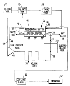
Figure 1 is a schematic flow diagram of a
pasteurization system incorporating electroheating
apparatus and methods in accordance with one embodiment
of the invention.
Figure 2 is a diagrammatic sectional view of
an electroheating unit utilized in the system of
Figure 1.
Figure 3 is a diagrammatic view depicting
portions of the apparatus shown in Fig. 2.
Figure 4 is a sectional view taken along line
4-4 in Fig. 2.
Figure 5 is a top plan view taken along line
5-5 in Fig. 4.
Figure 6 is a diagrammatic sectional view
depicting apparatus in accordance with a further
embodiment of the invention.
Figure 7 is a diagrammatic view similar to
Fig. 3 but depicting apparatus in accordance with a
further embodiment of the invention.
Figure 8 is a diagrammatic view similar to
Fig. 3 but depicting apparatus in accordance with yet
another embodiment of the invention.
Figure 9 is a diagrammatic sectional view
depicting apparatus in accordance with still another
embodiment of the invention.
Figure 10 is a further diagrammatic sectional
view depicting apparatus in accordance with another
embodiment of the invention.
Figure 11 is another diagrammatic section
view, similar to Fig. 10 but depicting apparatus in
accordance with yet another aspect of the invention.
- - ~~~~439
- 15 -
DETAILED DESCRIPTION OF THE PREFERRED EMBODIMENTS
General System Operation
A pasteurization system in accordance with
one embodiment of the present invention incorporates a
holding tank 10 for retaining an electrically
conductive fluid material to be processed. A balance
tank 12 is connected to the holding tank, and an outlet
from the balance tank is connected to the inlet of a
timing pump 14. The output of timing pump 14 in turn
is connected to a product side 18 of a plate-type heat
exchanger 20 referred to as the "regeneration section."
The outlet of product side 18 is connected the inlet of
a product side 26 of another plate-type heat
exchanger 28 referred to as the heating section. The
outlet of product side 26 in turn is connected to the
inlet 32 of an electroheating cell 34. The outlet 36
of the electroheating cell 34 in turn is connected to a
set of holding tubes 38, connected to in series with
one another. The last holding tube in the series is
connected to the inlet of a flow diversion valve 30.
The flow diversion valve is arranged to direct material
from the holding tubes through a first outlet 42 if the
temperature of the material is below a preselected
minimum and to direct the material through a second
outlet 44 if the temperature of the material is above
the preselected minimum. The first outlet 42 of flow
diversion valve 40 is connected to balance tank 12,
whereas the second outlet 44 is connected to the inlet
of a hot side 46 in regeneration section heat
exchanger 18. The outlet of hot side 48 in turn is
connected to an inlet of a refrigeration cooling
device 50. The outlet of hot second side 48 in turn is
connected to an inlet of a refrigeration cooling
device 50. Fluid material passing through the hot
side 46 of regeneration section heat exchanger 18 will
~I~~1~39
- 16 -
be in thermal exchange relationship with material on
the product side 18 of the regeneration section heat
exchanger, but will not be in contact therewith.
Stated another way, the regeneration section heat
exchanger permits exchange of heat between the material
on the hot side and the product side, but prevents
commingling of these materials. Heating section 28
also has a hot side 27 in thermal exchange relationship
with first side 26 but not in communication therewith.
An inlet of hot side 27 is connected to a source of hot
water (not shown) and an outlet of the hot side 27 is
connected to a water outlet, which in turn feeds back
into the hot water source for reheating.
Cooling device 50 is arranged to bring the
material passing through it to a temperature suitable
for packaging. The outlet of the cooling device is
connected to the product inlet of packaging
equipment 52. Cooling apparatus 50 may incorporate a
mixing device for mixing previously cooled material
with the material passing from the system. One such
mixing device is a so-called "y-shaped" mixer as
described, for example, in the United States
Patent 5,290,583. Such device has two inlet conduits
and an outlet conduit, the inlet conduits merging with
one another in a mixing chamber so that hot material
can be intimately admixed with cold, already
pasteurized material and chilled rapidly. Such mixing
devices can also be used immediately downstream from
the outlets 44 of the flow diversion valve so as to
cool the material almost instantaneously from above the
required minimum temperature as it exits from the
holding tubes 38.
Apart from electroheating cell 34, the
aforementioned elements of the apparatus may be of
generally conventional construction. Where the
21(1439
- 17 -
material to be processed is food product, a medical
product, body fluid or other product requiring sanitary
precautions, the elements of the apparatus discussed
above are constructed in accordance with conventional
sanitary engineering standards and practices.
In general, the pasteurization system
operates as follows: material to be pasteurized passes
from the holding tank 10 through the balance tank 12
and timing pump into the product side 18 of the
regeneration section, where it is initially preheated
by thermal exchange from outgoing material. The
incoming material from the product side of the
regeneration section is then further preheated by
thermal exchange from hot water in the heating
section 28, whereupon the material passes into the
electroheating cell 34. As further discussed below,
the material is rapidly heated in the electroheating
cell to above the desired minimum pasteurization
temperature. The heated material remains as close to
this peak temperature as it passes through insulated
holding tubes 38. The time for the material to pass
from the outlet 36 of the electroheating cell to flow
diversion valve 40 is fixed by the geometry of the
system and the flow rate established by timing pump 14.
This time is selected so that the time for the material
to pass from cell 36 to valve 40 is at least as long as
the required minimum pasteurization time. Thus, if the
material is at a temperature above the minimum
pasteurization temperature when it arrives at diversion
valve 40, it is known that the material has been held
at above the minimum pasteurization temperature for at
least the required pasteurization time. Provided that
the material is at the required temperature, it passes
through outlet 44 to the second side 46 of the
regeneration section heat exchanger, where it gives up
~1~~43~
- 18 -
some heat to incoming material and drops rapidly below
the minimum pasteurization temperature and then passes
to cooling section 50 where it is brought to the
desired temperature for packaging. However, if the
material reaching flow diversion valve 40 is not at the
required minimum temperature, it passes back through
outlet 42 to the balance tank 12 where it is passed
again through timing pump 14 and through the process
once again.
Electroheating Cell Construction
Electroheating cell 34 is shown in greater
detail in Figs. 2-4. The direction from the inlet 32 of
the cell to the outlet 36 is referred to herein as the
"downstream" direction of the cell, whereas the
opposite direction is referred to as the "upstream"
direction. The cell includes a dielectric structure
including a first elongated dielectric tube 60 defining
a first elongated cylindrical conduit 62. Conduit 62
has a central axis 64, an inlet end 66 and an outlet
end 68. Conduit 62 is circular in cross-section and
has a constant diameter D~ (Fig. 3). The length L~ of
tube 60 and conduit 62 is shortened in Fig. 2 for
illustrative purposes; in actual practice, the length
of the conduit may be many times its diameter. The
dielectric structure further includes a first or
upstream transition section 70 having a wall defining a
generally conical transition passageway 72 coaxial with
conduit 62 at the first end 66 of the conduit.
Transition passageway 72 has a progressively increasing
diameter in the upstream direction, away from inlet
end 66 and tapers inwardly in the downstream direction
to a diameter D~, equal to the diameter of conduit 62
immediately adjacent the inlet end of the conduit.
Transition section 70 has a flat contact face 74 at its
- - '1~Q439
- 19 -
end remote from conduit 62, face 74 being substantially
perpendicular to the axis 64 of the conduit and
transition passageway. The conical transition
passageway 72 forms a circular opening of diameter D2 at
face 74.
The dielectric structure further includes a
second or downstream transition section 76 associated
with the outlet end 68 of conduit 62, the second
transition section defining a generally conical second
l0 transition passageway 78 merging with the outlet end 68
of the conduit and having progressively increasing
cross-sectional area in the downstream direction away
from the outlet end 68. Second transition
passageway 78 terminates in a circular opening at a
flat face 80 on the end of transition section 76 remote
from the conduit. The configuration of the second
transition section and second transition passageway are
essentially identical to that of the first transition
section and transition passageway discussed above.
The dielectric structure further includes a
second elongated dielectric tube 82 defining a second
conduit 84 having an inlet end 86 and an outlet end 88;
a third transition section 90 defining a generally
conical transition passageway 92 at the inlet end 86 of
the second ccnduit 84 and a fourth transition
section 94 defining a conical transition passageway 96,
at the outlet end 88 of second conduit 84. Second
tube 82, third transition section 90 and fourth
transition section 94 are substantially identical to
the first tube 60, first transition section 70 and
second transition section 76 discussed above, except
that the length LZ of the second conduit is slightly
greater than the length L~, of first conduit 62, for
reasons further discussed below.
~15~439
- 20 -
The components of the dielectric structure
can be fabricated from essentially any dielectric
material which has adequate physical and dielectric
strength and which is suitable for contact with the
material to be treated. In the case of foods,
beverages and pharmaceuticals, the materials normally
must meet applicable governmental regulations. For
typical foods and pharmaceuticals, materials such as
acetal polymers such as those sold under the registered
l0 trademark DELRIN by the DuPont Company an3 those sold
under the registered trademark CELCON by the Celenese
Corporation can be used, as well as glass, certain hard
rubber compositions and thermosetting polymers such as
phenolics. Polyetherimide resins of the type sold
under the trademark ULTEM by the General Electric Co.
of Schnectady, New York are especially preferred.
The electroheating unit further includes a
first electrode body 98 defining a first electrode
surface 100. Surface 100 is a portion of a spherical
surface having its center 102 on axis 64, substantially
at the apex of the conical transition passageway 72.
Stated another way, the generator of the conical
surface of the transition passageway passes 72 through
or adjacent the center 102 of spherical electrode
surface 100. First electrode body 98 has a flat
surface mating with the flat surface 74 of the first
transition section 70. Spherical surface 100
intersects the flat surface of the electrode body along
a circular boundary having a diameter, measured about
the central axis 64 substantially equal to the
diameter Dz of the open end of the transition passageway
or just slightly less than D2. Thus, the wall of the
transition section 70 merges with the electrode body
around the periphery of spherical electrode surface
~35 100.
~1~4439
- 21 -
First electrode body 98 has an input
surface 102 substantially perpendicular to central
axis 64 and facing upstream in the opposite direction
from spherical first electrode surface 100. A conical
flow spreader 104 projects from surface 102 on the
central axis 64. First electrode body 98 has four
ports 106 extending through it, from surface 102 to
surface 100. Each port 106 has an input axis 108 lying
in a plane remote from the central axis 64 of the
spherical surface 100. Thus, axis 108a of port 106
disposed at the top of the drawing in Fig. 4 lies in a
generally horizontal plane above central axis 64,
whereas axis 108b of port 106b disposed at the right-
hand side of the drawing in Fig. 4 lies in a vertical
plane to the right of axis 64 and so on. Each port
axis 108 is disposed at an oblique angle 110 to the
projection of central axis 64 into the plane of the
port axis 108. Stated another way, the axes 108 of all
of the ports 106 slope in the same direction with
respect to central axis 64 so that the ports are
disposed in a generally helical pattern. A particle
moving through any port 106 in the direction from input
surface 102 to electrode surface 100 will be moving
counter-clockwise to axis 64, as seen from a point on
axis 64 downstream of the electrode surface.
The apparatus further includes a central
electrode body 110 defining a spherical second
electrode surface 112 and spherical third electrode
surface 114 arranged back to back. Second electrode
surface 112 faces upstream towards the second
transition passageway 78 whereas the third electrode
surface 114 faces downstream towards third transition
passageway 92. Each of these spherical surface 112
and 114 is centered on central axis 64. Each such
spherical surface has essentially the same
~1~0~~~
- 22 -
configuration and relationship with the associated
transition passageway as discussed above with reference
to the first electrode surface 100. Thus, in the same
manner as discussed above, the wall of second
transition section 76 joins the central electrode
body 110 around the periphery of second electrode
surface 112, whereas the wall of third transition
section 90 joins the central electrode body 110 around
the periphery of third electrode surface 114. The
central electrode body 110 has four ports 116 of which
only some are visible in Fig..2. Each such port
extends through the electrode body from second
electrode surface 112 to third electrode surface 114.
Ports 116 are disposed in a generally helical
arrangement similar to the ports 106 of the first of
upstream electrode body 98. That is, the axis of each
port 116 is sloped so that a particle moving along the
axis of each port 106, from surface 112 to surface 114
will move counter-clockwise around central axis 64 as
seen from a point on the central axis downstream from
the central electrode body.
The apparatus further includes a third or
downstream end electrode body 118 defining a fourth
electrode surface 120. Body 118, electrode surface 120
and their relationship with the associated fourth
transition section 94 are identical to the
corresponding features of the upstream, first electrode
body 98 and the associated first transition section 70.
However, the fourth electrode surface 120 faces
upstream whereas the spreader 124 of the downstream
electrode body faces downstream.
The apparatus further includes an inlet
cover 126 attached to the upstream or inlet face 102 of
the first, upstream electrode body 98, the inlet
cover 126 defining a conical inlet passage extending to
~1~0439
- 23 -
the openings of the ports 166 in body 98. An inlet
pipe 128 is connected to inlet cover 126. The inlet
pipe has a conventional fitting 130 at its end remote
from the inlet guide for connection to the remainder of
the system. An outlet cover 132, outlet pipe 134 and
outlet pipe connection 136, substantially identical to
the corresponding inlet features are connected at the
downstream end of the downstream electrode body 118.
Each of electrode bodies 98, 110 and 118 can
be formed from substantially any electrically
conductive material which is acceptable for contact
with the material to be processed and which resists
corrosion and electrolytic effects. Materials such as
stainless steel, titanium, nickel and other metals and
alloys can be employed. However, carbonaceous
materials, i.e., materials consisting essentially of
carbon, are particularly preferred. Such materials
include graphite, pitch, diamond and diamond-like forms
of carbon. Graphite is particularly preferred. One
form of graphite which can be used is sintered graphite
such as that sold under the designation XT graphite and
XT-CF graphite by Poco Graphite Incorporated of
Decatur, Texas. The XT-CF graphite is pretreated by an
alcohol impregnation process so as to minimize water
absorption during use, and is preferred. Another
preferred material includes graphite with a surface
layer of pyrolytic carbon to reduce porosity. One such
material is sold under the designation "PYE COATED"
carbon by Poco Graphite Incorporated. The entire
electrode can be formed from sintered graphite.
Alternatively, a carbonaceous material can be applied
over a metallic body, so that the surface in contact
with the product being treated is formed from the
carbonaceous material. The carbonaceous materials, and
particularly graphite, resist electrolysis and
- ~1~043~
- 24 -
corrosion in service. Moreover, graphite, as well as
other carbonaceous materials, tends to minimize
electrolysis of the product being treated and,
particularly, tends to suppress gas formation. The
advantageous properties of the carbonaceous electrodes
can be applied in electroheating apparatus of any
configuration. Each electrode body is provided with a
band 140 of a highly conductive material such as copper
and encircling the exterior surface of the electrode
body, remote from the material to be processed. Each
band is connected to a tap 142 for connection of the
electrode to an external potential.
The electrode bodies are secured to the
adjacent components by bolts 138 passing through the
electrodes outside the periphery of the electrode
surfaces. The central electrode body 110 and the
associated bolts are covered by a protective shroud 146
formed from a dielectric material. O-rings or similar
seals may be provided between the surfaces of the
electrodes and the mating surfaces of the other
components. The tubes 60 and 82 defining the first and
second conduits may be secured to the transition
sections by threaded fastening, slip fit fastening or
other conventional fastening arrangements. Of course,
where used in contact with food, pharmaceuticals or
other materials requiring sanitary precautions, the
various components should be designed in accordance
with known principles of food equipment engineering,
and in accordance with applicable codes and standards,
so as to facilitate cleaning and prevent build-up of
contaminated material within the apparatus.
The upstream or inlet end electrode body 98
and the downstream or outlet end electrode body 118 are
both connected to ground potential, whereas the central
electrode body 110 is connected to a mains frequency
~1~~~39
- 25 -
alternating potential source 148, arranged to apply a
potential with respect to ground alternating at a
preselected frequency, desirably less than about 100 Hz
and more desirably about 50-60 Hz. Source 148 may
include a direct connection between the electrode
body 110 and the utility line or else may include a
transformer (not shown) interposed between the
electrode 110 and the utility power line.
Electroheater Operation
to In operation, material to be treated,
preheated in the regeneration section 20 and heating
section 28 of the heat exchange (Fig. 1) passes into
the inlet 32 of the electroheating cell, and thus
passes through the inlet pipe 128 and inlet cover 126.
The flowing material diverges outwardly around the
spreader 104 of upstream electrode body 98 and passes
through the ports 106 in the electrode body. As the
material passes through the port, it enters the first
transition passageway 72 with a swirling motion, in the
counterclockwise direction around the central axis 64,
and passes through the first conduit 62 and through the
second, conical transition passageway 78 to central
electrode body 110. The material passes through the
ports 116 in the central electrode body, and again is
guided into a swirling motion about the central
axis 64. It passes downstream through the third
transition section and the second conduit 84 to the
fourth transition passageway 96 and then flows through
the ports of the downstream electrode body 118 and out
through the outlet cover 132 and outlet pipe 134 to the
outlet 36 of the electrode heating unit. The swirling
motion of the material passing through the unit helps
to assure that the material does not stagnate at any
point within the unit.
~1~~1~~9
- 26 -
As the electrically conductive, flowing
material passes through the unit, it contacts the
electrode surfaces. Thus, the material momentarily
positioned between the upstream electrode body 98 and
the central electrode body 110 is in electrical contact
with the first electrode surface 100 and the second
electrode surface 112. Source 148 imposes a potential
difference between these two electrode surfaces,
causing current to flow through the material and heat
the material. This current is substantially uniformly
distributed over electrode surfaces 100 and 112. As
best illustrated in Fig. 3, each electrode surface lies
at a substantially uniform distance from the associated
opening of conduit 62. Thus, any point on first
electrode surface 100 lies at a distance approximately
equal to the radius R~ of surface 100 from the first or
upstream end of conduit 66 whereas any point on second
electrode surface 112 lie at substantially the same
distance from the end or downstream end 68 of
conduit 62.
As the openings of the conduit are circles of
finite diameter D~, the distance from a given point on
an electrode surface to one point within the opening
may differ slightly from the distance from the same
point on the electrode surface to another point in the
same opening. However, the diameter D~, of the openings
is substantially smaller than the radius R1, of each
electrode surface. Typically, the ratio to electrode
surface radius R~ is at least about 2Z:1, and most
preferably more than about 6:1. With this electrode
surface configuration, the shortest path from any point
on electrode 100 to another point on second electrode
surface 112 is substantially the same f or any pair of
points on the two surfaces. That is, the shortest path
from point P, through conduit 62 to point P~ on second
~1~~439
- 27 -
electrode surface 112 would be substantially the same
as the length of the shortest path from point Pb on the
first electrode surface to point P~,, and these lengths
in turn would be the same as the shortest path length
from point P, or point Pb on first surface 100 to point
Pd on second surface 112. Preferably, the shortest path
lengths for any points on the surfaces differ by less
than about 5 percent.
Because the path length from any point on the
first electrode surface to any point on the second
electrode surface is substantially the same, the
electrical resistance from any point on the first
electrode surface 100 to any point on the second
electrode surface 112 is substantially the same as the
electrical resistance for any other points on the two
surfaces. Therefore, electrical current passing
between first electrode surface 100 and second
electrode surface 112 is substantially uniformly
distributed over both of these electrode surfaces. The
maximum current density at any point on the electrode
surface desirably is no more than about 105% of the
average current density for the entire electrode
surface. Thus, the maximum and average current density
at the electrode surface is substantially equal to the
total current divided by the area of each electrode
surface. ° -
Because the cross-sectional area of
conduit 62 is substantially smaller than the cross-
sectional area of the electrode surfaces, the current
density and the electrical resistance per unit length
along axis 64 are substantially higher in the conduit
than in the transition passageways adjacent the
electrode surfaces. Preferably, the ratio between the
area of each electrode surface and the mean cross-
sectional area of conduit 62 is at least about 5:1,
~1a4439
- 28 -
preferably at least about 10:1 and most preferably at
least about 35:1 or more. The ratio of the maximum
current density in the conduit to the current density
at the electrode surface will have similar values, as
will the resistance per unit length along the upstream-
to-downstream axis 64. At any point along the
upstream-to-downstream axis, the rate of power
dissipation and the rate of heat evolution is IZR, where
I is the current and R is the resistance at such point.
I is the same at all points, whereas R is very low
adjacent the electrodes and very high within conduit
62. Thus, essentially all of the electrical energy
dissipated between the first electrode surface and the
second electrode surface is dissipated in conduit 62.
The flowable material passing through the system is
substantially heated by internal resistance heating
while passing through the conduit, but is not
substantially heated in the vicinity of the electrode
surfaces.
Exactly the same relationships apply with
respect to the material momentarily disposed between
third electrode surface 114 and fourth electrode
surface 120. Once again, essentially all of the
heating will occur inside conduit 84, and little or no
heating will occur within the transition passageways 92
and 96.
Because the upstream or inlet end electrode
body 98 and downstream or outlet electrode body 118 are
both maintained at ground potential, there is
essentially no leakage of electrical current from the
electroheating unit to the other portions of the
system.
Process Parameters
- - z~~o~30
- 29 -
Essentially any amount of heat can be
provided to the material passing through the
electroheating cell. One method of selecting process
parameters starts with the amount of heat to be applied
in the electroheater. That amount in turn is
determined by the desired temperature entering the
preheater 32, the temperature desired at the
electroheater output 36, the mass flow rate of material
per unit time and the specific heat of the material.
The product of the difference between inlet and outlet
temperatures, the flow rate and the specific heat gives
the needed energy input per unit time in the entire
electroheater. For a system with two separate heating
regions and four electrode surfaces, the total energy
input is divided as desired to give the desired energy
input per unit time per region. The energy input per
unit time of course converts directly to power.
Typically, the energy input is calculated in
kilocalories/Hr and this number divided by 860 yields
the electrical power in kilowatts required.
Essentially any voltage may be used.
Voltages of about 100 volts to about 15 Kv are readily
available in industrial power systems. Voltages above
about 220 volts, are preferred. The applied voltage
may have any frequency from 0 Hz (DC) to radio
frequencies, ypically up to about 500 KHz. Line
frequency below 100 Hz is preferred and about 50-60 Hz
is especially preferred. Assuming that the available
voltage from source 148 is fixed, division of the
calculated power by the voltage yields the required
current flow for each pair of electrodes. The required
resistance between electrodes is calculated by dividing
the assumed voltage by the calculated current flow.
Once the calculated resistance has been found, the
dimensions of the cell are effectively fixed. Using
2150439
- 30 -
the assumption that substantially all of the electrical
resistance between the electrodes is in the conduit,
the resistance is substantially equal to
R
ABC
where R is the electrical resistance in ohms;
L~ is the length of the conduit;
A~ is the cross sectional area of the conduit; and
C is the specific electrical conductivity of the
material being heated, expressed as I~iO/cm/cmz.
The cross-sectional area typically is
selected to accommodate the flow of the fluid with a
reasonable pressure drop. For a given material and for
a given conduit cross-sectional area, L~ is directly
derivable from the desired resistance value R:
L~ = RA~C .
The value of conductivity C will vary with
the material and will also vary with the temperature of
the material itself. Thus, as the material is heated
the value of C typically increases. In typical
processes, a reasonably accurate estimate of C for each
section can be obtained by taking the arithmetic mean
between the value of C at the inlet to the section and
the value of C at the outlet. Where the material is
heated through a very large temperature range, or where
the variation of C with temperature for the material is
particularly large, a more accurate value of C can be
obtained by plotting the logarithm of C against
temperature and determining the value for the logarithm
of C at a mean between the inlet temperature to be
sectioned and the outlet temperature from the section.
In a four-surface, two-section unit as illustrated in
Fig. 2, the material passing through the second section
will have a substantially higher mean temperature than
the material in the first section and thus a higher
~1~0~39
- 31 -
value of C. To provide equal currents and equal power
division between the two sections, the value of I~ for
the second or downstream section will be greater than
the value of I~ for the first or upstream section; the
second conduit 84 will be longer than the first
conduit 62. Alternatively, the second conduit can be
formed with a somewhat smaller cross-sectional area A~.
However, equal power division between the two sections
is not essential. In many cases, the downstream
section has equal or smaller conduit length than the
upstream section, so that the downstream section
carries more power and provides a higher heating rate
than the upstream section.
For many materials there is a critical,
maximum current density which can be tolerated at the
electrode surface. This critical current density can
be determined by testing the material at progressively
increasing current densities until arcing occurs at the
electrode surface. For liquid egg, as defined
hereinbelow, the critical current density is
approximately 0.25 amps/cm2. For whole milk, the
critical current density is about 0.40 amps/cm2 and
for 0.5 percent saline solution, the critical current
density is about 1.0 amps/cm2. Thus, the required
current is~divided by the area of the electrode
surfaces. If the result is below the critical current,
density for the material, the result is satisfactory.
If not, the current must be reduced either by
increasing the number of regions, and hence the number
of electrodes, by raising the resistance of each stage
or by increasing the surface area of the electrodes.
The heating time in the electroheater is
directly related to the volume of the electroheater
(principally the volume of the conduits 62 and 84) and
inversely related to the flow rate of the material.
21~~439
- 32 -
The internal volume of the heater can be controlled by
controlling the diameter of the conduits 62 and 84. As
the diameter and hence the cross-sectional area of the
conduits are reduced, the conduit length can remain the
same if the voltage is increased, or else can be
reduced to maintain a constant resistance. Either
approach leads to a shorter residence time. The lower
limit on the conduit internal diameter is set by
considerations of increasing flow resistance at smaller
diameters, which lead to extremely high pressures
within the system and high pumping loads and by
considerations of mechanical shear damage to the
product. However, in practical systems, the residence
time of the material within the electroheater may be
only a small fraction of a second, and the heating rate
may be hundreds or even thousands of degrees per
second.
Numerous variations and combinations of the
features discussed above can be utilized without
departing from the present invention.
Additional Structures
As illustrated in Fig. 6, one such variant
includes a first or upstream body 298 defining a first
electrode surface 200; a central electrode body 210
defining a second electrode surface 212 and third
electrode surface 214 and a downstream or outlet
electrode body 218 defining a fourth electrode
surface 220. The electrode bodies are substantially
similar to the electrodes discussed above with
reference to Figs. 2-5. Also, the apparatus of Fig. 6
includes a dielectric structure having a first, rigid
tube 260 defining a first conduit 262 and also having
transition sections 259 and 261 connecting the ends of
the conduit 262 with a first and second electrode
~1~0~~9
- 33 -
surface 212. These elements are also similar to the
first tube and transition sections discussed above.
The dielectric structure in Fig 6. however includes a
flexible, elastomeric tube 282 defining the second
conduit 284, disposed between the third electrode
surface 214 and the fourth electrode surface 220.
Conduit 284 is connected by rigid transition
sections 290 and 294 to the electrode bodies 210
and 218, the transition sections being similar to those
discussed above. A hollow dielectric shell 285
surrounds the exterior of tube 282 and defines a sealed
space 283 between the exterior of the tube and the
interior of the shell.
Space 283 is connected to a gas source 285
and vent 287 by an electropneumatic control system 289.
A current sensor 271 is connected between the
downstream or outlet end electrode body 218 and ground,
whereas a similar sensor 273 is connected between the
inlet, upstream end electrode body 298 and ground. As
in the embodiment discussed above, the central
electrode body 210 is connected to an alternating
current potential source. Sensors 271 and 273 are
connected to the control system 289. In operation,
control system 289 compares the readings from the two
sensors. The reading of sensor 273 gives the current
flowing in the first heating region, through
conduit 262 from the center electrode body to the
upstream electrode body 298. Sensor 271 reads the
current flowing in the second or downstream heating
region, within conduit 284. If the current in the
second region, detected by sensor 271, exceeds the .
current in the first region, the control means admits
gas 285 into space 283 so as to raise the pressure
therein and deform tube 282 inwardly, thus bringing the
tube to the position illustrated in broken lines in
~1.~0~39
- 34 -
Figs 6-7. This reduces the cross-sectional area of
conduit 284, thereby increasing the electrical
resistance in the second or downstream section and
reducing the current. If the current in the second
section falls below that in the first section, the
control system 289 actuates vent 287 to release some of
the gas from space 283, thereby reducing the pressure,
allowing the wall of tube 282 to bulge outwardly back
towards the position illustrated in solid lines or even
further outwardly, thereby increasing the mean cross-
sectional area of the conduit 284, decreasing the
resistance and increasing the current in the second
section. In this manner, the system provides control
of the resistance, and provides control of the
resistance in the second section without disassembly of
the apparatus and without interruption of product flow.
In a variant of this approach, the variable
diameter conduit could be provided in both sections,
and the control means could be arranged to adjust the
diameters of both conduits 262 and 282. In such an
arrangement, the variable diameter conduits can be
employed to adjust the resistance of both sections as
required to compensate for changes in the resistivity
of the product caused by changes in composition and
temperature of the incoming product; to compensate for
changes in the amount of heating required, and to
compensate for changes in the applied voltage, as well
as to balance the current flows between the two
sections. All of these changes can be accomplished
without interrupting the productivity of the system.
In the arrangement of Fig. 6, the cross-
sectional area of the conduit is varied by applying
fluid to the exterior of a flexible tube. However, the
cross-sectional area can be varied by mechanically
pinching a flexible tube between a pair of opposed
~~.~9~39
- 35 -
members. It can also be varied by mechanically pulling
the ends of a flexible tube defining the conduit away
from one another so as to elongate the tube. This
causes the tube to stretch and narrow, thereby reducing
the cross-sectional area of the conduit and also causes
the length of the conduit to increase, thus
additionally raising the resistance. The tube defining
conduit may be deformable only in the lengthwise
direction, as where the tube is formed from several
sections telescopically received in one another.
Therefore, the length of the conduit may be increased
or decreased without appreciably altering the diameter,
and without disassembly. This effect provides similar
control of capabilities to those discussed above. In
yet another variable geometry arrangement, one or more
dielectric elements may be mounted within the conduit
so as to occlude a portion of the conduit. These
elements may be mounted for movement relative to the
conduit or relative to one another so as to vary the
degree of such occlusion and thereby vary the mean,
cross-sectional area of the conduit. For example, the
tube may be provided with a conical valve element
movable along the axis of the conduit and a conical
valve seat fixed in the conduit so that the valve
element can be moved towards an3 away from the seat.
In the arrangements discussed above, the
conduits are straight circular cylinders of uniform
diameter and coaxial with one another. The electrode
surfaces are spherical regions concentric with the
single axis of the cylinders. However, other
arrangements may be employed. As illustrated in
Fig. 7, the conduit 362 defined by the dielectric
structure 360 may be a passageway of generally circular
cross-section but of arbitrary configuration such that
the central axis of the conduit turns in varying
~1~~J439
- 36 -
directions along the length of the conduit. In this
case, the conduit nonetheless defines a central
axis 364 at its inlet end and another, different
central axis 365 at its outlet end. A first electrode
surface 300 in the form of a surface of revolution may
be concentric with the axis 364 at the inlet end of the
conduit whereas a second electrode surface 312 may be
concentric with the axis 365 of the conduit at the
outlet end. The conduit may have other shapes such as
a U-shape or helical shape to provide a compact
assembly.
It is not essential that the conduit have a
circular cross-section. As illustrated in Fig. 8, the
conduit 462 defined by the dielectric structure 460 may
have a generally rectangular cross-section. Thus, one
cross-sectional plane of the conduit is shown in broken
lines after 463 in Fig. 8. The conduit has an inlet
end 466 and an outlet end 468. The opening at inlet
end 466 has a long axis A~~ and a short axis ASS,
perpendicular thereto. The first electrode surface 400
adjacent the inlet end of the conduit is substantially
in the form of a cylinder having its axis coincident
with the long axis A~~ of the adjacent conduit opening.,
Likewise, the opening of the conduit at the outlet
end 468 is generally in the form of a highly elongated,
narrow rectangle having a short axis ASZ and a long axis
A~2. The second electrode surface 420 is substantially
in the form of a portion of a circular cylindrical
surface having an axis coincident with the long axis A~2
at the opening 468. Each of the transition passageways
is generally in the form of a V-shaped channel with the
narrow end of the V at the end of the conduit and with
the wide end of the V intersecting the electrode
surface.
~1~t~439
- 37 -
Here again, the cross-sectional area of the
conduit, taken in a plane such as plane 463
perpendicular to the length of the conduit is
substantially less than the area of each electrode
surface 400 and 420. In use, an electrically
conductive material may be passed through the conduit
lengthwise, in the flow direction denoted by arrows F~.
An electrical potential may be applied between the
electrodes 400 and 420, and will provide a current
1o density within the conduit substantially higher than
the current density at the electrodes. Here again, the
shortest path between any point on electrode 400 and
any point on electrode surface 420 via the course or
conduit 462 will have substantially the same length as
the shortest path between any point on electrode
surface 400 and any other point on electrode
surface 420. That is, the shortest path distance
between any two points on the electrode surfaces is
substantially the same regardless of the particular
points selected. Accordingly, the current will be
substantially uniformly distributed over the electrode
surfaces. The ends of the transition passageways and
the edge of the conduit visible at the front of the
drawing in Fig. 8 are blocked by further dielectric
walls (not shown) and the electrodes are provided with
appropriate ports (not shown).
In a system according to yet another
embodiment, the electroheater includes a first,
generally plate-like conductive electrode 500 and a
second plate-like conductive electrode 520. The
dielectric structure includes a dielectric tube 560
extending between the electrodes and a dielectric
packing including a large number of small spheres,
chips, rings or other pieces of dielectric material
disposed within the dielectric tube intermediate
~1a~~3~
- 38 -
between the electrodes. The tube and packing
cooperatively define a large number of parallel
continuous paths 510 extending between electrode 500
and electrode 520. These paths extend through
interstices between the particles of the packing and
join with one another at various points within the
packing. However, the various paths can be said to
cooperatively define a unified continuous course
extending between the electrodes. The continuous
course has a cross-sectional area, taken in any
arbitrary cutting plane 563 perpendicular to the length
of the course (perpendicular to the electrode to
electrode direction) equal to the aggregate cross-
sectional area of the individual continuous paths.
Within the packing this aggregate cross-sectional area
is substantially less than cross-sectional area of
tube 560 and substantially less than the surface area
of the electrode surfaces defined by electrodes 500
and 520.
Apparatus according to this embodiment can be
used in substantially the same manner as that described
above. Here again, because the cross-sectional area of
the course remote from the electrodes is substantially
smaller than the surface area of the electrodes
themselves, the current density within the course (in
the interstices between the packing particles) will be
substantially greater than the current density at the
electrodes. The size of the packing particles is
exaggerated in Fig. 9 for clarity of illustration. In
actual practice, the packing particles may be very
small by comparison to the size of the electrodes and
in comparison to the diameter of tube 562.
Accordingly, the openings of the various continuous
paths at the surfaces of the packing can be
substantially uniformly distributed over the ends of
~15~439
- 39 -
the packing, so as to provide substantially uniform
path lengths between any points on the surfaces of the
electrodes.
The methods and apparatus according to the
present invention can also be used to heat slurries and
particulates. The term "slurry" as used herein refers
to any mixture of solid particles in a liquid phase.
Thus, many common industrial and food products are
slurries, such as stews, soups and the like. Food
l0 products containing plant or animal tissues desirably
are maintained under pressure while passing through the
electroheating apparatus. The pressure minimizes
tissue damage and consequent loss of texture during the
heating operation. Also, where a particulate solid
must be heated, the particles can be mixed with a
carrier liquid to form a temporary slurry for
electroheating. The liquid phase should have at least
some electrical conductivity so that current can be
transferred from the electrodes, through the liquid
phase to the particles as the slurry passes through the
electroheater. However, it is desirable to concentrate
the flow of current through the particles, rather than
through the liquid phase. The ratio of particle volume
to fluid volume should be as high as possible
consistent with the ability to pump the slurry. With
large, noncompressible particles, a typical slurry may
contain about 70 percent particles by volume.
Desirably, the liquid phase has a lower
conductivity than the particles. This can be achieved
through control of the fluid composition itself as, for
example, by using wholly or partially deionized or
distilled water in the liquid phase. Alternatively,
the relative conductivities of the particles and fluid
can be controlled by controlling the temperature of the
two phases as they enter the electroheater. Where
~1~fl43fl
- 40 -
conductivity of the particles increases with increasing
temperature, the particles can be preheated either by a
preliminary electroheating operation or by
conventional, conductive, microwave or other heating.
If only the outer layers of a particle are preheated,
the current will concentrate in the outer layers, and
may leave the center of each particle inadequately
heated. Therefore, the particle preheating may be
conducted by first applying heat to the particles and
then allowing the particles to dwell and come to
thermal equilibrium before electroheating. Desirably,
the preheating operation and dwell operations are
conducted so that the preheated particles, after the
dwell time, have center temperatures slightly higher
than the exterior temperatures of the particle, thereby
assuring that the current will pass through the center
of the particle.
Alternatively or additionally, the liquid
phase can be cooled prior to formation of the slurry.
The residence time of the particles and the liquid in
the electroheater can be very short, on the order of a
second or even less. In this time, there will not be
appreciable heat transfer between the liquid and the
solid particles. By cooling the liquid, its specific
conductivity will be reduced, thus tending to
concentrate more of the current in the electroheater
within the particles.
The nature of the electroheating process
reinforces the effects of any attempts to concentrate
the current within the particles. That is, if the
particles and liquid are introduced into the
electroheater under conditions which tend to promote
current flow through the particles rather than through
the liquid, the particles will be heated more than the
liquid, reducing the resistance of the particles more
z~~o~~~
- 41 -
than the liquid and concentrating the current flow to
an even greater degree in the particles.
Apparatus according to yet another embodiment
of the present invention is illustrated schematically
in Figure 10. The apparatus of Figure 10 includes a
first electrode 600, a second electrode 612 and a
dielectric structure 660 defining a course between
these electrodes. Here again, the course includes a
first, tapered transition passageway 672 adjacent the
first electrode, a second tapered transition
passageway 678 adjacent the second electrode and a
relatively narrow conduit 662 between these transition
passageways. The course is subdivided by an upstream
porous barrier 601 between the first transition
passageway 672 and conduit 662 and by a downstream
porous barrier 603 between the conduit and the second
transition passageway 678, so that the porous barriers
effectively subdivide the course into three zones: a
first zone consisting of transition passageway 672
disposed adjacent first electrode 600; a second zone
consisting of the conduit 662 and a third zone
consisting of transition passageway 678 adjacent the
second electrode. The dielectric structure has a fluid
inlet 605 communicating with central zone or
conduit 662 adjacent upstream barrier 601 and
outlet 607 communicating with the central zone adjacent
the opposite, downstream barrier 603. First zone 672
also has an inlet 673 and an outlet 675, whereas the
second zone 678 has an inlet 679 and an outlet 681.
The inlet and outlet of zone 672 are connected to an
electrolyte supply apparatus 683 whereas the inlet and
outlet of zone 678 are connected to a separate
electrolyte supply apparatus 685.
As in the embodiments discussed above, first
electrode 600 and second electrode 612 are connected to
~1~fl439
- 42 -
a source of electrical power (not shown). Each
electrolyte supply apparatus is arranged to circulate
an electrolyte as further discussed below through the
associated zone of the apparatus and to maintain the
electrolyte in such zone under a preselected pressure.
In operation, the central zone inlet 605 is
connected to a source of product to be treated whereas
the central zone outlet 607 is connected to a product
receiving device as, for example, the heat exchangers
and cooling devices discussed above. The product to be
treated is passed through the central zone, but does
not pass through the first zone 672 or third zone 678
of the path. The electrolytes within these zones
conduct the current from the electrodes to the porous
barriers 601 and 603. The porous barriers also contain
some of the electrolyte and hence the electrolytes in
the porous barriers conduct the current through the
barriers to the material being treated in the central
zone.
The use of electrolytes and porous barriers
between the electrodes of an electroheating system and
the product being treated is disclosed in my previous,
commonly-owned copending United States Patent
Application No. 08/125,933, the disclosure of which is
hereby incorporated by reference herein. As set forth
in greater detail in said '933 application, porous
barriers 601 and 603 may be formed from ceramic
materials such as those sold by the Coors Ceramic
Company, having a porosity (for water) of at least
about 5.0 x 10'Z cc/cm2-Hr-PSI, wherein PSI refers to
pounds per square inch. The maximum porosity should be
about 5.0 and the preferred porosity is about 0.3, all
in the same units of porosity. The porous barriers may
be about 3mm thick and desirably less than about l.5mm
thick. The barriers may be structurally reinforced.
.. - ~1~~43~
- 43 -
Preferably, the electrolyte in each of
zones 672 and 678 is under a pressure slightly higher
than the pressure of the product being treated, so that
the product does not penetrate into the pores of the
barriers. The electrolyte should be compatible with
the product being treated, so that incorporation of
minor amounts of the electrolyte into the product due
to seepage through the electrodes will not impair the
product quality. Normally, the rate of seepage of the
electrolyte through the porous barrier is many orders
of magnitude smaller than the rate of product flow
through the central zone or conduit 662, so that the
electrolyte is added to the product in amounts
corresponding to parts per million or less. For food
products, aqueous solutions containing salts selected
from the group consisting of potassium chloride, sodium
chloride, calcium chloride, potassium sulfate and
sodium sulfates are preferred, and potassium chloride
solutions are especially preferred. Desirably, the
electrolyte contains the salt in a concentration such
as to impart maximum conductivity to the electrolyte.
Potassium chloride electrolytes desirably contain
about 30 percent by weight of potassium chloride. To
even further reduce the seepage rate,, the electrolyte
may contain a food-compatible gelling agent as, for
example, about 0.1% to about 0.5% by weight of an
alginate.
Apparatus according to yet another embodiment
of the invention is illustrated in Fig. 11. This
apparatus again includes a dielectric structure 760
defining a course including a first tapered transition
passageway 772 at one end of a relatively narrow
conduit 762 and a further tapering transition
passageway 778 at the opposite end of the conduit. A
fluid inlet 705 at the upstream end of the structure
~1~Q439
- 44 -
and a fluid outlet 707 at the downstream end allow for
passage of the electrically conductive fluid to be
heated in the upstream to downstream direction, through
the transition passageways and conduits.
A first composite electrode structure 700 is
defined by a plurality of subelectrodes 701. Each
subelectrode in turn includes a porous housing 702 and
an interior conductive element 703 disposed within the
housing. A conductive electrolyte is maintained within
each housing 702 so as to conduct current from the
interior conductive element 703 to the conductive fluid
passing through the structure. Each of these
subelectrodes 701 may include a generally rod-like
structure with arrangement for internal circulation of
electrolyte from an external source as disclosed in
certain preferred embodiments of the aforementioned
United States Patent Application 08/125,933. The
electrolytes, ceramics and electrolyte conditions may
be as discussed above and as described in said '933
application. The subelectrodes 701 and particularly
the external, porous ceramic shells 702 of the
subelectrodes, are disposed in a curved array so that
each subelectrode is at substantially the same distance
from the adjacent opening of conduit 762 as the other
subelectrodes in electrode 700. Thus, the
subelectrodes cooperatively constitute an electrode
disposed at a substantially uniform distance from the
conduit opening. Similarly, a second electrode 712 is
defined by additional subelectrodes 713, each having
the same construction as the subelectrode 701 discussed
above. Here again, all of subelectrodes 713 are
disposed at a substantially uniform distance from the
adjacent opening of conduit 762 so as to cooperatively
define an electrode surface disposed at a substantially
uniform distance from the conduit opening.
~1~~4~9
- 45 -
In operation, a power supply or potential
source 748 applies a potential, such as an alternating
potential as discussed above, across electrodes 700
and 712. All of the subelectrodes 701 constituting
electrode 700 are connected in parallel to the same
pole of potential source 748, so that all of the
subelectrodes 701 are at the same potential. Likewise,
all of the subelectrodes 713.constituting electrode 712
are connected to another pole of potential source 748,
so that all of subelectrode 713 constituting
electrode 712 are at the same potential. Thus, current
flows from the subelectrodes constituting electrode 700
to the subelectrodes constituting electrode 712, but
there is no current flow between the subelectrodes of
each individual electrode.
The principles of the invention are further
illustrated by the following illustrative, non-
limiting examples:
EXAMPLE 1
Using apparatus substantially as illustrated
in Figs. 1-5, liquid whole egg is pasteurized. The egg
passes from the outlet of the heat exchanger heating
section 27 to the inlet 32 of the electroheating cell
at a preheat temperature of about 55°C and at a flow
rate of about 3 Kg/sec. All of the electrodes have
peripheral diameter DZ (Fig. 3) of about 9.1 cm. Both
conduits are substantially rigid, have internal
diameter D~ of about 1.9 cm. The lengths L~ and L2 of
the first and second conduits are each about 25.4 cm.
The mean residence time of each particle of liquid egg,
within the active portion of the electroheater, from
the first electrode 106 to the fourth electrode
surface 120 is about 0.28 seconds, whereas the
residence time within conduits 62 and 82, where the
- ~1.~0439
- 46 -
actual heating occurs, is only about 0.056 seconds
total. 60 Hz 6000 volt alternating potential is
applied to the central electrode body 110. The total
current flow from the central electrode body to the
upstream and downstream electrode bodies 102 and is
about 10 amperes RMS: The current density at the first
and second electrode surfaces of 100 and 112 is
about 0.77 amp/cm2 whereas the current density within
conduit 62 is about 2.63 amp/cm2. The liquid egg
to between the first and second electrode provides
impedance of about 1200 ohms. The second section,
including conduit 84, third electrode surface 114 and
fourth electrode surface 120 operates at substantially
the same conditions but with slightly higher current
flow and current density. The total power dissipated
in the system is about 60 KW. The temperature of the
liquid egg passing through the electroheater rises
by 4.8°C during its 0.056 second residence time in the
conduits, and hence the egg is electroheated at a rate
of about 85°C/sec. The liquid egg leaving the
electroheater has a temperature of about 60°C, the
minimum required pasteurization temperature. It is
held for the required time period in the holding
tubes 38 for about 3-4 minutes and packed in
conventional package for an extended shelf-life liquid
egg package. The product has good flavor, texture and
shelf-life characteristics. The electroheater operates
properly without fouling.
EXAMPLE 2
A proteinaceous blood substitute is
electroheated in apparatus including only an
electroheater, without another heater, the
electroheater being generally in accordance with
Figs. 2 and 3. The dimensions are as follows:
- ~1a0~39
- 47 -
D~ . 318 cm
D2 4 cm
L~ 10.8 cm
L2 10.8 cm
The flow rate is about .064Kg/sec and the residence
time within the conduits is about 0.027 seconds. The
temperature of the blood substitute was increased
by 58°C during passage through the electroheater, i.e.,
a heating rate of 2150°C/sec. The substitute at the
exit of the electroheater is at a temperature of
about 98°C. The heated blood substitute is held at
that temperature for about .04 seconds and then rapidly
cooled.
EXAMPLES 3-15
The electroheater of Example 1 is used to
heat fluids in a circulating route, so that fluid being
processed is passed from the outlet of the
electroheater to a storage tank and from the storage
tank back to the electroheater. Various fluid flow
rates are employed, in most cases, about 4,000 Kg/Hr.
Other operating parameters are set forth in the table
below. The "Total Current" is the inlet current to the
central electrode body. This current is equal to the
sum of the current from the central electrode to the
upstream electrode and the current from the central
electrode.to the downstream electrode. The inlet
temperature is the temperature of the fluid entering
the electroheater, whereas the temperature rise is the
difference between the inlet temperature and the
temperature of the fluid leaving the electroheater.
In Example 3, an aqueous sodium hydroxide
solution is heated. In Examples 4 through 15, whole
egg is heated. In some of these examples, salt and
water are added to the liquid egg. Examples 5
- 2159439
- 48 -
through 14 illustrate the effects of progressively
increasing inlet temperature. At constant potential
(examples 7-11), the current increases as the
resistance of the egg decreases. The power dissipation
and hence the temperature rise, increase accordingly.
Example 15 is taken after the circulating egg has been
allowed to cool somewhat. Notably, the system supplies
up to 90 Kw of electrical heating to the circulating
liquid egg.
TOTAL TEMP. INLET
POTENTIAL CURRENT RISE OF TEMP.
EXAMPLE LUID (VOLTS) AMPS °C °C
3 NaOH+H20 3400 9.5 7.2 29.7
4 Whole Egg 8000 7.4 12.2 55.2
5 Whole Egg 4000 3.5 3.7 1.6
6 Whole Egg 6000 5.5 7.4 3.9
7 Whole Egg 7000 7.0 10.5 9.4
8 Whole Egg 7000 7.5 11.1 11.6
9 Whole Egg 7000 8.5 12.5 16.7
10 Whole Egg 7000 9.2 13.9 22.7
11 Whole Egg 7000 10.0 15.3 27.8
12 Whole Egg 6000 10.0 13.6 35.8
13 Whole Egg 5400 10.0 12.2 40.8
14 Whole Egg 5000 10.0 11.7 44.4
15 Whole Egg 10000 9.0 17.8 38.6