Note: Descriptions are shown in the official language in which they were submitted.
Wo 94/17435 ~ l S 0 ~ 7 ~ PCT/US94/00918
MULTIFOCAL CONTACT LENS
This invention relates to multifocal (including bifocal)
contact lenses, and more particularly to such lenses having
t1iffr~ctive power.
US-A-4637697 describes a bifocal contact lens in which at
least a portion of the light passing through the lens is focussed by
asymmPtric zone plate snrf~res. Such zone plate surfaces comprise
a plurality of concçntric zones arranged so as to cause diffraction of
light tr~n~mitt~d through the lens, each zone providing an
asymmetric l~rdalion of light across the zone width. In one
form of that invention, the zones are defined and the asymmPtric
retardation is provided by the surface con~ouL of the lens.
In particular, the zones may be defined by steps in the lens
surface. The lenses of US-A-4637697 are ~çsignP~ to operate as
bifocal lenses and in one form the concPntric zones are arranged so
that the lens surface forming the zone is in the form of a slope
whose profile is u-~iro~ll all round the conrPntric zone. Zones of
this form may be shaped dir~clly by means of laser m~r~linin~
using a suitably shaped mask, or by dirælly cutting with a diamond
tool. This form of zone plate commonly results in most of the light
in the visible sl)ecL,ul~l being directed into a zero power and one
positive power image. In the type of lens where there is a need for
some refractive power to correct far rli~t~nce vision, the refractive
power will be lln~ tllrbed by the zero-order image of the
diffractive power. The power for the near image is provided by the
diffractive effect, and the added power, which is the difference
between the overall power ~or distance viewing and the overall
power for near viewing, is provided entirely by the liffr~ctive
Wo 94/17435 PCT/US94/00918
215Q ~ ~
effect. In this type of lens there is no need for orientation on the
eye as the bifocal lens operates in the so-called cimlllt~n.-,ous vision
mode with both near and ~lict~nce viewing being available to the
eye at all points on the optical portion of the lens.
Multifocal contact lenses are also known which do not rotate
on the cornea and may be stabilized in position by several methods.
The most common method is one involving some form of b~ cting
i.e. ch~ping the lens so that it is thicker and thus heavier at one
portion of the edge. Lenses can be produced with a wedge or
prism shape with the thicker portion at the bottom. Lenses can also
be trnnc~tffi or cut off so that a lower portion is wider and heavier
than the rest of the lens and thus able to m~int~in a particular
c rient~tion on the eye. These lenses contain se~ te areas on the
lens for ~lict~nce~ near and where nPcesc~ry interm~Ai~t~ vision.
The b~ cting causes the lens to return to a stable lower position on
the eye after blinking when the wearer is looking straight ahead. In
this position, the rlict~nce portion of the lens is located so that it is
aligned in front of the pupil. Moving the eye down to read causes
the lens to be pushed up as it is cont~ted by the lower lid so that
the pupil becomes aligned with the portion of the lens that contains
the near viewing portion. Such lenses can suffer from jump i.e.
the problem of a f~ red image that occurs as the eye shifts from
~lict~nce to near and passes the boundary between the near and the
~lict~nce portion. Such jump can be elimin~ted by using so-called
mono-centric bifocals but many p~tientc nee~ling bifocals may find
problems in being fitted with such lenses.
Contact lenses have been made available in the m~rketrlace
which utilize the ~liffr~rtive effect for focussing the near image.
WO 94/17435 21~ 7 8 PCTtUS94tOo918
Such lenses, unlike the b~ ted multifocal lenses referred to
above, do not need to be ori~nted on the eye but nevertheless are
subject to some movement on the eye particularly when the eye
moves down to read. The users of the multifocal lenses in general
5 have reached an age where the amount of light needed for reading
and close work is subst~nti~lly greater than that needed by e.g. a
twenty year old. The ability to read and do close work is
therefore inflll~nced by the light intensity of the image. In the case
of a lens which uses asymm~tric zone plate sl-rf~ce~, as described
in US-A-4637697, when a zone plate is arranged with the step
height of the individual concentric zones unirorlll, the light inten~ity
of a near image is virtually the same whichever part of the lens is
being used.
It has now been found that the pc;~ro~ ance of a multifocal
15 contact lens which uses the liffr~ctive effect for rOc~ g at least
one image can be improved by increasing the light inlellsily of an
image at one order as seen in one part of the lens from the same
image at the same order in another part of the lens. This invention
is based on achieving this change in light intensity by selecting an
20 area of the lens in which a change in light intensity is desired and
within that area ch~nging the ~liffr~ctive effect, e.g. by ch~nging
step height of each individual zone when it becomes a part of that
area.
It has been proposed to use bifocal lens designs having
25 concen ric zones which in the outer circumferential area of the lens
differ i,~ step height from zones in the inner portion of the lens see,
e.g. US-A-4881805 and EP-A-0343067. In so far as these
wo 94/17435 2 ~ 8 PCT/US94/00918
specifications are understood, a lens according to these prior
specific~tions is deci~ned to direct light into a dirrelel~t diffractive t
order, in dirrelellt concçntric regions. These designs are in essence
symm~tric~l in the sense that in any such region, all zones are at
5 the same step height at all points on their circumference, and may
be said to be circularly symmetrical.
According to one aspect of the present invention, there is
provided a multifocal contact lens in which at least one image at
one order (preferably selected from +l and -1) is produced by
10 ~liffr~tiQn and that image as seen by the eye through one part of
the lens is dirrelæ~ t~A from the same image at the same order as
seen by the eye through another part of the lens by having a
different intensity of light.
In order to achieve the change of light intensity associated
15 with a focussed image at one order in one part of a lens from that
in another part of the lens, which uses concçntric asymmetric zone
plate surfaces, it is neceSc~ry to change the step height of the zones
in an oriented manner. Instead of any one zone having the same
step height all round the concçntric zone, the height is changed
20 relative to another value as one moves into a predetermined region
of the lens and back to the origin~l height as the region is left.
This may be done for all zones passing through the region so that
the whole of the pre~etermin~d region is at the same step height
which differs from the step height in the rest of the lens. This
25 change in step height is not associated with any change in zone
width. It is ~l~relled that an abrupt change in step height be
avoided and to move in a smooth manner from one step height to
WO 94117435 2 1 5 0 4 7 8 PCr/US94/00918
the other so as to blend the region of one step height into the region
of the other step height.
The invention further provides a multifocal contact lens
having ~liffr~t~tive power, comprising a plurality of conc~ntric zones
S arranged so as to cause liffr~ti~n of light tr~n~mitt~d through the
lens, each zone providing an asymmetric retardation of light across
the zone width in a manner which directs light of a design
wavelength predominantly into one required order and sign,
(preferably chosen from + 1 to-l), at least a number of the
concentric zones being shaped so that the step height of each zone
changes so that it is different in one region of the lens from that in
another region of the lens, whereby the intensity of light associated
with an image observed by diffraction at one order in that region of
the lens is greater than the light intensity associated with that same
image when observed at the same order through any other portion
of that lens.
The manufacture of such a surface contour can be achieved
by laser ablation or by cutting with a suitable tool, e.g. on a
co,l,~ulel-controlled lathe. In the case of laser ablation, the laser
beam is m~ked in such a way that the energy tr~n~mitt~d is varied
by using a mask or combination of masks of varying tr~n~mi~ion.
The use of such a mask or masks pelllliL~ tr~n~mi~ion of an
amount of energy corresponding to the amount of m~teri~l it is
necess~.y to remove to achieve a particular contour.
The use of laser ablation to form the surface contour is
prert;lled and the present invention includes a method of
m~nnf~cturing a multifocal contact lens having diffractive power
wo 94/17435 2 ~ 5 ~ 4 7 8 PCT/USg4/00918
which compri~es inlel~osing a mask shaped to provide a zone plate
pattern on the fini~hed lens between a laser source and the lens
blank and in ~ lition~ providing means to vary the ablative effect
of said laser over the area of the mask, whereby a zonal plate
5 pattern is formed by ablation on the surface of the lens blank.
In general, the varying means is arranged to vary the
~iffra~tive power over the lens surface in such a way that the
intensity of the image focussed by the diffractive power in one area
of the lens at one order is dirrelent from the intensity of the image
10 at the same order as seen through another area of the lens.
In one man-lfar-t-lring scheme, the varying means comprises
a second mask whose tran~p~rency towards the light emitted by the
laser varies across its ~llrfat e, thereby varying the ablative effect of
the laser beam.
Thus, the invention further particularly provides a method of
producing a contact lens with diffractive power comprising the step
of ablating a lens surface with a laser beam which has passed
through two masks, one of which has pattern defining zones with a
density grading across each zone width effective to produce
20 diffractive zones on the lens surface and the other of which has a
density grading effective to modify the intensity of ablation across
the visually used area of the lens surface so that different parts of
the lens surface give different intensity fliffr~ctive effects.
Preferably, said one mask is such that it would produce diffractive
25 zones of a ullirOllll step height and the other mask is effective to
vary that step height across the lens or at least part of the lens.
Wo 94/1743~ Q 4 7 8 PCT/US94/00918
It will be appreciated that the two masks can be combined to
form a single mask pelro~ ing the two functions described above.
The ability to manufacture a lens according to the invention
by laser ablation means that the lens can be fitted on an individual
5 basis tailored to the particular needs of a patient. A b~ ted blank
lens (or other blank lens having means to m~int~in a particular
orient~tion on the eye) with no means to focus an image by
diffraction can be orientP~ on the eye, and then removed and
ablated to provide diffractive power on all or a part of the lens, the
10 ablation also being controlled so that the step height of each zone is
varied in a manner which results in separate regions being formed
whereby the ratio of the light intensity associated with an image at
one first order in one part of the lens to the light intensity
associated with the same image at the same order in another part of
15 the lens is chosen to meet the particular needs of the wearer.
Although, in ~lcr~llcd embo~limPnt~ the zones have been
described as concentric zones, the lens as formed can be made such
that it encomp~es only a portion of the concentric zone system,
and that portion can be further sub-divided by varying the step
20 height of each zone so as to provide regions where the light
intensity associated with an image in one region of the lens varies
from the light intensity associated with the same image in another
region of the lens.
A lens ~ ren~Pr (ophth~lmic optician) can, by virtue of the
25 present invention, then be provided with a means of adding a
further variable to what c~n be achieved with lens fifflng thus
increasing the ability to satisfy a patient's needs. The actual lens
wo 94/17435 PCTIUSg4/00918
2150~7~
to be ablated does not necç~ rily need to be used in determining
fit, as the dispenser can have a fitting set and order a lens from a
central source based on the use of the fitting set.
The production of lenses in accoldance with the invention is
described below with reference to the acco-"panying drawings, in
which:-
Figure 1 is a m~gnifi~d section of the graded pattern suitable
for a mask produced by a photo-typesetter.
Figure 2 is a m~gnifiPcl reproduction of another graded
pattern of spots which changes in density in a uniform manner.
Figure 3 is a diagr~mm~tic view of how a pair of masks,
one based on the graded pattern of Figure 1, and the other on the
pattern of Figure 2 can be placed between the lens to be ablated
and a laser beam.
Figure 3A graphically depicts in cross-section the change in
step height for an upper portion of one of the concP-ntric zones of
the ablated lens.
Figure 4 is a diagr~mm~tic represçnt~tion of polar
coordinates used to define position on the lens surface.
Figure 5 is a diagram showing step height against polar
coordinate angle for one embodiment of the lens.
Figure 6 illustrates diagramm~tic~lly a lens, with two pupil
positions for the eye idPntifi~d by circles A and B.
Figure 7 is a sçhPm~tic ~lcsç~ on of a series of "image
rays" passing through a lens.
WO 94/17435 2 15 ~ ~ 7 8 PCT/US94/00918
g
Figure 8 is a diagram of a lens with a zone plate pattern
applied thereto, and a change in step height having an effect within
a "D" shaped segment on the lens surface.
Figure 9 is a ~ gr~m showing step height against polar
5 coordinale angle with a smooth change to and from a maximum
step height in a prererfed area in another embodiment of the lens.
Lenses may be ablated in the case of soft lenses in both the
hydrated and xerogel state. Co-pending British application
9008580.4 (GB-A-2243100) describes a convenient system for the
10 ablation of contact lenses to provide diffractive power.
Lenses may also be ablated using an excimer laser where the
beam profile is modified in the first in~t~nre so as to create a series
of (1iffr~cting zones of Imifol-ll step height and in the second
in~t~nce to create a smoothly varying intensity over the optical area
15 of the lens, both these m~-1ific~tions being imposed on the same
beam profile before it is incident on the surface to be ablated.
Figure 1 shows a pattern of spots of varying density
produced by a col..puler-controlled photo-typesetter output which
may be reproduced on a light tr~n~mitting substrate in the form of a
20 coating of metal refl~ctinp: spots. The pattern defines a series of
concentric zones, only part of which is shown in Figure 1, with a
graded density across each zone width. The superimposed rulers
simply in~ te scale with the upper number representing inches the
lower numbers repfese~ing centim~tp-rs. This pattern may then be
25 imaged with reduction onto the surface to be ablated using an
optical system which does not resolve (reproduce) the individual
- spots and so creates a smoothly varying effect within each zone.
wo 94/17435 PCT/US94/00918
47~
-10-
At the same time, another transparent substrate is introduced into
the beam which has, for eY~mple, a slowly varying density of spots
from, say top to bottom, as shown in Figure 2. Figure 3 shows a
first mask 1 having a series of concP-ntric zones as partly shown in
5 Figure 1 and a second mask 2 having a general even gr~tion as
shown in Figure 2 mounted in the light path of an ablating laser
beam L from a laser source 3 to a surface to be ablated of a lens 4.
With both masks 1 and 2 siml-lt~neously in the beam path, the
ablated surface is influenceci by both mask profiles, the grading
10 infl~lPnce being within the zones by mask 1 and overall by mask 2.
The pattern of concçntric zones on mask 1 is cle~ign~l in the
manner described in GB-A-2243100 in order to produce a lens
having a lenticular surface formed with a series of concP-ntric zones
as described in US-A-4637697. Preferably, the conce-ntric zones
15 are forrned on the concave back surface of the lens, although it is
possible to provide some or all of the ~liffr~ctive power on the
concave front surface. The effect of the second mask 2 is to
modify the step height of the zones in the manner in(lic~te~ below.
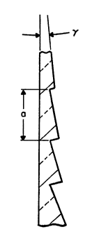
Figure 3A shows a cross-sectional view of an upper portion
20 of one of the series of concpntric zones of the ablated lens 4 shown
in Figure 3. The step sizes of the diffraction grating pr~gressi~rely
increase from the top of the lens to the bottom, thereby ~h~nging
the blaze angle ~y, and therefore, the focal point of an order of a
principle ~liffr~ction maxima m, in accordallce with the general5 equation
asin(-2 y) = m~O
Wo 94/17435 ~ 7 8 PCT/US94/00918
wherein ~O is the chosen wavelength and a is the length of the step.
The optical action of a profile step is normally expressed in
terms of the wavelength (~) of some chosen color of light; for
vision purposes this could be green. The action required for a
S bifocal effect would be in the region of 0.5 ~0 although this can
also be expressed as 1.0 ~d where ~\d iS a 'design' wavelength
rather than the utilized wavelength.
Using ~O in this in~t~nce it can be seen that if the uniform
step height ablated if the mask of Figure 1 were used on its own
10 was 1.0 ~O~ then the inflllçnce of Figure 2 is to reduce this step
height to a fractional value which changes for different regions of
the optical area.
This action is also dependant on the refractive indices of the
ççnt m~ttori~l~ but for simplicity, 'step height' is here taken to
15 mean the optical action of the step so that a 'step height' of ~0 has
a nominal full diffraction çfficiçncy.
For eY~mple, the u~-ifollll change of Figure 2 could give a
zero step height at the top and 1.0 ~0 step height at the bottom.
Around each zone the step height would change in a cyclic f~chion.
20 Taking Figure 4 as ~e,fining the region of the lens in terms of polar
coor~ es, i.e. in~ ting a particular point by radius 'r' and angle
~e~ be~wæn O degrees and 360 degrees, the effect of the wedge
filter described in Figure 2 would be a step height for the outer
zones (r large) which varies from 0 to 1 )~O while the step height for
25 the inner zones (r small) would vary about the same mean value but
by a smaller amount. Figure 5 shows the general effect with the
Wo 94/17435 21~ 0 ~ ~ ~ PCT/uSs4/009l8
full line representing the outer zones and the broken line the inner
zones, the maximum step height being at 270 degrees, i.e. towards
the bottom of the lens, and the minimum step height being at 90
degrees, i.e. towards the top of the lens. The mathematical
5 description could be:
h = r (1 + sin e)
2R
where h is the height of the step, r is the zone radius, R is the
maximum zone radius and e the orient~tion angle as defined in
10 Figure 4.
Such a smoothly generated wedge effect is shown
diagr~mm~ti~lly in Figure 6 where the circles in~ ting the zone
edges have been thick~ned in the region where the step height is
greater. Figure 6 shows that a lens placed on the eye so that the
15 pupil is in position A will view the outside world via mainly low
step height zones and will see a strong in-focus image for distant
objects. If the lens is repositioned on the eye (by the eye looking
downwards, for instance), the pupil has an effective position given
by B in Figure 6. It is now viewing via a region of the lens where
20 the step height is large and will see a strong in-focus image for
nearer objects.
Figure 7 gives an in~ic~tion of the strength of the image
light in terms of rays but this is a purely s~Pm~tic diagram as the
~liffr~tive effects, particularly in the central region with a more
25 even division of the images, cannot be e,~lessed in terms of rays.
Wo 94/17435 PCT/US94/00918
2150478
- However, for appreciable pupil sizes covering 3 to 4 zones of the
diffractive pattern, these rays give a r~rese~-t~tive in~lplelation.
Figure 7 is an effective vertical section through a lens as illll~tr~t~d
in Figure 6, i.e. having greater step heights towards the bottom of
S the lens and smaller step heights towards the top. The rliffr~ted
'rays' passing through the bottom par~ of the lens are therefore of
greater intensity than the non-diffracted (or zero order) rays passing
through that part. Looking through the bottom part of the lens
therefore gives a near image N (produced by diffraction) of greater
10 intensity than the zero order image F. Conversely, the
non--liffr~cted (or zero order) rays passing through the upper part
of the lens are of greater intensity than the diffr~cted 'rays' passing
through the upper part and therefore looking through the upper part
of the lens gives a far image F (to which the non-diffracted rays are
15 refr~t~d) of greater intensity than the near image N.
Figure 8 sçht-m~tically shows a lens having concçntric zones
providing a diffractive effect additional to any refractive effect of
the lens. The step height of the zones is ullirolln (but relatively
low) where the zones are in~ tyl by broken line but in a 'D'
20 shaped segmPnt C the step height is graded as previously discussed
so that it increases gradually from the top of the segment (which is
subst~nti~lly hori70nt~l) to the bottom. Hence, as previously
eYrl~ined, a greater intensity near image is seen by looking through
the lower part of the segment C than through its upper part of
25 looking through other regions of the lens where the far image has
greater intensity.
Wo 94/17435 PCT/US94/00918
2l5~78
-14-
Usually, the multifocal lenses produced in accordance with
the invention will have a refractive power attributable to the general
curvature of the front and back surfaces and the refractive index of
the lens m~tt-.ri~l The concentric zones provide 'add-on' or
S 'subtractive' power compa~ed with the refractive power of the lens.
In order to operate satisfactorily, a lens such as shown in Figures 6
or 8 will need to be t)rient~ted in the appl~liate way on the
cornea. This can be achieved, e.g. by providing a ballast on one
side of the lens, to ensure that the desired area for near vision
comes to rest p,eferenlially on the lower part of the cornea. A
b~ cted lens blank (or a lens blank having other orient~tion means)
and having the desired refractive power for distant vision for a
particular patient is conveniently used as the lens 4 (see Figure 3)
in a laser ablative method of forming a lens with non-unifoln
diffractive power in accordallce with this invention.
Methods of pl~aling b~ cted lenses are well known in the
art. For example, they are described in the book by Stein et al
entitled "Fitting Guide for Rigid and Soft Contact Lenses, published
by The C.V. Mosby Company, St. Louis, Missouri (1990), pages
319 et seq. In addition, reference may be made to the following
US patents for details of m~nuf~ctme of such lenses, viz: US Patent
No. 4,407,766; US Patent No. 4,642,112; US Patent No.
5,009,497; US Patent No. 5,009,497; US Patent No. 5,100,226
and US Patent No. 5,198,844.
In an alternative version of a lens of the type shown in
Figure 8, the step height may be unifo~ln throughout the segment C
but higher than the uniform step height over the rem~in~ler of the
WO 94/17435 PCT/US94/00918
215047~
-15-
- lens. With this arrangement looking anywhere through the
segmt-nt C would give a near image of greater intensity than
looking anywhere else through the lens to give a far image of
greater intensity.
However, sudden changes in step height may be undesirable
and it may be preferable to give a progressive change. Figure 9
shows a localized step height variation depicted on the polar
coordinate basis previously mentioned. For the outer zones
(indir~ted by full line) of the lens the step height is very low over
the O degrees and 180 degrees region but gradually increases after
180 degrees to a maximum fl~ttened peak sp~nning the 270 degrees
area (i.e. the bottom part of the lens) and then gradually decreases
back to the very low value at 360 degrees/O degrees. The inner
zones (indicated by broken line) of the lens have a step height
which follows a similar, but less pronounced, ~r~g.e~ e gr~d~tion
so that their maximum step height at 270 degrees (i.e. towards the
bottom of the lens) is less tnan that of the outer zones and their
minimum step height from about O degrees to 180 degrees (i.e. in
the upper part of the lens is greater than that of the outer zones).
It will be appreciated that in Figure 9, and also in Figure 5,
for ease of illustration the outer zones' step height is represen~ed by
a single full line and the inner zones' step height is represented by
a single broken line. In pr~ti~e, of course, there may be a
progressive change in step height from the innermost zone to the
outermost zone so that Figures 9 and 5 would, if properly
r~,ese.~ting the full situation, have a number of step height lines
corresponding to the number of zones. For convenience, however,
.
Wo 94/17435 - PCT/USg4/00918
~lso~8
-16-
the full line and broken line shown can be considered as
represt~nting the outermost and innermost zone step height
respectively.
In the particular embodiment~ and examples specifically
5 described above it is generally envisaged that the used order of
iffracti~n is first order and the diffractive power is positive, i.e.
the + 1 order. It will be understood however, that the diffractive
power could be negative, e.g. the -1 order could be used, or other
orders, whether positive or negative could be used. Negative
10 diffractive power could effectively subtract from positive refractive
power of the basic lens so that the refractive power gives a near
image and rliffr~ctinn provides a far image. Usually, the described
wedge effect would then be reversed so that the more intense
diffraction occurs towards the top of the lens to give a strong image
15 of near objects being given through the lower part of the lens by
more intense refraction.
It will further be understood that while the diffractive action
is preferably achieved by the use of concçntric zones having
a~lu~.iate surface relief step heights giving the required different
20 intçn~iti~s or efficienci~s of r~iffr~tion, it could ~lt~ tively be
achieved by the use of refractive index variations in the m~teri~l of
the lens which give the required image differentiation when viewed
through dirrel~llt parts of the lens. This can be achieved by
conventional means such as varying the monomer composition
25 through a layer and polymeri7ing before diffusion effects offset the
variable composition. As is also conventionally known, a more
viscous composition may be helpful in reducing diffusion.
Wo 94/17435 pcrlus94/00918
:
21 ~478
Furthermore, reference can be made to Summerville, Plastic
Contact Lens, Noyes Data Corporation, Park Ridge, New Jersey
(1972), which discloses at pages 69-71 the fusion of m~ttori~ of
different refractive index.
Although lenses in acco~ance with the invention are
conveniently pl~a,~d by the laser ablative method described
above, an alternative method of production involves the use of a
co,,,pu~er-controlled lathe. Such a lathe may operate to position a
cutter in accordance with signals derived in the manner that Figures
5 and 9 have been derived from a co",l,u~ stored analogue of the
masks 1 and 2, shown in Figures 1, 2 and 3.
The lenses of the present invention may be hard (e.g. gas
permeable lenses) or soft, e.g. hydrogel lenses, the ch~o-mic~
constitution of which is well known in the art.