Language selection

Search

Patent 2151173 Summary

Third-party information liability

Some of the information on this Web page has been provided by external sources. The Government of Canada is not responsible for the accuracy, reliability or currency of the information supplied by external sources. Users wishing to rely upon this information should consult directly with the source of the information. Content provided by external sources is not subject to official languages, privacy and accessibility requirements.

Claims and Abstract availability

Any discrepancies in the text and image of the Claims and Abstract are due to differing posting times. Text of the Claims and Abstract are posted:

  • At the time the application is open to public inspection;
  • At the time of issue of the patent (grant).
(12) Patent Application: (11) CA 2151173
(54) English Title: DEVICE FOR SEALING AN ANNULAR SPACE
(54) French Title: DISPOSITIF PERMETTANT D'OBTURER DE FACON ETANCHE UN ESPACE ANNULAIRE
Status: Dead
Bibliographic Data
(51) International Patent Classification (IPC):
  • F16J 15/02 (2006.01)
  • F16L 21/02 (2006.01)
(72) Inventors :
  • EKHOLM, KENNETH (Sweden)
(73) Owners :
  • FORSHEDA AB (Not Available)
(71) Applicants :
(74) Agent: MARKS & CLERK
(74) Associate agent:
(45) Issued:
(22) Filed Date: 1995-06-07
(41) Open to Public Inspection: 1995-12-09
Availability of licence: N/A
(25) Language of filing: English

Patent Cooperation Treaty (PCT): No

(30) Application Priority Data:
Application No. Country/Territory Date
9402010-4 Sweden 1994-06-08
9402752-1 Sweden 1994-08-18

Abstracts

English Abstract


A device for sealing a space between an annular wall defining an
opening and a pipe end portion introduced into the opening consists
of a sleeve (2) having at one end thereof a flange (4) for restrict-
ing the introduction of the sleeve into the opening and having at
its other end a flange (6) for restricting the introduction of the
pipe end portion into the sleeve.


Claims

Note: Claims are shown in the official language in which they were submitted.


C L A I M S

1. A device for sealing a space between an annular wall (46; 144),
defining an opening (48; 150), and a pipe end portion (44; 146)
introduced into the opening, said device comprising a sleeve (2;
102) consisting of rubber-elastic material and adapted by its outer
surface sealingly to engage the annular wall and by its inner
surface sealingly to engage the pipe end portion introduced into the
opening, c h a r a c t e r i z e d in that the sleeve (2; 102) has
at its one end an outwardly directed flange (10; 106) for restrict-
ing the introduction of the sleeve into the opening (48; 150) and
has at its other end an inwardly directed flange (6; 104) for
restricting the introduction of the pipe end portion (44; 146) into
the sleeve (2; 102).

2. A device as claimed in claim 1, c h a r a c t e r i z e d in
that the inwardly directed flange (6) for restricting the introduc-
tion of the pipe end portion (44) into the sleeve (2) has a stop
surface (14) adapted to engage the end surface of the pipe end
portion and forming with the axis of the sleeve an angle which is
smaller than 90° and preferably amounts to about 70°.

3. A device as claimed in claim 1, c h a r a c t e r i z e d in
that the outwardly directed flange (106) for restricting the
introduction of the sleeve (102) into the opening (150) has a stop
surface (114) adapted to engage a surface surrounding the opening
and forming with the axis of the sleeve an angle which is smaller
than 90° and preferably amounts to about 70°.

4. A device as claimed in any of the preceding claims,
c h a r a c t e r i z e d in that the flanges (4; 104; 6; 106)
taper in the direction of their free edges.

5. A device as claimed in any of the preceding claims,
c h a r a c t e r i z e d in that the sleeve (2; 102) has between
its ends at least one peripheral, radially directed sealing lip (26;
126).

6. A device as claimed in claim 5, c h a r a c t e r i z e d in
that the sleeve (2; 102) has two peripheral, radially directed


sealing lips (26, 52) which are positioned at a small axial distance
from each other.

7. A device as claimed in any of the preceding claims,
c h a r a c t e r i z e d in that the sleeve (2; 102) has axially
inside one of the flanges (6; 106) a peripheral support bead (32;
102) extending in the same radial direction as the flange.

8. A device as claimed in claim 7, c h a r a c t e r i z e d in
that the support bead (32; 132) has a cylindrical support surface
(38; 138).

9. A device as claimed in claim 8, c h a r a c t e r i z e d in
that the support bead (32; 132) has increasing width in direction of
its base.

10. A device as claimed in claim 7 or 8, c h a r a c t e r i z e d
in that the side surface of the support bead (32; 132) facing said
one flange (6; 106) forms an angle of about 60° with the axis of the
sleeve.

11. A device as claimed in any of claims 7 - 10, c h a r a c -
t e r i z e d in that the side surface (34; 134) of the support
bead (32; 132) turned from said one flange (6; 106) forms an angle
of about 45° with the axis of the sleeve.

12. A device as claimed in any of the preceding claims,
c h a r a c t e r i z e d in that the sleeve has at its one end a
radially directed, peripheral support strip (20; 120).

13. A device as claimed in claim 11, c h a r a c t e r i z e d in
that the support strip (20; 120) has a sharp edge and is defined by
side surfaces (22, 24; 122, 124) forming angles with the axis of the
sleeve less than 45°.

14. A device as claimed in claim 5, c h a r a c t e r i z e d in
that the sleeve has peripheral ridges (40, 42; 140, 142) at its
surface opposite to the sealing lip (26; 126).

15. A device as claimed in claim 14, c h a r a c t e r i z e d in


that the ridges are arranged within surface portions which are
positioned radially opposite to the sealing lip (26; 126) or the
sealing lips (26, 52; 126) and /or radially outside the peripheral
support bead (32; 132).

16. A device as claimed in any of the preceding claims,
c h a r a c t e r i z e d in that the sleeve (102) forms a support
strip (111) at one end surface thereof.
Description

Note: Descriptions are shown in the official language in which they were submitted.


- ~ 2151173

-


The present invention relates to a device for sealing a space


between an annular wall defining an opening and a pipe end portion


introduced into the opening.


The device according to the invention is of the kind comprising a


sleeve consisting of rubber-elastic material, which is adapted at


its outer surface sealingly to engage the annular wall and at its


inner surface sealingly to engage the outer surface of the pipe end


portion introduced into the opening.


Devices of this kind can be used for example for connecting a


plastic pipe with an opening formed in a well ring or a pipe


consisting of concrete and extending transversely to the axis of the


well ring or the pipe. A device of said kind can be used also for


axially connecting two pipes with each other in the case that one of


the pipes has an outer diameter which is less than the inner


diameter of the other pipe, one of the pipes being constituted by a


plastic pipe and the other pipe being constituted by a concrete


pipe. A device of said kind can be used also for connecting a socket


of a first pipe with a spigot end of a second pipe.


Previously known devices of the kind in question have drawbacks in


respect of the determination of the correct position of the sleeve


in relation to the opening in which the sleeve is positioned and/or


the determination of the position of the pipe end portion introduced


into the opening in relation to the sleeve. Deficiencies in respect


of the determ;n~tions of the correct positions usually result in


deficiencies in respect of the sealing of the space between the wall


of the opening and the pipe end portion introduced into the opening.


The object of the invention is to provide a device for sealing a


space between an annular wall defining an opening and a pipe end


portion introduced into the opening, the device being improved in


the respects mentioned above.


In order to comply with this object the device according to the


invention is characterized in that the sleeve has at one end thereof


an outwardly directed flange for restricting the introduction of the


sleeve into the opening and has at its other end an inwardly


directed flange for restricting the introduction of the pipe end

2151173

portion into the sleeve.

It is preferred that the sleeve of the device according to the
invention has at least one continuous, radially inwardly or
outwardly directed sealing lip and that the sleeve axially inside
one of the flanges has a radially directed, continuous support bead
extending in the same direction as the sealing lip and has at the
end of the sleeve at which the other flange is positioned a radially
directed, continuous support strip extending in the same direction
as the sealing lip and the support bead. As a consequence of the
presence of the support bead and the support strip the sleeve will
take an exactly centered position in relation to the surface engaged
by the sealing lip which in turn secures the correct function of the
sealing lip.
In a preferred embodiment of the device according to the invention
the sleeve has at its surface opposite to the sealing lip continuous
ridges securing the tightness between the sleeve and the annular
wall defining the opening. When using the device according to the
invention for connecting a pipe end portion to an opening of a pipe
or a well ring manufactured from reinforced concrete the ridges also
prevent water from getting into contact with the reinforcing irons
of the concrete pipe or the well ring, which reinforcing irons are
uncovered at the annular wall defining the opening when the opening
is provided.

The invention is described in the following with reference to the
accompanying drawings.

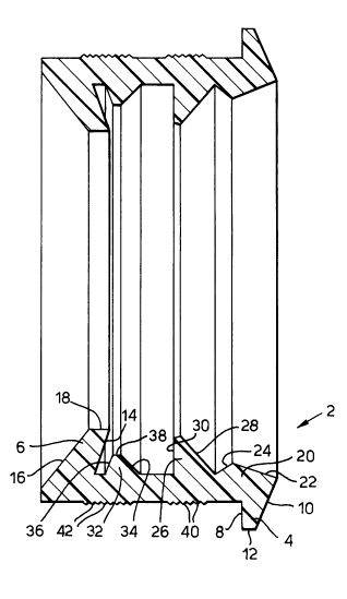
Fig. 1 is an axial section of a first embodiment of a device
according to the invention.

Fig. 2 is a section of a joint established between a pipe end
portion and an opening of a wall of for example a well ring
consisting of concrete, provided by means of the device shown in
Fig. 1.

Fig. 3 is an axial section corresponding to Fig. 1 of a modified
embodiment of the device according to the invention.


2151173

Fig. 4 is an axial section corresponding to Figs. 1 and 3 of a
further modified embodiment of the device according to the inven-
tion.

Fig. 5 is an axial section of a joint established by means of the
device according to the invention shown in Fig. 3, the joint being
provided between the spigot end of an upwardly extending pipe end
portion and a socket of a pipe end portion placed thereon.

The device according to the invention shown in Fig. 1 is constituted
by a sleeve 2 consisting of rubber-elastic material having at one
end an outwardly directed flange 4 and at its other end an inwardly
directed flange 6. The outwardly directed flange 4 has a stop
surface 8 forming a right angle with the axis of the sleeve 2. The
side surface 10 of the flange 4, opposite to the stop surface 8 is
inclined in such a way that the flange 4 tapers outwardly. The
flange 4 is at its outer free edge surface defined by a cylindrical
surface portion 12.

The inwardly directed flange 6 has a stop surface 14 forming an
angle of about 70 with the axis of the sleeve. The side surface 16
of the flange 6, opposite from the stop surface 14 forms a smaller
angle with the axis of the sleeve than the stop surface 14 which
means that the flange 6 tapers towards the interior of the sleeve.
At its inner, free edge portion the flange 6 is defined by a
cylindrical surface portion 18.

At the end at which the outwardly directed flange 4 is positioned
the sleeve 2 has at its inner surface an inwardly directed support
strip 20 defined by two inclined side surfaces 22 and 24 connecting
with each other at an inner, peripheral edge of the support strip
20. The surface 22 forms a conical entering surface facilitating the
introduction of a pipe end portion into the sleeve 2.

Axially inside the support strip 20 the sleeve has an inwardly
directed sealing lip 26 which at the side facing the support strip
20 is defined by an inclined surface 28 forming an angle with the
axis of the sleeve of about 55 while the opposite side surface 30
of the sealing lip 26 forms a substantially right angle with the
axis of the sleeve.

- ` 215117~


Between the sealing lip 26 and the inwardly directed flange 6 the
sleeve has an inwardly directed support bead 32 defined by a side
surface 34 facing the sealing lip 26 and forming an angle with the
axis of the sleeve of about 45 and by a side surface 36 facing the
inwardly directed flange 6 and forming an angle of about 60 with the
axis of the sleeve. At its inner free edge the support bead 32 has
a cylindrical surface portion 38.

The sleeve 2 is at its outer surface formed with peripheral ridges
40 and 42. The ridges 40 are arranged within a portion of the sleeve
2, which is positioned radially outside the sealing lip 26 while the
ridges 42 are arranged within a portion of the sleeve, which is
positioned radially outside the support bead 32.

Fig. 2 illustrates the use of the sleeve 2 shown in Fig. 1 for
connecting an end portion 44 of a plastic pipe with an opening 48
defined by a wall 46, the opening being formed in a well ring 50 or
the like consisting of concrete. The sleeve 2 is positioned in the
space between the wall 46 and the outer surface 52 of the pipe end
portion 44 and engages by means of the stop surface 8 of the
outwardly directed flange 4 the outer surface of the well ring 50
surrounding the opening 48. This provides for a correct and exact
determ;n~tion of the position of the sleeve 2 in relation to the
well ring 50.
When the pipe end portion 44 is introduced into the sleeve 2 the
pipe end portion is guided into a centered position by the surface
22 of the support bead 20. During the continuing displacement of the
pipe end portion 44 into the sleeve 2 the end surface of the pipe
end portion engages the lip 26 which is folded to its sealing
position as shown in Fig. 2. At the same time the engagement of the
pipe end portion 44 with the sealing lip 26 provides for a compres-
sion of the sleeve 2 at the portion of the sleeve 2 positioned
radially outside the sealing lip 26 providing that the ridges 40 are
sealingly forced against the wall 46 of the well ring 50. The
continuing displacement of the pipe end portion 44 into the sleeve
2 provides that the end of the pipe end portion 44 engages the
support bead 32 in turn causing a radial compression of the sleeve
2 in the area of the support bead 32 and an accompanying sealing
pressure of the ridges 42 against the wall 46 of the well ring 50.

215117~

When the end surface of the pipe end portion 44 hits the stop
surface 14 of the inwardly directed flange 6 the pipe end portion 44
is defined with regard to its correct position in relation to the
well ring 50.


In the position shown in Fig. 2 the pipe end portion 44 is supported
in the centered position in the sleeve by the support strip 20 and
by the support bead 32 providing that the sealing lip 26 is in a
correct and efficient sealing position around the whole sleeve 2.
The ridges 40 and 42 efficiently prevent leakage between the sleeve
2 and the wall 46 of the well ring 50 and also prevent liquid from
contacting such reinforcement irons (not shown) which are exposed
when the opening 48 is bored or is in any other way provided in the
concrete material of the well ring 50.

In Fig. 3 there is shown a modified embodiment of the sleeve-shaped
device according to the invention. The sleeve shown in Fig. 3
differs from the sleeve according to Fig. 1 in the respect that it
has less wall thickness then the sleeve according to Fig. 1 and that
it is provided with a further radially inwardly directed sealing lip
52. The rest of the parts of the sleeve shown in Fig. 3 corresponds
to the design of the sleeve according to Fig. 1 and are designated
with the same reference numerals as in Fig. 1 with the addition of
~an. The sleeve according to Fig. 3 is intended for connecting a
pipe end portion with an opening, wherein the space between the wall
of the opening and the outer surface of the pipe end portion is
smaller.

Also the device according to the invention shown in Fig. 4 is
constituted by a sleeve 102 consisting of rubber-elastic material.
At one end the sleeve has an inwardly directed flange 104 and at its
other end the sleeve has an outwardly directed flange 106. The
inwardly directed flange 104 has a stop surface 108 forming a right
angle with the axis of the sleeve 102. The side surface 110 of the
inwardly directed flange 104 opposite to the stop surface 108 is
inclined in such a way that the flange 104 tapers inwardly and forms
at the upper edge of the sleeve 102 an upwardly directed continuous
support strip 111. The flange 104 is at its inner free edge surface
defined by a cylindrical surface portion 112.

21~1173
_

The outwardly directed flange 106 has a stop surface 114 forming an
angle with the axis of the sleeve of about 70. The side surface 116
of the flange 106 opposite from the stop surface 114 forms a smaller
angle with the axis of the sleeve than the stop surface 114 which
means that the flange 106 tapers in the radial direction outwardly.
The flange 106 is at its outer free edge surface defined by a
cylindrical surface portion 118.

At its outer surface the sleeve 102 has at the end at which the
inwardly directed flange 104 is positioned an outwardly directed
support strip 120 defined by two inclined side surfaces 122 and 124
connecting with each other at an outer, peripherally extending
continuous edge of the support strip 120. The surface 122 forms a
conical entering surface when a socket or a pipe end portion is
pushed over the sleeve 102.

Axially inside the support strip 120 the sleeve has an outwardly
directed sealing lip 126 which towards the support strip 120 is
defined by an inclined surface 128 forming an angle with the axis of
the sleeve of about 55 while the opposite side surface 130 of the
sealing lip 126 forms substantially right angle with the axis of the
sleeve.

Between the sealing lip 126 and the outwardly directed flange 106
the sleeve has an outwardly directed support bead 132 defined by a
side surface 134 facing the sealing lip 126 and forming an angle of
about 45 with the axis of the sleeve and by an outwardly facing
cylindrical guiding surface 136.

At its inner surface the sleeve 102 is formed with continuous ridges
140 and 142. The ridges 140 are arranged within a portion of a
sleeve 102 positioned radially inside the sealing lip 126 while the
ridges 142 are arranged within a portion of the sleeve positioned
radially inside the support bead 132.
In Fig. 5 there is shown the use of the sleeve 102 shown in Fig. 4
for connecting a socket 144 of a concrete pipe with a spigot end 146
of an upwardly directed concrete pipe. The pipe provided with the
socket 144 is placed on and rests on the concrete pipe provided with
the spigot end 146, and the sleeve 102 is arranged in the space

- ` 2151173 `
-


. 7

between the cylindrical surface 150 and inner surface 152 of the
socket 144 and the cylindrical outer surface 154 and the end surface
156 of the spigot end 146.

After the sleeve 102 has been positioned on the spigot end 146 with
the inner surface engaging the cylindrical outer surface 154 of the
spigot end and the surface 108 of the flange 104 contacting the end
surface 156 the pipe provided with the socket 144 is lowered towards
the pipe end portion 46, the socket 144 being guided over the sleeve
10102 to a centered position by the engagement with the surface 122 of
the support strip 120. At the continuing displacement of the socket
144 downwardly over the sleeve 102 the socket 144 engages the lip
126 at its surface 150 folding the lip to the sealing portion as
shown in Fig. 5. At the same time the engagement of the socket 144
15with the sealing lip 126 establishes a compression of the sleeve 102
at the portion thereof positioned radially inside the sealing lip
126 providing that the ridges 140 are sealingly forced against the
wall 154 of the spigot end 146. When the socket 144 is displaced
over the sleeve 102 the inner surface 152 of the socket will engage
the support strip 111 which means that the inwardly directed flange
104 will be compressed between the surface 152 of the socket and the
surface 156 of the spigot end until the pipe provided with the
socket 144 is as a whole supported by the pipe provided with the
spigot end 146 through the flange 104 of the sleeve 102.
The invention can be modified within the scope of the following
claims.


Representative Drawing
A single figure which represents the drawing illustrating the invention.
Administrative Status

For a clearer understanding of the status of the application/patent presented on this page, the site Disclaimer , as well as the definitions for Patent , Administrative Status , Maintenance Fee  and Payment History  should be consulted.

Administrative Status

Title Date
Forecasted Issue Date Unavailable
(22) Filed 1995-06-07
(41) Open to Public Inspection 1995-12-09
Dead Application 2002-06-07

Abandonment History

Abandonment Date Reason Reinstatement Date
2001-06-07 FAILURE TO PAY APPLICATION MAINTENANCE FEE

Payment History

Fee Type Anniversary Year Due Date Amount Paid Paid Date
Application Fee $0.00 1995-06-07
Registration of a document - section 124 $0.00 1996-01-25
Maintenance Fee - Application - New Act 2 1997-06-09 $100.00 1997-05-30
Maintenance Fee - Application - New Act 3 1998-06-08 $100.00 1998-05-28
Maintenance Fee - Application - New Act 4 1999-06-07 $100.00 1999-06-02
Maintenance Fee - Application - New Act 5 2000-06-07 $150.00 2000-05-25
Owners on Record

Note: Records showing the ownership history in alphabetical order.

Current Owners on Record
FORSHEDA AB
Past Owners on Record
EKHOLM, KENNETH
Past Owners that do not appear in the "Owners on Record" listing will appear in other documentation within the application.
Documents

To view selected files, please enter reCAPTCHA code :


To view images, click a link in the Document Description column. To download the documents, select one or more checkboxes in the first column and then click the "Download Selected in PDF format (Zip Archive)" or the "Download Selected as Single PDF" button.

List of published and non-published patent-specific documents on the CPD .

If you have any difficulty accessing content, you can call the Client Service Centre at 1-866-997-1936 or send them an e-mail at CIPO Client Service Centre.


Document
Description 
Date
(yyyy-mm-dd) 
Number of pages   Size of Image (KB) 
Abstract 1995-12-09 1 11
Cover Page 1996-07-11 1 16
Description 1995-12-09 7 359
Claims 1995-12-09 3 97
Drawings 1995-12-09 4 90
Representative Drawing 1999-07-14 1 13