Note: Descriptions are shown in the official language in which they were submitted.
21~.12~~
AN INSERT FOR RELEASABLY RETAINING CUTTING MEANS
IN A GROUND DRILL
Field of the Invention
This invention relates to a system for in situ replacement
of cutting means for a ground drill, and in particular,
though not exclusively, to a system for the in situ
replacement of drill bits and/or reamers of core sampling
drills.
Bac3cground of the Invention
In ground drilling it is customary to detachably fix a
drill bit to a lower end of a drill string of a ground
drill and rotate the drill string to effect drilling of a
hole in the ground by the drill bit. A reamer is usually
connected between the lower end of the drill string and the
drill bit to ream the circumferential wall of a hole being
drilled. The drill string is formed by screwing individual
drill rods together. Drill rods usually come in fixed
lengths of 1.5, 3 or 6 metres. As the drill progresses
into the ground additional drill rods are screwed into the
upper end drill string.
During drilling it will be necessary to replace the drill
bit and reamer either as a result of dulling of the drill
bit or due to variations in the sub strata. Although .the
drill bit must be replaced more often (usually at least six
times more often) than the reamer.
In order to replace a drill bit or reamer the entire drill
string must be pulled out of the ground rod by rod, the
drill bit replaced, and the drill string reassembled, rod
by rod as it is relowered into the ground to continue
drilling. The need to fully withdraw, disassemble and
reassemble the drill string when changing the drill
bit/reamer is a slow and costly exercise, with the cost
2 ~ ~ ~ ~ r
- 2 -
increasing as hole depth increases and the drill string
becomes longer.
Several attempts have previously been made to overcome this
problem at least insofar as drill bits are concerned by use
of retractable drill bits which releasably engage the lower
end of the drill string and can be disengaged and retracted
through the drill string for changing while the drill
string remains in situ, thereby avoiding the need to
withdraw the drill string from the hole. However, these
attempts have not proven to be commercially successful for
various reasons including: being extremely complicated in
design or application thereby resulting in a large number
of failure modes and/or being to costly to manufacture or
maintain in an operational state; being prone to fouling
due to drilling fluid and contaminants burring or j amming
segments of the drill bit; misalignment of drill bit
segments upon engagement with the drill string; reduction
in diameter of the core sample due to fixing of the drill
bit to an inner tube of the drill string; reduction in
penetration rate; and breaking of individual segments of
the drill bit.
_Summary of the Invention
It is an object of the present invention to provide a
system for in situ replacement of drill bits and/or reamers
of a ground drill which attempts to overcome at least one
of the above-described deficiencies in the prior art.
According to the present invention there is provided a
system for in situ replacement of cutting means of a ground
drill where the cutting means is composed of a plurality of
segments, said system comprising:
a tubular member adapted for connection to a
lower end of said ground drill, said tubular member
provided with seating means formed circumferentially about
an inner wall of said tubular member for seating said
segments in a cutting position in which said segments can
contact the ground;
a substantially cylindrical insert retained in
said member, said insert being moveable between an
installation position in which said insert locates said
segments in said seating means and retains said segments in
said cu~t~.ng position between said insert and said member
and, a retrieval position in which said insert is retracted
to release said segments from between said insert and said
member whereby said segments can be retrieved for
replacement.
Advantageously said seating means comprises a series of
tapered and flat surfaces formed on said inner
circumferential wall of said member.
Preferably said cutting means is a drill bit and said
segments are bit segments, said bit segments provided with
a series of tapered and flat surfaces which face said
series of surfaces formed on said member when said bit
segments are retained between said insert and said member,
each of said series of surfaces configured and juxtaposed
so that said bit segments can slide relative to said member
when in said cutting position in response to said drill
being lifted from and lowered onto the bottom of a hole
being drilled by said drill.
Preferably, said series of surfaces are further configured
and juxtaposed so that a lower end of said bit segments can
flex in a radial direction away from a central longitudina7_
axis of said member to abut said inner circumferential wall
of said member when said drzJ~l is used as a core sampling
dxi.ll and lifted ~xom the bottom of said ho~.e to break a
core sample.
Preferably said sealing means comprises a land extending
circumferentially about said inner circumferent~.al wall of
~. w"-' ~'
- 4 -
said member for engaging an upper end of each segment, said
land disposed adjacent and above an upper most one of said
tapered and level surfaces formed on said member.
Preferably said system further comprises a tool dimensioned
S to travel through said ground drill and into said member
for transporting said segments to and from said member,
said tool being switchable between an installation mode in
which segments are loaded onto said tool for installation
in said member and a retrieval mode in which said tool is
devoid of segments for retrieval of segments previously
installed in said member; said tool provided with engaging
means for engaging said insert whereby said tool can move
said insert between said installation position and said
retrieval position,
new segments can be installed by switching said
tool to said installation mode and lowering said tool into
said drill to a position where said position of said tool
extends beyond the lower end of said insert and said
engaging means engages said insert wherein further downward
movement of said tool moves said insert to said
installation position in which said insert locates said
segments in said seating means and retains said .segments in
said cutting position between said insert and said member
whereafter said tool can be withdrawn to allow drilling to
proceed.
Preferably, said tool comprises installation latching means
and retrieval latching means for engaging said insert, said
installation means being operable and said retrieval
latching means being inoperable when said tool is in said
installation mode and both said installation and said
retrieval latching means being operable when said tool is
in said retrieval mode, wherein, said installation means
can engage said insert when said tool is lowered into said
drill and said retrieval latching means can engage said
insert when said tool is pulled upwardly a first distance
~e~~~ J
so as to pull said insert upwardly said first distance,
said retrieval latching means being disengaged
automatically from said insert upon pulling said tool
upwardly beyond said first distance.
Preferably said tool includes mode selecting means for
switching said tool between said installation and retrieval
modes, said mode switching means comprising a selector
sleeve slidably and rotatably mounted on a body portion of
said tool, and provided with installation apertures and
retrieval apertures through which said installation
latching means and said retrieval latching means can
protrude respectively, wherein said selector sleeve can be
rotated from a first position corresponding to the
installation mode in which said installation apertures
over-lie said installation latching means and said
retrieval apertures are radially offset relative to said
retrieval latching means and, a second position
corresponding to said retrieval mode in which said
installation apertures and said retrieval apertures over-
lie said installation latching means and said retrieval
latching means. respectively._ .
Preferably said installation latching means engages said
insert by way of abutment with one or more abutment
surfaces formed near an upper end of said insert.
Preferably said upper end of said insert is profiled in a
manner so that when said installation latching means
contacts said upper end, said tool can be rotated about its
longitudinal axis to align said tool, insert and segments
so that said segments can be installed in or retrieved from
between said insert and said member.
Preferably said insert is provided with a first detent for
engaging said retrieval latching means and said system
further includes means for disengaging said retrieval
- 6 -
latching means from said first detent when said tool is
pulled upwardly beyond said first distance.
Preferably said disengaging means comprises a tapered
surface for compressing said retrieval latching means.
Preferably said tool comprises carrier means onto which
said segments can be loaded for carrying said segments to
and from said member, and wherein said tool is operable to
cause said segments to slide relative to said tool body
when said tool engages said insert whereby an upper end of
said segments can extend laterally of said tool to engage
said seating means and said'insert.
Preferably said carrier means comprises a cradle about
which said segments are radially spaced, said cradle being
slidable relative to a portion of said tool when said tool
is in said installation mode and said tool engages said
insert, whereby upon relative sliding movement of said
cradle and said portion of said tool, said upper end of the
segments extend laterally of said tool for engagement by
said sea.ting.means.and.said insert.
Preferably said system further comprises an elastic band
surrounding said segments for retaining said segments on
said tool, said elastic band acting to bias said segments
toward a central longitudinal axis of said member when said
segments are retained in said cutting position whereby,
during retrieval of said segments, said elastic band
assists in collapsing said segments onto said tool.
Preferably said cradle comprises an elongate shank
extending from a lower tapered end of said body portion of
said tool and being slidably housed within a bore in said
body portion, and biasing means acting to retract said
shank into said bore, wherein, in said installation mode
and prior to engagement of said tool with said insert, said
biasing means is held in compression and said shank extends
from said bore so that the upper ends of said segments rest
on said tapered end and upon engagement of said tool with
said insert, said biasing means is released from
compression thereby retracting said shank into said bore so
that the upper ends of said segments slide along said
tapered end to extend laterally of said tool.
Preferably said selector sleeve operates a second detent
means for holding said biasing means in compression and
wherein said selector sleeve is coupled to said
installation latching means so that when said installation
latching means engages said insert said selector sleeve
slides relative to said tool body to release said second
detent means thereby allowing expansion of said biasing
means and retraction of said shank into said bore.
In an alternate embodiment, the system can be used for in
situ replacement of a reamer of a ground drill where the
reamer is composed of a plurality of separate segments. In
this embodiment, the cradle comprises a plurality of
recesses_ formed in .said tool body, an upper end of each
recess provided with a ramp leading to an outer surface of
the body and, the selector sleeve being provided with a
plurality of apertures which over-lie said segments in both
said installation and retrieval modes with a radially
inwardly directed lip provided at a lower end of each
aperture for abutment with a lower end of each segment,
whereby, when said installation latching means engages said
insert with the tool in the installation mode, the selector
sleeve can slide relative to the tool body so that said
lips push said segments and the upper ends of the segments
slide along said ramps to extend laterally beyond the tool
to engage the seating means and the insert. In this
embodiment, advantageously the seating means comprises a
plurality of cut-outs formed radially about said member
_8_
through which a cutting face of the segments can protrude
to effect cutting of the ground.
In a further embodiment, a combined system is envisaged for
in situ replacement of both a drill bit and a reamer of a
ground drill in which the drill bit comprises a plurality
of bit segments and the reamer comprises a plurality of
reamer segments, the combined system comprising a first
.sub-system for replacement of bit segments and a second
sub-system for replacement of said reamer segments, each
sub-system including a tubular member, and insert in
accordance with a first aspect of this invention wherein
the member of the second sub-system is connected to a lower
end of the drill and the member of the first sub-system is
connected to the member of the second sub-system so that
both the drill bit and reamer can be replaced
simultaneously.
Brief Description of the Drawings
Embodiments of the present invention will now be described
by way of example only, with reference to the accompanying
drawings in which:
Figure 1 is a side elevation view of a first
embodiment of the system disposed within a ground drill;
Figure 2 is a side elevation view of a tool used
in the system shown in Figure 1;
Figure 3 is a longitudinal section view of the
tool shown in Figure 2;
Figure 4a is a side elevation view of a selector
sleeve of the tool shown in Figures 2 and 3;
Figure 4b is a end view of the sleeve shown in
Figure aa;
Figure 4c is a view of an opposite end of the
sleeve shown in Figure 4a;
Figure 4d is a view of Section B-B shown in
Figure 4a;
Figure 4e is a view of Section C-C shown in
2~. ~~.~'
_ g _
Figure 4a;
Figure 4f is a part view of Section A-A shown in
Figure 4b;
Figure 4g is a view of Section D-D shown in
Figure 4a;
Figure 5a is a side elevation view of an insert
used in the system
shown in Figure
1;
Figure 5b is a view of one end of the insert
shown in Figure 5a;
Figure 5c is a view of an opposite end of the
insert shown in Figure 5a;
Figure 6a is a longitudinal section view of a
member used in he system shown in Figure 1;
t
Figure 6b is a view of one end of the member
shown in Figure 6a;
Figure 6c is a view of an opposite end of the
member shown in Figure 6a;
Figure 6d is a view of a lower portion of the
member shown in Figure 6a;
Figure 7a is a side view of a bit segment used
in
the system shown in Figure 1;
Figure 7b is a top view of the bit segment shown
in Figure 6a;
Figure 7c is an end view of the bit segment shown
in Figures 7a an d 7b;
Figure 8a is a top view of a locking clip used
in
the system shown in Figure 1;
Figure 8b is a side view of the locking clip
shown in Figure 6a;
Figure 9 is an enlarged partial section view of
a
lower end of the system;
Figure 10 is a sectional view of an end of the
drill in a drilling
mode with bit
segments locked
in a
cutting position by the insert;
Figure 11 is a view of the drill string shown in
Figure 10 but with
the drill string
pulled upwardly
from a
bottom of a hole being drilled;
- 10 -
Figure 12 is a sectional view of a tool used in a
second embodiment of the present invention;
Figure 13 is a top view of a reamer segment used
in the second embodiment of the invention;
Figure 14 is a partial sectional view of the
second embodiment of the invention where the reamer
segments are held in a cutting position;
Figure 15 is a side view of a transport sleeve
for the system shown in Figure 1; and,
Figure 16 is a side view of a transport sleeve
deadweight for the system shown in Figure 1.
Detailed Description of the Preferred Embodiments
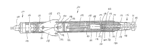
Figure 1 illustrates a first embodiment of a system 10 for
the in situ replacement of cutting means in the form of a
drill bit of a ground drill 12. The drill 12 is composed
of a plurality of interconnected drill rods 14 which
together form a drill string. A standard reamer 16 for
reaming the circumferential wall of a hole being drilled is
screwed to the free end of the lowest rod 14.
The system 10 comprises a number of separate but
interactive components these including a tubular member
taking the form of a drive sub 18 which is adapted for
connection to a lower end of the drill 12, an installation
and retrieval tool 20 dimensioned to travel through the
drill 12 for carrying drill bit segments 22 (refer Figs.
7a, 7b, and 9) to and from the drive sub 18 and, a
substantially cylindrical insert 24 which is slidably
retained within the member 18 between an installation
position in which the insert retains the bit segments 22 in
- 11 -
the drive sub 18 and a retrieval position in which the
insert 24 is retracted to allow the bit segments 22 to
collapse onto the tool 20 for withdrawal from the drill 12.
Referring to Figures 6a and 6d, it can be seen that the
inner circumferential wall 26 at a lower end 28 of the
drive sub 18 is provided with seating means 30 for seating
the bit segments 22. The seating means 30 includes a land
32 extending circumferentially about the inner surface 26
followed, in the downstream direction, with a series of
tapered and flat surfaces and recess 58 formed on the
lowermost one of those surfaces. Specifically, the land 32
is followed by the following sequence of surfaces in the
down stream direction: surface 34 tapering away from a
central longitudinal axis 36 of the drive sub l8; surface
38 extending parallel with axis 36; surface 40 tapering
toward axis 36; surface 42 tapering away from axis 36;
surface 44 extending parallel to axis 36; surface 46
tapering toward axis 36; and surface 48 tapering away from
axis 36 and extending to the longitudinal extremity 50 of
the drive sub 18. Contiguous with surface 48 is a surface
52 tapering away from both axis 36 and extremity 50 and
which leads to outer circumferential surface 54 of the
drive sub 18.
A plurality of drive lugs 56 are provided on surface 46.
Adjacent drive lugs 56 define the recesses 58 in which a
lower end of the bit segments 22 are held during drilling.
As is most evident from Figure 6b, the width of the drive
lugs 56 reduces in the radial direction toward axis 36. A
pair of opposed slots 60 extending parallel to axis 36 are
machined in wall 26 inboard of the ends of the drive sub
18. A locking clip 62 (refer Figures 8a and 8b) is
inserted into an upper end 64 of each slot 60. A lower end
of each locking clip is formed with a surface 65 tapering
toward the inner wall 26 and a spring clip 66 attached near
N L,
,~ . ~ . r~, ~ _~,
- 12 -
an upper end of the clip on a surface opposite the inner
wall 26.
As explained with reference to Figures 7a and 7b, the bit
segments 22 are configured for mating with the seating
means 30 of the drive sub 18. The bit segments comprise a
shank 68 and a crown 70 formed at a lower end of the shank
68 for engaging and cutting the ground. The crown 70
typically comprises a matrix of diamonds and metal. In
use, as ground engaging face 72 of the crown wears away
fresh diamonds are exposed to facilitate cutting.
Side 74 (shown uppermost in Figure 7b) of the bit segments
22 faces the inner surface 26 of the drive sub 18. The
side 74 of shank 68 comprises the following sequence of
surfaces starting from crown 70 (the axis 36 is shown in
phantom for convenient reference in Figure 7a); surface 76
tapering toward axis 36; surface 77 extending parallel to
axis 36; surface 78 tapering away from axis 36; surface 80
tapering toward axis 36; level surface 82 extending
parallel to axis 36; surface 84 tapering away from axis 36;
surface 86 tapering toward axis 36; surface 80 extending
parallel to axis 36. Surface 88 is followed by an abrupt
step 90 which leads to surface 92 tapering toward axis 36
and extending to extremity 94 of the shank 68.
Opposite side 96 of shank 68 comprises the following
sequence of surfaces in the direction from extremity 94 to
crown 70: surface 98 tapering toward axis 36; level surface
100 extending parallel to axis 36; surface 102 tapering
toward axis 36; and level surface 104 extending parallel to
axis 36.
As shown most clearly in Figure 7c, the crown 70 is in the
shape of a sector of an annulus and formed with inner and
outer arcuate faces 106 and 108 respectively, with the
length of face 108 being greater than that of face 106.
- 13 -
The face of the crown 70 opposite cutting face 72 is
provided with the following sequence of surfaces in the
direction from outer fac a 108 to outer face 106: surface
110 extending parallel to cutting face 72; surface 112
5 inclined toward cutting face 72 and terminating adjacent
surface 76 of shank 68; and surface 114 tapering away from
cutting face 72 and terminating at arcuate face 106.
Surfaces 112 and 76 form a V-shaped recess 116 which can
engage the services 48 and 52 of the drive sub 18 (as seen
10 in Figure 10).
Referring to Figures 2-4f, the tool 20 comprises a main
body portion 118 upon which a selector sleeve 120 is
slidably and rotatably retained. An upper end 122 of body
118 is provided with a screw thread for attaching a
15 standard wire line adaptor 124. A pair of opposing
longitudinal grooves (not shown) are machined in body 118
at end 122 for slidably retaining a ring 126. The ring is
provided on its inner circumferential surface with a pair
of protrusions (not shown) which ride in the grooves to
20 allow the ring 126 to slide longitudinally of the body 118.
A spring 128 retained between the wire line adaptor 124 and
ring 126 acts to bias the ring 126 and sleeve 120 away from
end 122. A protrusion 130 is formed on an end of ring 126
adjacent the sleeve 120 for engagement in one of the two
25 mode selector recesses 132, 134 cut in an adjacent end of
the sleeve 120.
Body 118 is provided with an internal cavity 136 which
houses a pair of installation latch dogs 138. Pin 140
extends through one end of both latch dogs 138 and couples
30 the body 118 to the sleeve 120. The pin 140 resides in a
longitudinal slot (not shown) formed in the body 118 and a
transversely extending slot 142 formed in the sleeve 120.
Each end of pin 140 sits on a lip 143 formed about the
periphery of slots 142. This provides a connection between
- 14 -
body 118 and sleeve 120 where the sleeve can slide
longitudinally and rotate relative to the body 118.
A second pin 144 extends parallel to pin 140 and resides in
a longitudinal slot 148 formed in the body 118. Spring 150
connects opposite ends of latch dogs 138 to the pin 144.
The spring 150 biases the latch dogs 138 so as to extend
laterally of body 118 and through apertures or slots 139
(refer Figs. 4A, 4D) cut in sleeve 120. Each latch dog 138
is provided with a bearing face 152 for abutment with the
insert 24.
A pair of retrieval latch dogs 154 similar to the insertion
latch dogs 138 is also provided in the tool 20 on a side of
the latch dogs 138 opposite end 122. However, the
retrieval latch dogs 154 are located in a plane disposed
perpendicular to that containing the insertion latch dogs
138. In addition, the retrieval latch dogs are orientated
in an opposite sense to the insertion latch dogs 138. That
is, ends 156 of retrieval latch dogs 154 are biased by a
spring (not shown) to extend laterally of the body 118 and
through apertures or slots 155 (refer Figures 4a, 4e) cut
in sleeve 120 with opposite ends 158 being held by a pin
160 extending through the body 118. Bearing faces 162 are
formed at ends 156 of the retrieval latch dogs 154 for
engaging the insert 24.
As is most evident from Figures 4d and 4e, the installation
latch dog slots 139 are wider than the retrieval latch dog
slots 155.
A rectangular cavity 164 is formed in the body 118 adjacent
the retrieval latch dogs 154. Extending longitudinally of
one end 166 of the cavity 164 is a hole 168 which
communicates with cylindrical recess 170. Recess 170
extends through a frusto-conical shaped end 172 of the body
118. The cavity 164, hole 168 and recess 170 collectively
- 15 -
form a slideway 174 for a cradle 176 upon which the bit
segments 22 are attained.
The cradle 176 comprises a central bar 178 from which
coaxially extends at one end a threaded stem 180 and
terminates at an opposite end in a stop 182. The stem 180
extends through recess 170 and hole 168 into cavity 164.
The end of the bar 178 adjacent the stem 168 is slidably
received in recess 170. A spring 184 is retained on the
stem 180 between a tension adjustment nut 186 screwed onto
the stem 180 and end 166 of the cavity 164. Opposite ends
188 and 190 of the nut 186, are tapered or bevelled so as
to reduce in thickness radially away from the centre of the
nut 168.
A pair of locking pins (not shown) reside in respective
recesses 192 formed in the body 118. The pins are retained
within their respective recesses 192 by the sleeve 120 and
have an end which can be selectively extended into and
retracted from the recess 164 by virtue of relative
movement of the sleeve 120. Referring to Figure 4f, an
inner circumferential wall 194 of the sleeve 120 is
provided with a circumferential groove 196. When the
sleeve 20 is positioned so that the groove 196 overlies the
recesses 192, the ends of the pins therein can be retracted
from the cavity 164 to allow extension of spring 184.
However, the ends of the pins are held to extend into the
cavity 164 by abutment of the pins with wall 194 when the
sleeve 120 is positioned so that the groove 196 does not
overlie the recesses 192. Under this condition, the pins
abut against nut 186 maintaining the spring 184 in
compression.
When loading the tool 20 to install the bit segments 22,
the segments are disposed radially about the bar 178 with
crowns 70 abuting the stop 182. Surface 98 of each bit
segment 22 rests on the large diameter end of frusto-
iaa Jd_ L.1 ~ ~a
- 16 -
conical end 172 for the body 118. An elastic band 198
encircles the bit segments 22 about respective surfaces 82
to hold the bit segments onto the cradle 176.
A plurality of ridges 200 are provided on the outside
surface of sleeve 120 extending parallel to the length of
the sleeve 120. The ridges 200 are evenly spaced, with
adjacent ridges defining shallow channels 202 through which
a fluid can flow when the tool 20 is lowered through the
drill 12.
Insert 24 (refer Figs. 5a-5c) is provided in the system 10
for expanding the bit segments 22 against the bias of
elastic band 198 and locating the bit segments 22 into a
cutting or drilling position against the inner surface of
drive sub 18.
The insert 24 is in the form of a cylindrical tube having a
pair of opposing peaks 206 extending from an upstream end
204. The sides of each peak slope sharply in the
downstream direction and lead to flats 208 which separate
the peaks 206. A pair of longitudinally extending rails
210 protrude from the outer circumferential surface 212 of
insert 24. The rails 210 ride in the slots 60 in the drive
sub 18. A pair of opposed detents in the form of
longitudinally extending slots 214 (only one shown) are cut
into the insert 24 for engaging the retrieval latch dogs
154. An upstream end of each slot 214 is bevelled so as to
slope toward an inner surface of the insert 214 in the
upstream direction. The end of the sleeve 24 opposite
peaks 206 is provided with a plurality of longitudinally
extending keyways 218. Adjacent keyways 218 are spaced
apart by lugs 220. Waterways 222 are machined along the
length of the inner surface of insert 24. The watenaays
provide a flow path for water used in bit cooling,
lubrication and flushing.
- 17 -
A tool 20' (refer Figure 12) for replacing reamer segments
(refer Figs. 13 and 14) is structurally and functionally
equivalent to the tool 20 used for replacement of drill bit
segments 22. Accordingly, the reference numbers used in
relation to the description of the. tool 20 are also
employed to denote similar features in the tool 20'. A
wireline adaptor 124' is screwed onto upper end 122 of the
tool 20'. Spring 128' interposes the wireline adaptor 124'
and ring 126' . As with tool 20, the ring 126' is able to
slide longitudinally of the tool 20' as provided with a
protrusion 130 for engaging recesses (not shown) cut in an
upper end of sleeve 120'. Installation and retrieval latch
dogs 138' and 154' are identical to those of tool 20. The
essential differences between tool 20' and tool 20 are that
the cradle 176' comprises a plurality of cut-outs 227
formed radially about a lower end of body 118'. An upper
end of each cut-out is provided with a ramp 228 which leads
to the outer surface of body 118'. In addition, sleeve
120' is provided with a plurality of apertures 230 which
overlie the cut-outs 227. A radially inwardly directed lip
232 is provided at the lower end of each aperture 230.
A further difference between tools 20 and 224 is the length
of the slots in which the pins of the installation and
retrieval latch dogs are retained. Specifically, the slots
in tool 20' (see for example slot 148') are much longer
than those of the corresponding slots in tool 20.
A standard overshot attachment 234 is connected to the
lower end of tool 224 for connection with the wireline
adaptor 124 of tool 20. This connection allows the tools
20 and 20' to rotate relative to each other.
Reamer segments 226 are retained in cut-outs 227 when being
installed in or retrieved from the drill 12. Reamer
segments 226 are in the shape of a rectangular prism having
inclined sides. Each segment 226 is mounted on a
~~~'a~~'~~.
- 18 -
rectangular plate 236. Upstanding lips 238 and 240 extend
across the upstream and downstream ends of the plate 326
respectively. Both lip 240 and the upstream end of the
plate 236 are bevelled so as to converge toward each other
in the upstream direction.
The segments 226 are retained in cut-outs 227 by rubber
bands 242 and 244 which encircle plates 236 adjacent the
ends of the corresponding segments 226.
A tubular member in the form of an auxiliary drive sub 18'
is screwed onto the drill for holding the reamer segments
226 in a cutting position. Auxiliary drive sub 18' is
provided with seating means comprising a land 32'
protruding inwardly from an inner circumferential wall of
drive sub 18' and cut-outs 246 (only one shown) having
bevelled edges 248 for seating the bit segments 226. A
recess 250 is cut into the inner surface of the drive sub
18 adjacent the downstream end of each cut-out 246 for
accommodating the lips 238.
Auxiliary insert 24' is retained with auxiliary drive sub
18 for selectively holding the segments 226 in a cutting
position and releasing the segments 226 for replacement.
Insert 24' is essentially the same as insert 24 with the
exception that it does not include the keyways 218 and lugs
220 of insert 24. Tool 20' is used to slide the insert 24'
between an installation position in which the insert 24'
locates and retains the segments 226 in the cutting
position and, a retrieval position in which the insert 24'
is retracted to release the segments so that they can
collapse back onto the tool 226 by action of the elastic
bands 242 and 244.
Referring again to Figure 1, the ground drill 12 is in this
embodiment a core sampling drill such as for example, of
the type manufactured by LONGYEAR. Core sampling drills
- 19 -
typically include a landing ring 252 retained in a lower
end of the drill 12. The landing ring 252 is used to halt
the passage of a conventional core sample barrel 254 (refer
Figures 10 and 11). The top of the core sample barrel 254
rests on the landing ring 252 preventing the core sample
barrel 254 from falling out of the drill 12. The core
sample barrel 254 is used to collect and retain a core
sample of the ground being drilled. Once the core sample
barrel is filled, drilling is stopped, the drill lifted
from the bottom of the hole being drilled to break the core
sample, then the core sample barrel lifted up through the
drill 12 by a wire line 256.
When the system 10 is used for in situ replacement of a
drill bit only, then the conventional core sampling drill
bit (not shown) is replaced with drive sub 18 which
threadingly engages reamer 16. In the event that the
system 10 is also to be used to allow in situ replacement
of the reamer, then the standard reamer 16 is also removed
and replaced with drive sub 18'. Inserts 24 and/or 24' are
always retained within corresponding drive subs 18 and 18'.
Tools 20 and 20' are lowered and retrieved from the drill
12 for installing and retrieving bit segments 22 and 226
respectively. When tools 20 and 20' are removed, standard
core sample barrel 254 can then be lowered into the drill
12 which passes through the inserts 24 and 24' for
receiving a core sample.
The method of operation of the system 10 will now be
described in connection with the replacement of drill bit
segments.
The drive sub 18 is screwed onto the reamer 16 of a
standard core sampling drill. Tool 20 is set to the
installation mode by turning sleeve 120 relative to ring
126 so that the protrusion 130 engages installation mode
selector recess 132. Cradle 176 is extended from body 118
compressing the spring 184 which is held in compression by
- 20 -
locking pins (not shown) having ends extending into the
cavity 164. In this configuration, the installation latch
dogs 138 extend laterally from slots 139 in the sleeve 120.
However, the retrieval latch dogs 154 are not aligned with
slots 155 and are therefore held in a compressed state
within the confines of sleeve 120. Bit segments 22 are
loaded onto the cradle 176 and held in place by elastic
band 198 which contacts the surface 82 of each bit segment
22. Crown 70 of each bit segment abuts stop 182. The
insert 24 is disposed within the drive sub 18 and held
above the seating means 30 by clip 62. The insert 24 is
orientated so that peaks 206 point in the upstream
direction. Rails 210 of the insert 24 ride in slots 60 to
allow the insert 24 to slide along the inside of the drive
sub 18.
Tool 20 is connected to a standard wire line overshot via
the wireline adaptor 124 and inserted into transport sleeve
260 (shown in Figure 15) which compresses the installation
latch dogs 138. Transport sleeve 260 together with tool 20
is then lowered through the centre of the drill 12.
Transport sleeve dead weight 262 (refer Figure 16) can be
attached to an upper end of sleeve 260 to increase the rate
of decent of tool 20. The decent of the transport sleeve
260 is halted by abutment with the landing ring 252.
However, the tool 20 which has an outer diameter smaller
than the inner diameter of the ring 252 continues its
decent. As the tool 20 passes through landing ring 252,
the installation latch dogs 138 are biased by spring 150 to
extend from slots 139 formed in sleeve 120. Bearing faces
152 of latch dogs:.138 contact peaks 206 causing the tool 20
to rotate until a position is reached where the bearing
faces 152 reside on flats 208 separating the peaks 206.
The rotation of the tool 20 ensures correct alignment of
bit segments 22 with recesses 56 of the drive sub 18 and
keyways 218 of the insert 24.
- 21 -
The latch dogs 138 are driven backward a short distance
upon impacting with peaks 206 causing a corresponding
movement in the sleeve 120. This action results in the
groove 196 being located over recesses 192 so that the pins
(not shown) residing therein are retracted from cavity 164
allowing spring 184 to expand. This in turn causes the
cradle 176 to retract into the body 118. Surface 98 of
each bit segment slides along the frusto-conical end 172 to
extend laterally of the body 118 and contact inner wall 22
(refer Figure 9). As tool 120 continues its decent, the
step 90 of shanks 68 engage the land 32 on the drive sub
18.
The continued downward movement of the tool 120 also draws
insert 24 downwards by virtue of the installation latch
dogs 138 bearing on flats 208. When step 90 of each bit
engages land 32 further downward movement of the bit
segments 22 is prevented. The insert 24 collects the
backside 96 of the bit segments and acts to expand the bit
segments.22 outwardly in the radial direction against the
bias of elastic band 198 locating the bit segments into
separate recesses 58. The insert 24 continues to move
downwardly until it reaches the installation position in
which its keyways 218 slide over the bit segments 22 to
retain the bit segments between the drive sub 18. Elastic
band 198 resides in a cavity formed between surface 44 of
the drive sub 18 and surface 82 of the bit segments 22.
Tool 20 can then be withdrawn via the wireline 256 to the
landing ring 252 upon which, installation latch dogs 138
are compressed by being drawn backwards through ring 252.
Tool 20 then re-enters the transport sleeve 260 and both
are completely withdrawn from the drill 12.
The bit segments 22 locked about the drive sub 18 form a
drill bit for cutting the ground. Standard core sample
barrel 254 can then be lowered into the drill 12 via wire
- 22 -
line 256 for holding a core sample of the ground being
drilled. Insert 24 is dimensioned to allow the core sample
barrel 254 (refer Figs. 10 and 11) to pass therethrough.
With the bit segments 22 retained between drive sub 18 and
insert 24 so as to form a drill bit, the drill 12 is
lowered to the bottom of the bore hole being drilled and
rotated to recommence drilling. Referring to Figure 10 as
the bit crowns 70 touch the bottom of the hole, bit
segments 22 are forced to slide backward with surfaces 34,
10 48 and 52 of the drive sub bearing against surfaces 86,
112, and 114 of the bit segments respectively. In this
mode, (drilling mode) steps 90 are spaced above the land
32. The sliding motion of the bit segments is facilitated
by surfaces 77 and 88 of the bit segments, and surface 38
of the drive sub, all of which extend parallel to axis 36.
The arrangement of surfaces on the bit segments 22 and
drive sub 18 transfers the bit weight and internal/external
rotational forces created during drilling to the drive sub
18. Furthermore, this action locks the insert 24 in place
20 by means of a clamping action as the uppermost inside edge
of each bit segment is forced slightly inwardly, against
the outer circumferential wall 212 of the insert 24.
The transfer of forces during drilling between the bit
segments 22 and drive sub 18 are also shown in Figure 10
25 and are described hereinafter. Arrow A shows the direction
of transference of a portion of the string weight from the
bit crown 70 to the drive sub 18 during drilling. This
force is directed in the longitudinal direction of drive
sub 18 and is applied to surfaces 48 and 52. The remainder
30 of string weight is transmitted through surface 86 of each
bit segment to surface 34 of each keyway as shown by Arrow
F in Figure 10. This force also causes the bit segments 22
to move radially inwards so as to provide the clamping
action against insert 24 required during drilling.
~~.~~..
- 23 -
External radial forces acting on face 108 of crowns 70
transferred to the drive sub by surface 52 as shown by
arrow B. These forces are also borne by surfaces 52 and 48
of the drive sub 18. Internal radial forces on the bit
5 crown 70 and drive lugs 56 are transferred to the drive sub
via surface 48 as indicated by arrow C.
During core breaking (shown in Figure 11) when the drill 12
is lifted from the bottom of the borehole, the bit segments
slide relative to the drive sub 18 until steps 90 abut land
10 32, with surfaces 40 and 46 of the drive sub bearing
against surfaces 84 and 78 of the bit segments
respectively. The core sample barrel 254 also exerts a
force against surface 102 of the bit segments 22. This
force is transmitted in a diagonal direction inclined
15 toward the bottom of the bore hole from the bit segments 22
to the drive sub 18 between respective surface pairs 77 and
46; and, 84 and 40 as shown by arrows D, E and G.
A space or gap between surfaces 78 and 46 on the bit
segments 22 and drive sub 18 respectively (shown in Figure
20 10) allows the bit segments 22 to flex radially outwardly
when the core sample barrel 254 exerts a force on the bit
segments 22 during core breaking. This spreads the bit
segments radially away from axis 36 during core breaking
and allows the core sample to be broken from the rock
25 formation being drilled in the conventional manner via a
core sample barrel lifter (not shown).
During drilling, as explained above, the insert 24 locks
the bit segments 22 in place by a clamping action as the
upper most inside edge of each bit segment is forced
30 slightly inwardly against the outer circumferential wall
212 of insert 24.
- 24 -
Rotational drive is rotated from the drive sub 18 to the
bit segments 22 via drive lugs 56.
Bit lubrication and cooling is provided in the conventional
manner with fluid being pumped into the drill 12 and
channelled via internal waterways 222 of insert 24 which
allows the fluid to reach the bit crown 70. However,
cooling at the bit crown 70 is substantially different to
that achieved with standard drill bits. Extremely wide
waterways are automatically provided in the present system
10 by the gaps formed between adjacent bit segments 22.
In conventional drill bits, relatively narrow channels or
grooves are cut in the crown to allow for the passage of
lubricating and cooling fluid. The gaps between the bit
segments 22 in the present embodiment, represent an
increase of between 300 to 600 of the waterway width in
comparison with standard drill bits. Conversely, there is
a substantial reduction in the surface area of the bit
crown 70. This is contrary to standard practice of bit
matrix design. It is believed that the present arrangement
of drill bit segments provides more efficient cutting as
cooling, flushing of contaminants, and lubrication is
achieved more efficiently and at lower pump pressures. The
crown design also affords an increased penetration rate by
virtue of the concentration of the drill weight onto a
smaller cutting area. The extra wide waterways between
adjacent bit segments also negate the problem of bit
waterway blockage and lost circulation caused by burring of
the bit crown or contamination by drill cuttings.
To retrieve and replace bit segments 22, the drill 12 is
initially lifted a short distance off the bottom of the
hole so as to break a core sample from rock formation 264.
The core sample barrel 254 is then removed from the drill
by use of wireline 256 in the conventional manner.
- 25 -
Tool 20 is placed into the retrieval mode by means of a
counter-twist of sleeve 120 so that the retrieval recess
134 engages protrusion 130. This results in slots 155
being aligned with the retrieval latch dogs 154 which
become fully expanded and extend beyond the surface of
sleeve 120. The tool 20 is inserted into transport sleeve
260 and lowered through the drill 12. Upon reaching the
landing ring 252, the decent of sleeve 260 is halted but
the tool 20 continues through the landing ring 252 exposing
the retrieval and installation latch dogs 138, 154 which
contact inner circumferential wall of the drill 12.
Tool 20 then enters the insert 24 and in doing so results
in the retrieval latch dogs being compressed by contact
with the inner circumferential wall of the insert 24. The
installation latch dogs 138 contact peaks 206, rotating the
tool into correct alignment in the drive sub 18. As the
installation latch dogs 138 bottom out on the flats 208,
the retrieval latch dogs 154 expand into slots 214 provided
in the insert 24. Cradle 176 is in an extended position
with spring 184 compressed and nut 186 locked against
linear movement by the locking pins (not shown) residing in
recesses 192. Cradle 176 is disposed centrally of the bit
segments 22 with stop 182 extending beyond the bit crowns
70. As the tool 20 is now lifted a short distance by a
wireline 256, the retrieval latch dogs 154 draw back the
insert 24 which slides along slots 60 in drive sub 18.
Simultaneously, the bit segments 22 are released and
collapse onto cradle 176 by contraction of the elastic
bands 198. Upon further upward pulling of the tool 20 the
retrieval latch dogs 154 are disengaged automatically from
insert 24 by being compressed by tapered surfaces 65 on the
clip 62.
As the tool continues its upward movement, it leaves the
insert 24 and both the retrieval latch dogs and
installation latch dogs contact the inner circumferential
- 26 -
wall of the drill 12. On reaching the landing ring 252,
the installation latch dogs are compressed against the bias
of spring 150 so as to pass through ring 252. In order to
compress the retrieval latch dogs 154, the faces 162
together with the lower end face. of landing ring 252 are
provided with bevelled or tapers so that an abutment of the
retrieval latch dogs with the landing ring, the application
of an upward force will result in the retrieval latch dogs
being compressed so as to pass through the landing ring
252.
The tool 20 then re-enters the transport sleeve 260 and
together therewith is pulled to the surface. The bit
segments 22 can then be removed from the cradle 176 and new
drill bits can be attached hereto for installation on the
drive sub 18.
In situ replacement of the reamer segments 226 by
interaction of the reamer tool 20', auxiliary drive sub 18'
and auxiliary insert 24' is essentially identical to that
described above with reference to the bit segments 22. The
only substantive difference between the two being in the
operation of the cradle 176'. Referring to Figure 2,
reamer segments 226 are placed within the recesses 227 of
cradle 176. When installation latch dogs 138 impact on the
peaks of insert 24', sleeve 120' is forced backward, that
is in the upstream direction. Accordingly, lips 232 on the
sleeve 120' abut lips 238 of plate 236. This causes the
reamer segments 226' to slide along ramps 228 so that li.p
240 extends laterally of the outer surface of sleeve 120'.
In this way, lip 240 can then contact land 32' to halt
further downward movement of the reamer segments 226.
Retrieval of the reamer segments is achieved in the same
manner as for the bit segments.
When it is desired to incorporate replaceable reamer
segments in the drill 12, the standard reamer 16 is
r
- 27 -
replaced with drive sub 18'. The reamer segments 226
typically would be changed simultaneously with drill bit
segments 22 by connecting the wireline overshot 234 of tool
20' with the wireline adaptor 124 of tool 20. This allows
relative rotation of tools 20 and 20'. While reamer
segment and bit segment replacement would occur
simultaneously, the reamer segments would not be replaced
as often as the bit segments. When the reamer segments are
not being replaced, tool 20' is left in the installation
mode and no reamer segments 226 are loaded onto the cradle
176'.
It is apparent from the above description that the present
invention enjoys numerous advantages and benefits over the
prior art. Most importantly, it allows easy-and very quick
replacement of the drill bit and reamer without the need to
withdraw the string from the hole, thereby reducing
downtime, increasing productivity, and reducing drilling
costs. The ease and simplicity of changing the drill bit
also encourages the changing of drill bits in conjunction
with variations in sub-strata in order to optimise bit
hardness and characteristics with the sub-strata
encountered. In this regard, it is known for drill bits to
be completely worn when drilling through sub-strata of a
depth of less than 1 meter when that drill bit is not
specifically designed for the sub-strata encountered. In
addition, the unique shape and configuration of the drill
bits in conjunction with the keyways of the drive sub and
configuration of the insert performs the following major
functions:
1. The tapered surfaces on the bit segments and
drive sub transmit the load forces experienced on
the bit crown during lifting of the drill string
to break and retrieve the core sample evenly
throughout the drive sub 18 thereby negating the
possibility ~of snapping the bit segments 22.
r ~1 ~ !~ !~
1 x. ~;
- 28 -
2. The surfaces on side 74 of bit segments 22 in
conjunction with the drive lugs 56 and insert 24,
transmit the string weight and rotational torque
experienced during drilling, evenly throughout
the entire drive sub assembly.
3. The surfaces of the drive sub 18 and bit segments
allows the bit segments to slide between the
drive sub 18 and insert 24 when the drilling
operation changes from drilling mode to core
breaking mode which provides for easy snap-over
locking and unlocking of the bit segments during
installation and retrieval.
4. The surfaces of the drive sub 18 and the base of
the bit crown 70 also serves to counteract the
internal/external radial forces experienced by
the bit crown during drill rotation.
5. The sliding and non-tight fit of the bit segments
into the drive sub allows ease of insertion and
retraction. This also negates problems
associated with contamination of parts with
drilling fluid or cuttings.
6. The use of mating tapered surfaces instead of
threads allows for maximum design strength along
the full length of each bit segment 22 to get a
very robust and simple bit segment design.
7. The back and forth movement provided for in the
design of the drive sub 18, and experienced when
the drill is lifted off the bottom of the
borehole, or engages the bottom of the borehole,
automatically and continually defouls the bit
segments. It will also automatically correct any
jamming of bit segments, caused by contamination
2~.~~~'
- 29 -
of the like which may occur in drill certain
formations.
g, The interaction between the surfaces of the bit
segment and keyways also automatically lock the
insert 24 in the drilling mode the moment the bit
crown 70 touches the bottom of the borehole, and
releases the insert the moment the drill sting is
lifted off the bottom of the borehole.