Note: Descriptions are shown in the official language in which they were submitted.
2151.42
.1_
TOILET BOWL ASPIRATING SYSTEM
TECHNICAL FIELD
The present invention relates to a toilet bowl
aspirating system for aspirating air within the toilet
bowl and to filter the odors emitted therefrom, the
blower being actuated by the position of a toilet seat
when in use.
BACKGROUND ART
Various devices have been constructed in an
attempt to remove odors from toilets and such devices
have been provided in kit form to adapt to existing
toilets or are built-in to the structure of a toilet.
Some of these devices consist of emitting pleasant
odors when the toilet is in use or provide aspiration
systems which draw air from the room in which the
toilet is located and directs it outside. Many other
devices, too numerous to describe herein, are also
known to deal with this problem.
SUMMARY OF THE INVENTION
The present invention relates to a toilet bowl
aspirating system which is actuated when the toilet is
in use and which is provided in kit form and easily
adaptable to existing toilets without modifying the
existing mechanism and wherein the aspirating system
is contained, in one of its preferred embodiments,
within the toilet tank and powered by its own power
supply also contained within the tank.
A further feature of the present invention is
to provide a toilet bawl aspirating system which can
be easily adapted to existing toilets within the water
tank thereof without the use of special tools and
3S wherein its adaptation is simple to apply with only a
few modifications needed.
CA 02151427 2003-11-05
- 2 -
Another feature of the present invention is to
provide a toilet bowl aspirating system which is
efficient and economical and which requires minimum
servicing.
According to the above features, from a broad
aspect, the present invention provides a toilet bowl
aspirating system for use in a toilet tank having an
overflow tube in which a filler tube is disposed to
supply water to a channel having a plurality of ports
provided in a rim of a toilet bowl and through which
water flows about an inner side wall of the bowl during
an evacuation cycle. The aspirating system comprises a
blower support member having a tubular adapter for
seating engagement over a top end of the overflow tube
and extending below a top water level of the toilet tank
to provide a closed chamber above the top end of the
overflow tube. The blower support member has an exhaust
end positioned above the top water level. A blower is
secured in the exhaust end for drawing air from the top
end of the overflow tube and the plurality of ports
within the toilet bowl and which are in communication
with the overflow tube. Conduit means are provided in the
support member to communicate the filler tube in the top
end of the overflow tube. A power supply means is
provided to power the blower. Timer means is responsive
to switch means to apply power to the blower for a
predetermined period of time. Filter means is also
associated with the exhaust end to filter odors emitted
therefrom by operating the blower. The tubular adapter
is a pipe section having an abutment element projecting
inwardly therein for seating abutment on the top edge of
the overflow tube to position the exhaust end above the
top water level. The conduit means is a tubular member
CA 02151427 2003-11-05
- 2a -
extending within the pipe section beyond a lower end of
the pipe section to position same in a top end of the
overflow tube. The tubular member has an inner diameter
adapted to receive a free end of the filler tube in close
fit therein.
BRIEF DESCRIPTION OF DRAWINGS
A preferred embodiment of the present invention will
now be described with reference to the accompanying
drawings in which:
~~~1427
-3-
Figure 1 is a perspective view of the
construction of a toilet as is well known in the prior
art:
Figure 2 is a simplified section view showing
the toilet bowl aspirating system of the present -
invention installed. in a toilet tank;
Figure 3 is an enlarged view showing the
construction of the blower support member;
Figure 4 is a simplified side view of a toilet -
showing the location of the switch. which -is actuated
by a toilet seat;
Figure 5 is a perspective view showing the
construction of the switch as used in Figure 4;
Figure 6 is a simplified section view showing
the construction of the battery housing which is
supported internally of the toilet tank; and
Figure 7 is a schematic .diagram of the control
circuit associated with the switch.
DESCRIPTION OF PREFERRED EMBODIMENTS
Referring now to the drawings, and more
particularly to Figure 1, there is shown generally at
10, a toilet as is commonly known in the prior art.
The toilet consists essentially of a bowl 11 having a
rim 12 on which a seat 38 having a cover 13 is
hingedly secured. A water .tank 14 is supported
elevated in the rear end of the toilet bowl 11 and has
a lid 15 over a top open end thereof . A conduit 16
having a shut-off valve 17 supplies water to the
toilet tank 14_.
A trip handle 18 is actuated to withdraw a
plunger 19 from a valve seat 20 in order to release
water from within the tank to evacuate the contents
within the toilet bowl 11. A float ball 20' regulates
the top water level within the tank and is connected
by a float arm 21 to a ball-cock assembly 22. The
assembly 22 is supported on top of an inlet tube 23'
~~J~~~27
providing the water -supply to the tank. An overflow
tube 23 extends within the tank and has a top end 24
located above the top water level 25, as shown in
Figure 2, to redirect water within the toilet bowl,
should the level 25 of the water exceed the top end 24
of the overflow tube 23_ A filler tube 26 supplies
water into the overflow tube 23 during a flushing
cycle and until 'the top water level 25 has been
replenished within the tank 14 whereby to direct water
to a plurality of ports 27 in contact with a channel
28 disposed within the rim 12, see Figure 2, provided
in the top end of the toilet bowl 11.
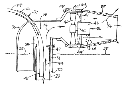
With further reference to Figures 2 and 3,
there will- be described the construction and
installation of the toilet bowl aspirating system of
the present invention. The aspirating system
comprises a blower support member 30 which has a
tubular adapter 31 for close sliding fit over the top
end 24 of the overflow tube 23. The tubular adapter
31 has a lower end 32 which extends below the top
water level 25 to provide a closed chamber 33 above
the top end of the overflow tube 23_ The blower
support member 30 has an exhaust end 34 which is also
positioned above the top water level 25 at a
predetermined distance therefrom whereby to receive
thereabout a filter element 35.,
As herein shown, a blower 36 is secured in the
exhaust end 34 and draws air from the top end of the
overflow tube and hence the plurality of ports 27 and
the air within th.e toilet bowl and this air flow is
indicated by arrows 37. Because the ports 27 are in
communication within the toilet bowl 11 when a person
is sitting on the toilet seat ,38, air from within the
toilet bowl will be aspirated through the overflow
tube by the blower 36 and filtered by the filter
element 35. and escapes from the area 38 above the top
water level 25 through the spaces about the cover 15
215I42~
~ _
-5-
and the top edge of the tank 14, which are never in
perfect sealing engagement. This filtered air escape
is indicated by arrow 37'.
It can also be seen that the blower support
member 30 isalso provided with a conduit 39 which has
an outer end portion 40 disposed above the member 30
and a lower end 41 which extends beyond the lower end
32 of the tubular adapter 31. . The member 30 has an
extension tube 30' which extends below the top water
level 25 and provides communication with the top end
of the tubular adapter 31 to permit evacuation of
water in the tank 14 when it rises above the level of
the top end of the adapter 31.
As better seen in Figure 1, before the blower
support member 30 is disposed over the top end 24 of
the overflow tube 23, the filler tube 26 was removed
and it is now repositioned in close fit within the top
end 40 of the conduit 39. Also, the tubular adapter
31 is provided with an abutment element, herein a
screw 42, at a predetermined location therein, and
projects inwardly within the tubular adapter 31 for_
seating abutment on the top end or top edge 24 of the
overflow tube 23. This provides for the exhaust end
34 to be positioned at a predetermined distance spaced
above the top water level 25 of the tank to ensure
that the filter element 35 is not in contact with the
water within the tank.
As herein shown, the filter element 35 is
constructed as a thick pouch of flexible material
impregnated with a carbon substance and has an open
end 43 which is dimensioned for close fit over a
collar 44' provided at the exhaust end 34. The.
flexible material of the filter has sufficient
rigidity to support itself spaced above the top water
level 25 and also provides protection and sound
absorption of the blower 36 which is mounted within
the collar 44'. The filter is easily interchangeable.
_2152427
6-
The tubular member 39 and the filler tube 24 are both
constructed of flexible plastic tubes. The reason
that the lower end 41 of the plastic tubular member 39
extends beyond the lower end 32 of the tubular adapter
3i is that it facilitates positioning this lower end
41 within the top end 24 of the overflow tube 23
during installation of the support member 30.
As shown in Figure 3, the blower 36 is
comprised of a DC motor 44 having a rotatable shaft 45
to which a fan 46 is secured. The, motor 44 is
supported within a support frame or housing 47 which
is glued or otherwise supported within the collar 44'
With additional references to Figures 4 to 7,
there will be described the manner in which the blower
36 is operated. As shown in Figure 4, a blower
activating switch 50 is secured over the top rim of
the tank 14 and positioned centrally over the front
wall 14' of the tank whereupon lifting of the toilet
seat 13 in the direction of arrow 51, and striking the
switch 50 will cause actuation_
As shown in Figure 5, the switch 50 is
comprised of a pair of flat contact blades 52 and 53,
electrically isolated from one another by a strip of
insulating matrial 49. The blades 52 and 53 are
shaped at an end 53' and 52' to define a U-shaped
clamp 54 whereby to hook the switch over the top edge
of the tank 14_ These U-shaped ends 53' and 52' of
the contact blades also constitute terminal ends to
which wires 55 are connected to respective terminals
of a battery as will be described later. The forward
contact blade 53 has a forwardly disposed section 56
provided with a rubber bumper 57 on which the seat
cover 13 will abut whereby to cause the contact end
portion 58 of the lblade 53 to contact the blade 52 and
cause a switch closure to actuate a timing circuit and
the blower 36.
X451427
As shown in Figure 6, the power supply is
provided by a 6 or 9 volt d.c. battery 60 which is
secured within a waterproof housing 61 also provided
with a clamp 62 to retain same within the upper
portion of the water tank 14 and inside thereof. The
housing 61 extends partly below the top water level 25
in the tank. If there is no space in the tank, then
the battery housing could be disposed outwardly at a
convenient location where it is not so apparent. A
cover 63 closes the waterproof houSing,6l.-_._At the
base of the housing 61, there is provided a circuit
block 64 under which or in which there is secured a
timer circuit 65_ Conductive strips 66 are provided.
on the top end of the circuit 64 to connect the wires
55 to the proper terminals 67 and 68 of the battery.
Wires 69 are connected to the blower motor 44.
The timer circuit 65 is illustrated in Figure 7
and maintains power to the motor 44 during a preset
time period, herein four minutes, after the closure of
the switch contact 50. After the expiration of the
timing cycle, power is automatically shut-off from the
blower motor 44 by the actuation of a relay 70.
Should it be desired to maintain the blower actuated
for a further cycle, or more cycles, all that is
necessary to do is for the user to apply pressure
against the seat cover 13 lying in front of the switch
50 whereby to cause a further switch closure and a
further actuation of the supply circuit during a
further four minute time cycle.,
It is within the ambit of the present invention
to cover any other obvious modifications, provided
such modifications are encompassed within the scope of
the appended claims.