Note: Descriptions are shown in the official language in which they were submitted.
WO94/13439 PCT/AU93100637
2~51~1~
"CUTTING APPARATUS"
This invention relates to cutting apparatus.
This invention has particular but not exclusive
application to cutting apparatus for use in opening sealed
5 containers such as envelopes, and for illustrative purposes
reference will be made to such application. However, it is
to be understood that this invention could be used in other
applications such as for making incisions in a material or
for shredding a material.
For safety reasons, it is undesirable to provide
disabled persons, epileptics or children in particular, or
persons traveling in a vehicle in general, with cutting
instruments having a cutting e,dge which during normal
conditions of use are accessible to parts of the human body
15 such as fingers or the like and which as a result of misuse
may injure the user such as when attempting to open sealed
envelopes or the like.
It is also noted that many couriers use envelopes or
bags made from a plastics material and wherein the bags are
20 difficult to open once the closure flap has been sealed even
with the aid of a pair of scissors. However, it is noted
that scissors tend to be rather bulky and typically include
sharp points and exposed cutting edges which may injure
persons or damage property if carried for example in a
25 persons pocket, handbag or brief case.
The present invention aims to alleviate one or more of
the above disadvantages and to provide cutting apparatus
which will be reliable and efficient in use.
With the foregoing in view, this invention in one aspect
30 resides broadly in
In one embodiment the cutting assembly may comprise a
fine wire which may be smooth or serrated.
In an alternative embodiment the cutting assembly may
include a cutting blade which may comprise one or more
35 cutting edges which may be sharpened or which may include a
WO94/13439 ~ 5 ~ PCT/AU93/00637
plurality of teeth. For example, the cutting blade may
include a single cutting edge which forms part of or is
integral with the incising end portion and wherein the
cutting blade may include an arcuate cutting edge or a
5 substantially straight cutting edge which may extend upwardly
from a lower end portion of the cutting blade whereby in use
a lower portion of the cutting edge may be employed to form
an incision in the material to be cut.
Alternatively the blade assembly may include a cutting
lO blade having a lower incising end portion which is
distinctive from a cutting edge extending upwardly therefrom.
For example, the incising portion may include a pointed end
portion, which may be sharp or, blunt, and wherein the cutting
edge may comprise a sharpened side edge of the cutting blade.
15 However it will be appreciated that the incising end portion
may be straight or curved.
In a preferred embodiment however, the cutting assembly
includes a cutting blade comprising a pair of opposing side
cutting edges separated at their distal end by a pointed
20 incising end portion having outwardly divergent cutting
edges.
In addition, the cutting assembly may be removable and
wherein the cutting assembly may also include locking means
for restricting access to and/or the removal of the cutting
25 assembly. For example worn or broken cutting blades may be
replaced by new or freshly sharpened blades, access to which
may be controlled by appropriate locking means.
In one embodiment the mounting means and the article
support means may be constituted by respective upper and
30 lower portions of the apparatus and wherein the position of
the upper portion relative to the lower portion may be fixed
or may be selectively varied. For example, the apparatus may
include mounting means and article support means maintained
in a fixed, spaced, relationship by connecting means.
Alternatively, the mounting means and the article
WO94tl3439 PCTIAU93/00637
2151Sl~
support means may be maintained in a spaced relationship by
connecting means which may be actuated so as to urge together
or otherwise reduce the spacing separating the mounting means
and the article support means.
In yet another embodiment, a portion of the mounting
means may be pivotally connected to a portion of the article
support means such that the opposing portions of the mounting
means on which the cutting assembly is mounted and the
article support means may be urged together and wherein the
lO mounting means may also constitute the actuation means.
For example, the cutting assembly may be mounted on a
mounting member which is pivotally connected to an article
supporting member and wherein ~the cutting assembly or cutting
blade mounted on the mounting member remote from the pivotal
15 connection may be urged toward the receiving portion of the
article supporting member by movement of the mounting member
in the general direction of the article supporting member.
The article support means or member may comprise a
substantially planar surface which is generally orthogonal to
20 a plane containing the cutting assembly and wherein the
receiving portion may include a recess and wherein the recess
and the incising end portion may be complementary.
Furthermore, the complementary recess may be arranged to
provide a shearing action against the cutting edges and/or
25 incising end portion of the cutting assembly and whereby in
use material to be cut may be placed between the article
support means and the mounting means, and a cutting operation
commenced by actuating the actuation means such that the
incising end portion is extended towards the receiving
30 portion so as to pierce the material. The cutting operation
may be continued by either repeating the operation thus far
described, or movement of the cutting assembly in a plane
containing the cutting portion whilst maintaining the cutting
assembly in its extended attitude.
In an alternative embodiment, the receiving portion may
WO94113439 2~ 12 PCT/AU93100637
be substantially flat and/or the receiving portion may be
constructed from a soft, resilient or moldable material.
The actuation means, in one embodiment, as referred to
above may comprise the mounting means pivotally connected to
5 the article support means. However, in an alternative
embodiment, the actuation means may comprise suitable means
for advancing the blade assembly such as a piston or plunger
extending upwardly from the blade assembly and which may also
be mounted on the mounting means.
The actuation means may also include biasing means such
as a spring whereby in use the blade assembly may be
maintained in an inoperative position unless actuated by the
actuation means.
The cutting apparatus may also be provided with guide
15 means adapted to at least partially conceal or prevent access
to the cutting assembly such as for example the cutting edge
and/or incising end portion of a cutting blade when retained
in an inoperative position by, for example, biassing means.
The guide means may alternatively, or in addition, provide
20 support for the cutting assembly at a position adjacent the
article support means whereby, for example, a relatively thin
cutting blade may be utilised.
The guide means may be mounted on the mounting means or
the article support means.
In the preferred embodiment, the mounting means, guide
means and article support means are hingedly connected
elongate members extending from a common hinged connection
and wherein the cutting assembly comprises a cutting blade
mounted on the mounting member such that the blade is
30 contained in a plane which is substantially parallel to the
axis of the aforementioned hinged connection. In addition,
the guide means, mounting means and article support means are
preferably spring biassed from a closed position wherein the
distal ends of the guide member, mounting member and article
35 support member are substantially abutting to an open position
WO94/13439 PCT/AU93/00637
~ 21 Sl 51 ,~
wherein the distal ends of the guide member, mounting member
and article support member are spaced apart.
In use, the mounting member and article support member
or at least the distal portions thereof are moved toward one
5 another with the guide member interposed therebetween to
cause the extension of the cutting blade from the guide
member and into operative engagement with the receiving
portion of the article support member.
In a further preferred form, the guide member is
lO interposed between the article support member and the
mounting member and includes abutment means interposed
between the guide member and the article support member
whereby the receiving portion is spaced from the guide member
a desired distance so that a desired length of cutting blade
15 is exposed as the cutting portion.
The cutting apparatus may further include a safety lock
to prevent the article support member being opened away from
the rem~;n~er of the cutting apparatus whereby the cutting
portion may be exposed.
In order that this invention may be more readily
understood and put into practical effect, reference will now
be made to the accompanying drawings which illustrate a
preferred embodiment of this invention and wherein:-
FIG. 1 is a side view of cutting apparatus constructed
in accordance with the present invention with the
cutting assembly shown in its extended or operative
position;
FIG. 2 is a side view of cutting apparatus illustrated
in figure l but wherein the cutting assembly is shown in
its retracted or inoperative position;
FIG. 3 is a plan view of the cutting apparatus
illustrated in figure 1;
FIG. 4 is a cross-sectional side view of an article
support member belonging to the cutting apparatus
illustrated in figure 1;
WO94/13439 PCTIAU93/00637
~ ~ 5 2
FIG. 5 is a cross-sectional side view of the cutting
apparatus illustrated in f igure 1;
FIG. 6 is a cross-sectional side view of the cutting
apparatus illustrated in figure l with the cutting
assembly shown in its operative position but wherein the
locking means has been removed, and
FIG 7 is a front view of a cutting blade belonging to
the cutting apparatus illustrated in figure 1.
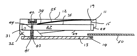
Figures 1 to 6 illustrate a cutting apparatus lO
lO comprising a cutting assembly 11 mounted on mounting
means/actuation means 12 which is pivotally connected to
article support means 13 having a receiving portion 14.
The cutting assembly 11 includes a cutting blade 15
having an incising end portion 16, comprising two
15 substantially straight cutting edges 17 diverging outwardly
from a centrally located pointed end, and a pair of opposing,
straight, cutting edges 18 extending upwardly therefrom as
generally illustrated in figure 7. The base of the cutting
blade 15 is mounted on the mounting means or mounting member
20 12 generally at 19.
The mounting means or mounting member 12 is rather
elongate and includes a housing comprising opposing side
walls 20 separated by a top wall 21 and a front wall 22. The
housing also includes a cylindrically shaped recess 23 formed
25 in the top wall 22 and wherein the recess includes a
centrally located bore 24 formed in the base wall thereof.
The housing is used to house biasing means comprising a leaf
spring 25, one end of which is attached to the underside of
the top wall 21, and guide means comprising an elongate guide
30 member 26 adapted to at least partially conceal the cutting
assembly 11 in it's inoperative position, as illustrated in
figures 2 and 5, and to provide support for the cutting edges
18 when the cutting assembly is in it's operative position,
as illustrated in f igures 1 and 6.
The guide member 26 comprises a pair of opposing side
WO94/13439 PCT/AU93/00637
~,,S~
walls 27 separated by a front wall 28 and a base wall 29,
which includes a transversely orientated slit 30 formed
therein adjacent said front wall through which the cutting
blade 15 may selectively extend.
The opposing or fixed end 31 of the guide member 26 is
pivotally connected to the mounting member 12 and to opposing
mounting brackets 32, of the article support means or member
13, by a pin 33 which extends through aligned apertures
formed therein.
The free end 34 of the leaf spring 25 rests upon or
abuts against the upper edges 35 of the side walls 27 of the
guide member 26 as illustrated in figures 5 and 6.
The base wall 29, of the guide member 26, is maintained
in a spaced relationship relative to the planar base 36, of
15 the article support member 13, by an upstanding tubular
abutment 37 located therebetween. The abutment 37 is mounted
on the base 36 such that the bore 38 is aligned with a
similar bore 39 formed in said base and which communicates
with a cylindrically shaped recess 40 formed therein.
The free ends of the mounting member 12, the guide
member 26 and the article support member 13 are prevented
from being splayed apart by locking means comprising a
resilient locking member 41 having a head portion 42
slideably located within the recess 23; a tail portion 43
25 fixed within the recess 40; and a stem 44 connecting the head
portion 42 and the tail portion 43, said stem extending
through bores 38 and 39 and an aligned aperture formed in the
base wall 29 of the guide member 26.
In use, the cutting apparatus may be held in the palm of
30 a user's hand and wherein an article 50 to be cut, such as
the portion of an envelope adjacent an edge thereof, may be
supported between the article supporting member 13 and the
guide member 26 by the user's other hand in a fashion as
generally illustrated by figures 3, 5 and 6.
The user may, by tightening his or her grip about the
WO94/13439 PCTIAU93/00~7
2~1512 ~
apparatus lO overcome the resistance provided by the leaf
spring 25 and thereby urge the free ends of the mounting
member 12 and the article support member 13 together such
that the incising end portion 16 extended through the slit 30
5 engages the complementary shaped recess 14 so as to form an
incision in the article 50.
The user may, whilst maintaining sufficient pressure on
the mounting member/actuating member 12, draw or slide the
apparatus lO relative to the material in a general direction
lO indicated by arrow 51, for example, such that the cutting
edge 18 cuts the portion of the material 50 which it bears
against. It will however be appreciated that the cutting
edges 18 may be slid in either, straight lines or curves or
intersecting lines or curves to cut the material as desired
15 with a slicing action. Furthermore, the cutting edges 18 of
the cutting blade 15 may be arranged at right angles to the
intended direction of the slicing action, but may also be
arranged at a non-perpendicular angle as appropriate.
It will also be appreciated that the portion of the
20 guide member 26 surrounding the slit 30 provides support for
the thin cutting blade during use, ie. prohibits undue
relative movement of the cutting blade, should the blade
encounter any resistance.
Once the pressure on the mounting member 12 is released,
25 the action of the spring 25 returns the cutting assembly 11
to its former inoperative position shielded within the
confines of the housing and the guide member 26, as shown in
figures 2 and 5.
It will be appreciated that during use the abutment 38
30 maintains a minimum spacing between the guide member 26 and
the base 36 of the article supporting member 13.
Whilst not limiting the use of this invention to a
particular use or application, it is believed that the
cutting apparatus described herein may be suitable for use by
35 disabled persons, children or persons having only one upper
WO94/13439 ~ PCT/AU93/00637
' 1SlSl~ .
limb and that the configuration of the shielded cutting
assembly 11 is unlikely to injure users of the apparatus.
It will of course be realised that while the above has
been given by way of illustrative example of this invention,
5 all such and other modifications and variations thereto as
would be apparent to persons skilled in the art are deemed to
fall within the broad scope and ambit of this invention as is
defined in the appended claims.