Note: Descriptions are shown in the official language in which they were submitted.
PCTJGB93102536
WO94/13398 2 IS 13~ 1
1 "A Process Vessel"
3 This invention relates to a contacting column
4 redistributor for use in effecting improved fluid
distribution through a process vessel.
7 Columns with dumped or random packings, stacked
8 packing~ or structured packings are widely used in the
9 chemical, oil, gas and other process industries for
separation processes (for example, absorption,
11 desorption, rectification, stripping and distillation)
12 and as reactors in which packings are used to bring
13 gases and liquid into direct contact in order to
14 transfer heat or constituents from one phase to the
other. Two of the great advantages of packed columns
16 are the low capital cost and the large contact area of
17 packings.
18
19 Liquid and gas channelling and the difficulty of adding
or removing heat are the main shortcomings of packed
21 columns.
22
23 Packed columns suffer from liquid and gas channelling
24 even when they are vertically positioned, and this
channelling can cause a reduction in column efficiency,
WO94/13398 ~S I 8 '~ '3 PCT/GB93/0253
1 while packed columns which are used on board floating
2 platforms and processing ships may suffer a much more
3 serious liquid and gas channelling due to tilt and
4 motion caused by marine waves. Channelling could cause
a severe reduction of performance even under tilt of a
6 few degrees.
8 The channelling type and severity could depend on
9 whether the columns are used onshore or offshore, as
will be explained as follows:-
11
12 Onshore Applications
13
14 The main short comings of the vertically positioned
packed column (VPPC) is the non uniform distribution of
16 the liquid and gas phase over the whole cross-sectional
17 area of the column due to voidage variation near the
18 wall area. The wall area width is equal to one packing
19 diameter, (Gunn, D J 1980 Chem Eng Sci 35 2405).
21 The voidage near the wall is higher than that at the
22 rest of the cross sectional area of the packed column.
23 This voidage variation will lead to the channelling of
24 liquid and gas phases through the wall area. More
serious channelling could take place if the li~uid
26 distributor, located at the top of the column, was
27 tilted, partially blocked or poorly designed or
28 constructed.
29
It has been reported by Baker S A lg80 M Sc thesis,
31 University of Wales and by Baker S A 1987, Ph D thesis,
32 University of Wales that packed columns may suffer from
33 li~uid and gas channelling even with the supposedly
34 good design criteria i.e. with high ratio of column
diameter to packings diameter. This finding was valid
WO94/13398 21518 2 3 PCT/GB93102536
1 for co-current and counter-current operations.
2 Many workers, among them Morris G A and Jackson J 1953,
3 Absorption Towers, London: Butterworths Scientific
4 publications and Mullin J W 1957, Industr Chem Mfr 33
408 have shown that liquid and gas maldistribution can
6 effect the efficiency and performance of the packed
7 column and reduce the number of mass transfer stages in
8 a given depth of p~c~;ng. The magnitude of this
g reduction varies with the degree of maldistribution
being studied. It has been reported that very long,
11 onshore used, packed columns which tilted under the
12 effect of high wind, or their own weight or from
13 thermal effects or which tilted when their foundation
14 settled, suffered additional performance reduction
similar to the performance reduction suffered by tilted
16 packed columns used offshore on board floating
17 production platforms and ships.
18
19 Offshore Applications
21 There are increasing demands for floating oil
22 production platforms; as well as being cheaper than
23 fixed production platforms, they can be relatively
24 easily relocated after the depletion of the oil of the
field. Also there are increasing demands for offshore
26 chemical plants mounted on board ships, as they become
27 more favourable than onshore chemical plants for
28 certain duties due to rising expenses in construction
29 of waste disposal and pollution control plants.
31 Floating platforms and processing ships permit some
32 horizontal and vertical motion and tilt. This motion
- 33 and tilt can cause severe li~uid and gas channelling,
34 which could lead to a severe reduction in the
performance of the packed columns. The main cause of
W094/133g8 2 ~5~S~3 PCT/GB93/02~'
1 the reduction in the performance of the tilted packed
2 columns is due to the severe liquid and gas
3 channelling, where liquid tends to channel through one
4 side of the column and the gas channels through the
other side of the column, hence reducing the total
6 surface area of contact between the liquid phase and
7 the gas phase, and reducing the degree of contact
~ between the two ph~cec in the column whether the
9 ~o~ess is distillation, absorption, desorption,
stripping, or chemical reaction.
11
12 A permanent inclination is considered to be the most
13 critical situation for a separation column. Some
14 authors have described the efficiency drop of packed
columns in inclined positions.
16
17 For a distillation column Weedman J A and Dodge B F
18 1947, Ind and Engng Chem 39 732 have shown that,
19 beginning at about 1inclination, efficiency
drastically drops to about 50% at 2.5.
21
22 At present there are fluid redistributors designed to
23 correct channelling in process vessels at discrete
24 positions along the length of the vessel. However
these redistributors are designed such that the fluid
26 is redistributed on specific planes of the packed
27 column which creates a sizeable bottleneck in higher
28 flow rates of the fluid and can occupy a significant
29 volume of the column and increase column weight.
31 In a tilted or moving column, these fluid
32 redistributors may increase the li~uid and gas
33 channelling and accelerate its occurrence due to their
34 design which help transfer the liquid quickly to the
lower inclined part of the column from the other part
WO94/13398 2 1 SI B23 PCT/GB93/02536
- i
1 of the column of the same axial level.
3 According to the present invention there is provided a
4 process vessel for achieving contact between at least
one fluid passing through the vessel and a packing
6 material contained therein, the process vessel
7 comprising a peripheral wall disposed around a
8 longitll~; nA 1 axis and having an inlet for permitting
9 entry of fluid into the vessel and an outlet for
permitting exit of fluid from the vessel, the vessel
11 including a redistributor which follows a locus which
12 is not perpendicular or parallel to the longitudinal
13 axis.
14
The process vessel may be an upright cylinder, square
16 or rectangular prism or any other suitable shape;
17 alternatively its cross-sectional area may vary along
18 its height, for example in the form of a frusto-cone.
19
Typically, other inlet and outlet configurations of the
21 processing vessel are possible. For example one outlet
22 at one end and one inlet and one outlet at the other
23 end or one inlet at one end and one outlet at the other
24 end to permit two or more fluids to be passed through
the vessel in either the same direction or different
26 directions. Alternatively, one or more of the inlets
27 and/or outlets may be located away from the ends.
28
29 Typically, said process vessel is a contacting column
30 for use in achieving mutual contact between a first and
31 a second fluid flowing therethrough and the packing
32 material contained therein or between the fluid and the
33 packing material.
34
The redistributor may be in the form of a single
WO94113398 ~ 23 PCT/GB93/025~'
1 element or the form of a discontinuous element
2 comprising a num~er of sections.
4 Preferably, the element extends around the vertical
axis within the process vessel and generally follows
6 the internal contours-of the peripheral wall of said
7 vessel.
g In some structures two or more elements may be used.
11 Typically, on any plane drawn at right angles to the
12 longitudinal axis the element or elements do not occupy
13 more than a small proportion, typically less than 20%,
14 for example less than 10~, preferably less than 5~,
most preferably less than 1%, of the total cross
16 sectional area of the process vessel as measured on
17 that plane. One of the benefits of this is the
18 reduction in the potential for flooding of the vessel
19 in some operating conditions.
21 The element is continuous at least for some minimum
22 length. For vessels which are symmetrical about the
23 longitll~;n~l axis, such as right cylindrical and
24 frusto-conical vessels, the element may extend along a
generally helical path. The number of turns of the
26 helical element per unit height of vessel can be
27 selected over a wide range and may vary over the total
28 height of a vessel. The generally helical path may be
29 either clockwise or anti-clockwise in direction of
rotation or both. For a di~continuous element, the
31 different sections may have different directions of
32 rotation.
33
34 Preferably, the element has one edge connected to the
internal sur~ace of the peripheral wall and another
WO94/13398 S1~823 PCT/GB93/02~36
. ~
1 edge spaced from the axis. The former edge of the
2 element should be sufficiently close to the internal
3 surface of the peripheral wall to avoid substantial
4 flow of a second fluid up the wall. The element may be
.
mounted by any convenient means e.g. by means of
6 welding, gluing, screws, brackets or jamming. One
7 means of jamming a helical element is to partially
8 rotate one end relative to the other in order to reduce
9 the external overall diameter of the helix. Once the
element is placed inside the column it is then allowed
11 to expand towards its natural larger diameter by which
12 expansion it becomes jammed inside the column. Removal
13 from the column may be accompanied by reversing this
14 procedure. The element can also be made as an integral
part of the peripheral wall or mounted on a support
16 rail.
17
18 Preferably the element or elements are distributed
l9 around the entire circumference of the vessel such that
there is no clear through line down the inner surface
21 wall of the vessel, when viewed along the longitll~; n~
22 axis.
23
24 Alternatively, the element may be connected to
structured packings of a packed process vessel. This
26 is to improve the sealing of the structured packing to
27 the inside wall of the column and to i~ove
28 distribution of fluids in a vertical or tilted column.
29
30 Tne element may be provided witn holes o~ a suitable
31 number and size and shape, for example, to provide some
32 flow of a first fluid to the peripheral wall region
33 directly below the element while allowing part of a
34 second fluid to flow through the holes. For an elemer~
fitted with holes, the size and spacing of the holes
WO94113398 21518 23 PCT/GB93102~3~
1 may differ at different positions in the vessel as, for
2 example, near the top and base of said vessel.
4 The element may be plane, corrugated, tubular, V or
other convenient section, and may be at right angles to
6 or oblique to the peripheral wall.
8 Preferably, the element has one or more baffles fixed
9 to a lower face of the element for directing a second
fluid from the peripheral wall region to a central
11 region and to skim off any liquid which may flow on or
12 below the lower face of the element.
13
14 The element may have extended vanes of equal or varying
lengths projecting radially inwardly towards the
16 central region for help in directing a first fluid
17 further away from the peripheral wall region towards
18 the central region.
19
In certain examples of the invention, the element may
21 have a weir on an upper face or on an outer edge to
22 enhance redistribution of a first fluid when flowing at
23 a higher rate. The top edge of the weir, if fitted,
24 may be notched or serrated.
26 Preferably, the element is suitable for co-current and
27 counter-~Lellt operations and for vessels in which one
28 fluid flows through a bed of solid particles. In a co-
29 current operation, a first and second fluid flow in the
sa~e direction whereas in a counter-current operation a
31 first and second fluid flow in generally opposite
32 directions.
33
34 Typically, the invention is suitable for all types of
packings, such as random, dumped, stacked or structured
- 21~1823
WO94/13398 PCT/GB93/02536
1 packings. Such packings may be used for operations
2 such as distillation, stripping, absorption,
- 3 adsorption, liquid extraction or chemical reactions.
The element may be solid in cross-section or hollow. A
6 hollow or solid element may have a square, rectangular,
7 circular or other convenient cross-section. An element
8 of hollow cross-section may also be utilised to add or
9 remove heat from the fluid or fluids by providing an
internal flow of heating or cooling medium as
11 appropriate. Alternatively, heat transfer surfaces
12 could be introduced directly above or below the element
13 to heat or cool fluid which flows preferentially on or
14 near the element.
16 The lower end of an element nearest the base of the
17 process vessel may be fitted with a transverse weir or
18 other arrangement to impede flow of liquid off that end
19 and thus improve liquid distribution below the element.
21 At the top of a vessel the element may be designed to
22 help the initial liquid distribution e.g. by extending
23 the element under the feed zone and having a higher
24 number of holes per unit area in that zone.
26 Another advantage of the present invention in some
27 applications is reduction in pressure drop over the
28 packed vessel by permitting the use of larger packings
29 without the usual disadvantage of greater wall
channel~ing of liquid and/or gas.
31
: 32 Foaming can occur in some packed vessels and adversely
33 affect performance. T~e present vessel may enable the
34 gas to sweep part of the foam onto the element where it
Will have more opportunity to collapse.
WO94/13398 2 1 51 ~ 2 3 PCT/GB93/0253~
l Typically, the fluid or fluids flowing through the
2 process vessel comprise a liquid or a gas or
3 combination thereof. Typically, the first and second
4 fluids may be respectively a liquid and a gas.
6 Embodiments of the invention will now be described, by
7 way of example, with reference to the accomp~nying
8 drawings in which:-
Fig. lA is an isometric view of a first embodiment
11 of a process vessel and redistributor in
12 accordance with the present invention;
13 Fig. lB is a top plan view of Fig. lA;
14 Fig. lC is a sectional view of Fig. lA;
Fig. 2A is an isometric view of a portion of a
16 first embodiment of the redistributor;
17 Fig. 2B is a side view of Fig. 2A;
18 Fig. 2C is a side view of Fig. 2A provided with a
19 self-locking supporting rail;
Fig. 3A is an isometric view of a portion of a
21 second embodiment of the redistributor;
22 Fig. 3B is a side view of Fig. 3A;
23 Fig. 4A is an isometric view of a portion of a
24 third embodiment of the redistributor provided
with baffles;
26 Fig. 4B is a side view of Fig 4A;
27 Fig. 5A is an isometric view of a portion of a
28 fourth emhoAiment of the redistributor provided
29 with a weir;
Fig. 5B is a side view of Fig. 5A;
31 Fig. 6A is an isometric view of a portion of a
32 fifth embodiment of the redistributor;
33 Fig. 6B is a side view of Fig. 6A;
34 Fig. 7 is a plan view of a portion of a sixth
embodiment of the redistributor provided with
W094/13398 11 PCT/GB93/02536
1 holes;
2 Fig. 8A is an isometric view of two portions of
3 the redistributor of Fig. 6A connected by a plane
4 at right angles to the two sections;
Fig. 8B is an isometric view of two portions of
6 the redistributor of Fig. 6A not connected;
7 Fig. 9 is a partial breakaway view of a second
8 embodiment of the process vessel and redistributor
9 provided with structured packings;
Fig. lOA is an isometric view of a third
ll embodiment of the process vessel and
12 redistributor;
13 Fig. lOB is a plan view of Fig. lOA;
14 Fig. 11 is a sectional view of a fourth embodiment
of the process vessel and redistributor; and
16 Fig. 12 is a sectional view of the fifth
17 embodiment of the process vessel and
18 redistributor; and
19 Fig. 13 is an isometric view of a portion of a
seventh embodiment of the redistributor.
21
22 For the sake of clarity packings are not shown in Figs.
23 1 to 8, and 10 to 12.
24
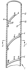
Referring to Figs. lA to lC which show a first
26 embodiment of a process vessel and redistributor 1, the
27 process vessel and redistributor 1 comprises a process
28 vessel 2 in the form of a cylindrical column and a
29 redistributor 4 which follows a generally helical locus
3. The redistributor 4 is connected by a supporting
31 rail 6 to an inside face 10 of a column wall 8. The
32 symbol " " represents the angle between the helical
33 wall redistributor 4 and a horizontal.
34
The length of the helical wall redistributor 4 is the
WO94/13398 2151 8 ~ 3 PCT/GB93/0253~
` 12
1 helical distance between point A and B" passing through
2 the points B, C, D, A', B', C', D', and A". The length
3 depends on the inside diameter of the column 2 and the
4 number of loops used and the angle between the plane of
the helical wall redistributor 4 and the horizontal
6 " ".
8 In Figs. lC, 2A and 6A, ZZ' defines a plane at right
g angles to the longitudinal axis. It can be seen from
Fig. lC that the proportion of cross-sectional area of
11 the process vessel obstructed by the redistributor 4 in
12 that plane is small.
13
14 Figs. 2A to 2C represent, in greater detail, a first
embodiment of a short portion of the helical wall
16 redistributor 4. The helical wall redistributor 4
17 comprises a helical plate 12 having an upper face 14
18 and a lower face 16. The plate 12 has a width w and a
19 thickness t. An angle, 0, between the plane of the
upper face 14 of the helical wall redistributor 4 and
21 the plane of the column wall 10 is equal to 90. The
22 helical wall redistributor is supported by the
23 supporting rail 6B (as shown in Fig. 2B) to the inside
24 face 8 of the column wall 10. This may be by gluing,
welding or other means. In Fig. 2C the supporting rail
26 6C has a self locking design.
27
28 The plane ZZ' at right angles to the horizontal axis as
29 shown in Fig. 2A shows the small proportion of cross-
sectional area of the process vessel obstructed by the
31 redistributor 4 in that plane.
32
33 Referring to a second embodiment of the helical wall
34 redistributor 4 as shown in Figs. 3A and 3B, the
helical wall redistributor 4 is similar to that shown
W094/13398 21 Sl 823 PCTIGB93102536
1 in Figs. 2A to 2C with part of the upper face 24 and
2 the lower face 26 of the helical plate 22 at an oblique
3 angle. The angle 0 between part of the plane of the
4 upper face 24 of the helical wall redistributor 4 and
the plane of the column wall 10 is a value other than
6 90 resulting in the obli~ue angle of the helical plate
7 22.
9 In Figs. 4A and 4B which show a third embodiment of a
portion of the helical wall redistributor 4, baffles 30
11 are fixed to the lower face 16 of the helical plate 12.
12 The baffles 30 may be fixed to the lower face 16 of the
13 helical plate 12 by welding, gluing or other means.
14
A fourth embodiment of the helical wall redistributor 4
16 shown in Figs. SA and 5B. This is similar to that of
17 Figs. 4A and 4B but also includes a liquid weir 40
18 fixed to the uppe~ face 14 of the helical plate 12.
19 The liquid weir 40 is located on the upper face 14 and
at an outer edge of the upper face 14 opposite to the
21 edge fixed to the inside face 8 of the column wall 10.
22
23 In Figs. 6A, 6B which show a fifth embodiment of the
24 helical wall redistributor 4, the helical plate 50 is
made of flat plate only and is fixed to the column wall
26 10 by means of a weld 52 on an inside edge 54 of the
27 plate 50 fixed to the column wall 10.
28
29 In Fig. 8A two portions of redistributor 4 are shown
with a second portion 56 at a lower level t~an a f irst
31 portion 50, 56 being connected by a plate 58. In Fig.
32 8B the first and second portions 50, 56 are not so
33 connected allowing for the helical wall redistributor 4
34 to be discontinuous.
W094/13398 PCT/GB93/Ot53~
21S1823 14
1 In use the helical wall redistributor 4 is fixed to the
2 column wall 10 by means of the supporting rail 6 or by
3 directly welding the helical plate 50 to the column
4 wall as shown in Figs. 6A, 6B, 8A and 8B or by any
other suitable means. When using the supporting rail 6
6 the helical wall redistributor 4 is chosen and slid on
7 to the supporting rail 6 after the removal of a
8 previous helical wall redistributor 4. The helical
9 wall redistributor 4 may be made of shorter pieces slid
one next to the other on the supporting rail 6 until
11 the required length is achieved.
12
13 The material of construction of the helical wall
14 redistributor 4 and that of the supporting rail 6 may
be chosen to suit the specific use, and it may be made
16 from ferrous or non-ferrous metals, polymers or any
17 other suitable material.
18
19 In use, the column 2 including any redistributor as
shown in Figs. 1 to 8 is packed (not shown) and a first
21 fluid such as a liquid is introduced at one end of the
22 column 2 with a second fluid such as a gas introduced
23 at the other end of the column 2. The process involves
24 the contact of the liquid and the gas in the packed
column 2 to transfer heat or constituents from one
26 phase to another. To prevent liquid and gas
27 channelling in the packed column 2 and to provide an
28 efficient operation and performance of the process the
29 helical wall redistributor 4 is introduced into the
column to provide effective liquid and gas
31 distribution.
32
33 If the column 2 shown in Figs. lA to lC, packed as
34 described above, is considered to be inclined to the
left to represent the effect of tilt and motion which
WO94/13398 1 Sl 823 PCT/GB93/02536
_ 15
1 is caused by marine waves or other effects, the
2 following characteristics and advantages of the wall
3 redistributor may be found. The upper face 14 or 24 of
4 the helical wall redistributor 4 wipes the liquid from
the column wall 10 and from its adjacent area, with an
6 area of high liquid influx (AHLI) around the areas B,
7 B' and B" as shown in Figs. lA and lC. Part of the
8 wiped liquid is redirected by the upper face 14 or 24
9 of the helical wall redistributor 4 to the other side
of the column 2 at a lower axial level and an area of
11 low liquid influx (ALLI) such as the areas around D, D'
12 and other parts of the packed column 2 which results in
13 an improved liquid irrigation in these areas.
14
For the inclined column 2 the helical wall
16 redistributor 4 creates a higher resistance to the
17 liquid flow through the column wall area 10 and through
18 the AHLI around the points B, B' and B" forcing part of
19 the liquid away from these areas towards the central
axis thus reducing the extent of column cross-sectional
21 area which would otherwise suffer from low liquid flux.
22
23 This results in an improved liquid and gas distribution
24 at the lower axial level of the packed column 2.
26 The lower face 16 or 26 of the helical wall
27 redistributor 4 creates a resistance to gas phase flow
28 and forces it to change direction from the column wall
29 area 10 and its ad~acent ALLI and directs it towards
the AH~I, leading to an ; ~vved contact between the
31 gas and liquid phase.
32
33 In Figs. 4A, 4B, 5A and 5B the presence of the baffles
34 30 enhance the effect of changing the direction of the
gas phase flow and forcing it to change direction. The
W094/13398 ; ; PCT/GB93/0~3~
21~1823 16
1 redistribution of the gas stream reduces the variation
2 in velocity of the gas phase flow over a
3 cross-sectional area of the packed column 2 which in
4 turn leads to improved performance of the packed column
2.
7 In ~he case where the packed column 2 is in a vertical
8 position the helical wall redistributor 4 wipes the
9 channelled liquid of the column wall area 10 and
directs it back to a main section of the packed column
11 2 reducing the liquid channelling in the column wall
12 area 10. In addition, the helical wall redistributor 4
13 creates more turbulent gas flow in the packed column 2
14 which leads to a more even gas composition over a
cross-section.
16
17 In Figs. 5A and 5B the presence of the liquid weir 40
18 could enhance liquid redistribution to the other side
19 of the packed column 2, for example, when the column is
tilted.
21
22 The upper face 14 or 24 of the helical wall
23 redistributor 4 may be corrugated to direct part of the
24 wiped liquid towards the central region of the packed
column 2, at the same axial level, and allowing the
26 rest of the liquid to flow to the other side of the
27 packed column 2 at a lower axial level.
28
29 The helical wall redistributor 4 may have extended
vanes of equal or different lengths helping to direct
31 part of the wiped liquid and the gas further away from
32 the column wall area 10. The vanes may project
33 inwardly toward the centre of the packed column 2 at a
34 lower level.
W094/13398 21 5 I 8 2 3 PCT/GB93/02536
1 Fig. 7 shows a sixth embodiment of the helical wall
2 redistributor 4. A helical plate 60 includes holes 62.
3 The presence of the holes 62 allows some liquid flow to
4 the column area directly below the helical wall
redistributor 4 and may let part of the gas in that
6 area to flow through the helical wall redistributor 4
7 which results in a further improvement in the
8 performance of the packed column 2.
The improvement in the performance of the packed column
11 2 is outlined in the table of results (see below).
12
13 The diameter of the column 2 is approximately 40 cm
14 with the width of the helical wall redistributors 4
being approximately 8 cm and the angle is in the region
16 of 30. A helical plate 60 includes holes 62 of
17 approximately 7 mm in diameter. The size of the holes
18 62 may vary with holes 62 having alternate diameters
19 such as 7 mm and 9.5 mm.
21 The following symbols referred to in the table of
22 results are:
23
24 NTU - Number of transfer units (measure of
performance)
26
27 GS - No helical wall redistributor 4 was used
28
29 GSW - helical wall redistributor 4 was used but it
3 0 was not provided with holes
31
32 GSWH - helical wall redistributor 4 with holes, each
33 hole being 7 mm in diameter
34
(GS)o - Value of NTU for GS in a vertical position
W094/13398 2 i S ~ 8 ~ 3 PCT/GB93/0253~
1 (GS)i - Value of NTU for GS at a particular angle of
2 tilt
3 GSWi - Value of NTU for GSW at a particular angle of
4 tilt.
6 GSWHi - Value of NTU for GSWH at a particular angle of
7 tilt
9 %VE - NTU angle X 100
----------_______ ___
11 NTU vertical
12
13 ANG - Angle of tilt of column, degrees
14
15 L, G - Flow rate of liquid and gas, litres/minute
16
17 GS GSWH GSWHi GSWHi GSWHi
18 % % %
19 ANG L G NTU %VE NTU %VE (GS)o (GS)i GSWi
20 0.0 67.0 42.0 3.636 100.0 6.51 100.0 178.9178.9 125.
21 3.0 67.0 42.0 2.885 79.4 5.59 85.9 153.7193.7 114.2
22 5.0 67.0 42.0 2.615 71.9 4.99 76.7 137.190. *
23 8.0 67.0 42.0 2.497 68.7 4.44 68.3 122.2178. 112.4
24
SUB~i 111 ~JTE SH~Er
WO94/13398 21~1 8 23 PCTIGB93/02536
19
1 GS GSWH GSWHi GSWHi GSWHi
2 % % %
3 ANG L G NTU %VE NTU %VE (GS)o (GS)i GSWi
5 0.0 67.0 84.0 4.106 100.0 7.73 100.0 188.3 188.3 137.
6 3.0 67.0 84.0 3.460 84.3 6.60 85.4 160.8 190.8 120.3
7 5.0 67.0 84.0 3.024 73.6 5.65 73.1 137.7 187.0 *
8 8.0 67.0 84.0 2.916 71.0 5.07 65.6123.5 174. 128.3
10 0.0 67.0 168. 4.185 100.0 8.10100.0 193.4 193.4 14~.9
11 3.0 67.0 168. 3.884 92.8 6.9886.2 166.6 179.6 121.1
12 5.0 67.0 168. 3.450 82.4 5.8972.8 140.8 170.8 *
13 8.0 67.0 168. 3.173 75.8 5.6769.4 134.3 177.1 114.2
14
15 0.0 67.0 353. 4.449 100.0 8.02100.0 180.4 180.4 140.4
16 3.0 67.0 353. 4.147 93.2 7.7196.0 173.3 185.8 125.5
17 5.0 67.0 353. 3.730 83.8 6.2277.6 139.9 166.9 *
18 8.0 67.0 353. 3.494 78.5 5.7770.7 127.4 162.2 110.6
19
20 0.0 168. 42.0 2.823 100.0 3.62100.0 128.1 128.1 122.4
21 3.0 168. 42.0 2.111 74.8 3.1988.4 113.2 151.4 116.1
22 5.0 168. 42.0 1.896 67.2 2.8879.6 102.0 151.8 *
23 8.0 168. 42.0 1.729 61.2 2.4567.9 86.9141.9 100.0
24
25 0.0 168. 84.0 3.258 100.0 4.53100.0 138.9 138.9 115.1
26 3.0 168. 84.0 2.786 85.5 4.1792.2 128.1 149.8 116.1
27 5.0 168. 84.0 2.563 78.7 3.8585.0 118.1 150.0 *
28 8.0 168. 84.0 2.249 69.0 3.3874.8 103.8 150.4 102.0
29
30 0.0 168. 168. 3.452 100.0 4.87100.0 141.1 141.1 109.2
31 3.0 168. 168. 3.311 95.9 4.6294.9 133.5 139.5 110.8
32 5.0 168. 168. 3.043 88.1 4.5693.7 133.2 150. *
33 8.0 168. 168. 2.673 77.4 4.0683.4 117.6 151.9 103.5
34
SUB~ 1 I UTE SHEET
W094/13398~ PCTIGB93fO253
1 GSGSWH GSWHi GSWHi GSWHi
2 % % %
3 ANG LG NTU %VE NTU ~VE (GS)o (GS)i ~SWi
4 0.0 168. 353. 3.844 100.0 5.01 100.0 130.3 130.3 107.7
5 3.0 168. 353. 3.506 91.~ 4.83 g6.4 125.7 137.8 1~4.8
6 5.0 168. 353. 3.453 89.8 4.82 96.3 125.4 141.5 *
7 8.0 168. 353. 3.022 78.6 4.46 89.1 116.3 147.7 105.4
8 * No experiment carried out for these combinations of
9 conditions.
11 As can be seen from the table of results the measure of
12 performance is further improved when using a helical
13 wall redistributor 4 with holes 62 and illustrates the
14 advantages of holes for some conditions of operation.
16 In Fig. 9 which represents a second embodiment of the
17 process vessel and redistributor 70, the helical
18 redistributor 4 is fixed to structured packings 72
19 which result in the formation of a continuous helix
when segments of the structured packings 72 are stacked
21 together.
22
23 The structured packing 72 may include the helical
24 redistributor 4 in the outermost area of the structured
packings 72 having one or more layers of the helical
26 redistributor 4.
27
28 For the structured packing 72, the helical wall
29 redistributor 4 may be made of a suitable flexible or
soft material which may be fixed to the column wall 10
31 and at the same time make tight contact to the packings
32 72 themselves.
33
34 A third embodiment of a process vessel and
redistributor 80 is shown in Figs. lOA, lOB with the
SUB~ 111 ~JTE SHE~T
WO94/13398 PCT/GB93/02536
21518~3 21
1 process vessel 82 being in the form of a cuboidal
2 column with a wall redistributor 4 which follows a
3 square helical locus 83 (see Fig. lOA). The
4 redistributor 4 is fixed onto the column walls 10 as in
Figs. lA to lC. The length of the wall redistributor 4
6 is the distance between the points AR and AR passing
7 through the points BR, CR and DR.
9 Fig. 11 shows a fourth embodiment of a process vessel
and redistributor 90, the process vessel 92 being in
11 the form of a cylindrical column. The peripheral wall
12 of the process vessel 92 comprises three separate
13 layers; an outermost layer 94, a middle layer 96 and
14 an inner layer 98. In this particular example, the
outermost layer 94 is made from steel and the middle
16 layer 96 and inner layer 98 are both made from brick.
17
18 As shown in Fig. 11 the redistributor consists of a
19 number of discrete elements 100. Each element 100 lies
on a locus 93, which is generally helical. Each of the
21 elements 100 is integral with or fixed to the inner
22 layer 98 along a generally descending helical locus 93.
23
24 Each element 100 of the redistributor has a top surface
which is inclined at an angle to the horizontal such
26 that fluid flowing from the top surface of any other
27 element 100 of redistributor 4 is directed in a
28 desc~n~ing manner on to the top surface of a lower
29 element 100 of the redistributor.
31 Thus, for example in Fig. 11, part of the li~uid which
32 is introduced at one end of the vessel 92, flows down
33 the inside of the vessel and contacts the top surface
34 of element lOOa. Part of that liquid is redirected in
a descending manner to contact the top surface of a
2151823
WO94/13398 PCT/GB93/0253
22
1 lower element lOOb and in turn is partly redirected to
2 the top surface of a still lower element lOOc. The
3 other parts of these liquid streams striking elements
4 lOOa, lOOb and lOOc are directed generally towards the
central axis of the column. Similar flow patterns
6 occur down the elements lOOd, lOOe, lOOf of
7 redistributor 4.
9 A fifth embodiment of the process vessel and
redistributor 110 is shown in Fig. 12 with the process
11 vessel 112 being in the form of a cylindrical vessel
12 and having a redistributor 113 which follows a helical
13 locus. At the top end of the process vessel 112 is an
14 inlet tube 114 to allow passage of a fluid such as a
liquid or vapour/liquid mixture into the vessel.
16
17 The redistributor 113 is in the form of a helical plate
18 116 having a weir 118 fixed to the upper face and outer
19 edge of the plate 116, opposite to the edge fixed to
the inside face 120 of the vessel wall 122.
21 Distributed along the length of the helical plate 116
22 and weir 118 are holes 124. Extending from a number of
23 holes 124 distributed along the length of the weir 118
24 are vanes 126. The vanes 126 are of different lengths
and project inwardly toward the centre of the vessel
26 112, directing part of the liquid and gas further away
27 from the internal wall area 120.
28
29 A seventh embodiment of a redistributor is shown in
Fig. 13. The redistributor comprises a number of
31 elements 130 (only three shown) which lie on a locus
32 131 defined by the line AB. The elements 130 include
33 holes 132, a side weir 134 fixed to the upper face 136
34 and to an outer edge of the upper face 136 opposite tc
the edge fixed to the inside face 8 of the column wall
WO94/13398 2 15 1 8 2 3 23 PCT/GB93/0~36
1 10. A transverse weir 138 is fixed to the upper face
2 136 and at a side edge of the upper face 136,
3 perpendicular to the side weir 134. The side weir 136
4 and the transverse weir 138 are partly joined together
along an edge 140. The transverse weir 138 is
6 perpendicular to the transverse axis of the column 10
7 and the horizontal surface of the upper face 136 is
8 perpendicular to the longit~ n~ 1 axis of the column
9 10.
11 In use, the horizontal surfaces of the elements 130
12 wipes and collects liquid before redirecting it through
13 the holes 132 and/or to an outer edge 142 of the
14 element 130 and then to the packing below. These two
effects will cause the liquid flow to have the general
16 direction AB. The presence of both the side weir 134
17 and the transverse weir 138 enhance redirection of
18 liquid to the outer edge 142 of the plate 130.
19
The lower surface 144 of an element 130a may be located
21 on the upper edge of the transverse weir 138 of the
22 lower element 130b.
23
24 The horizontal plate 130 may be utilised without the
presence of the transverse weir 138 or/and without the
26 side weir 134 or it may include an additional
27 transverse weir on the outer edge 142. In the latter
28 case, the redistributor 4 will mainly wipe the liquid
29 from the inside face 8 of the column wall 10.
31 The cross-section of the redistributor 4 may be of
32 another shape, for example, v, u, square, circular
33 shape or any other suitable cross-sectional area.
34
When introducing a liquid and gas into the process
WO 94/13398 21~18 2 3 ~ PCT/GB93/025Y
24
1 vessel and redistributor 1, 70, 80, 90 or 110 the
2 liquid and gas may be flowing generally co-currently or
3 counter-currently.
The improvement in the performance in the packed column
6 2 is due to the reduction in liquid and gas channelling
7 and promotion of mixing of fluids from different radial
8 locations along a greater length of the column. In
9 contrast, previous designs of redistributor function
over restricted lengths of column due to their location
11 at discrete intervals along a column. In tilted or
12 moving columns, the other types of redistri~utors
13 increase the liquid and gas channelling and accelerate
14 its occurrence due to their design which help transfer
liquid quickly to the lower inclined side of the column
16 at the same axial levels while the effect of the
17 redistributor 4 of the present invention, on the
18 contrary, reduces channelling due to its novel design.
19 The reduction in liquid and gas channelling results in
the design of the packed column 2 being smaller in size
21 and lighter in weight. The size and weight reduction
22 of the packed column 2 is of special importance for
2 3 offshore industries.
24
Another advantage of the redistributor 4 of the present
26 invention is that it causes minimal reduction in the
27 cross-sectional area of the packed column 2 at any
28 given horizontal plane, even when the width w of the
29 plate 12, 22, 50 or 60 is large, this being due to the
shape of the redistributor 4 which means that at any
31 given cross-sectional area of the packed column 2 the
32 fractional area of the redistri~utor 4 is very small,
33 making it possible to design the redistributor 4 with a
34 large width w if required.
WO94/13398 21 PCT/GB93/02536
23 25
1 Another advantage of the invention is that the
2 redistributor is particularly effective in packed
3 columns which are subject to tilt. Such a situation is
4 inherent in offshore floating production systems but
can also occur to a lesser extent on land, due for
6 example to installation problems or wind loading.
8 In addition, the redistributor of the invention allows
9 operation up to the flooding point of a column without
a redistributor. In contrast, existing redistributors
11 are potential "bottlenecks" and can promote flooding.
12
13 The helical wall redistributor may be used to introduce
14 an intermediate inlet stream without the need of a
specially designed liquid introduction tray. This
16 could be done, for example, by increasing the num~er
17 and length of the extended vanes, increasing the width,
18 w, the use of a side liquid weir, and by increasing the
19 number and/or size of holes of the helical wall
redistributes which is located below the feed pipe.
21
22 The helical wall redistributor may also be used to draw
23 liquid from the column at intermediate locations by,
24 for example, supplying small parts of the helical wall
redistributor with a liquid collecting funnel which is
26 ended by a pipe which passes through the column wall.
27 Additional design consideration may be used to improve
28 this function, for example, by using larger holes, the
29 addition of a transversal liquid weir downstream of the
collection area, the introduction of a side weir, and
31 the reduction of the number and size of holes upstream
32 of the collection part of the helical wall
33 redistributor.
34
The process vessel may be of a variety of shapes and
WO94/13398 PCT/GB93/0253'
21~1~23 26
sizes and may have tapered type formations.
3 Modifications and improvements may be incorporated
4 without departing from the scope of the invention.