Note: Descriptions are shown in the official language in which they were submitted.
CA 02151867 2005-09-30
41PR-7140
- 1 -
MODULAR ACCESSORY MECHANICAL LOCKOUT
MECHANISM
BACKGROUND OF THE INVENTION
U.S. Patent number 5,488,211 entitled "A Latching
Arrangement for High Ampere-rated Circuit Breaker
operating Springs" describes a combined bell alarm and
lock-out accessory that is connected with the
electronic trip unit that controls a high ampere rated
circuit breaker. The accessory interacts with the
circuit breaker operating mechanism to activate the
bell alarm upon circuit interruption and to prevent the
closing of the circuit breaker contacts until the
accessory is manually reset.
U.S. Patent number 5,605,224 entitled "Accessory
Compartment for High Ampere-rated Circuit Breaker"
relates to a high ampere-rated circuit breaker that
meets the electrical code requirements of the world
market. The circuit breaker electronic trip unit is
contained within a recess in the circuit breaker cover
and is interlocked with the circuit breaker operating
mechanism to articulate the operating mechanism upon
removal. The accessory units are contained within an
adjoining accessory compartment recess within the
circuit breaker cover.
U.S. Patent number 5,502,286 entitled "Bell
Alarm and Lock-out for High Ampere-rated Circuit
Breakers" describes a combined bell alarm and
lock-out accessory that is connected with the
electronic trip unit that controls a high ampere
rated circuit breaker. The accessory interacts with
CA 02151867 2005-09-30
41PR-7140
- 2 -
the circuit breaker operating mechanism to activate the
bell alarm upon circuit interruption and to prevent the
closing of the circuit breaker contacts until the
accessory is manually reset.
U.S. Patent number 5,521,346 entitled "Interlock
Arrangement for High Ampere-rated Circuit Breaker
Operating Springs" relates to a high ampere-rated
circuit breaker which meets the electrical code
requirements of the world market. The charging of the
powerful operating springs controlling the circuit
breaker contacts is made manually by means of a ratchet
and pawl assembly. A two stage latching arrangement
controls the retention and release of the pawl to
retain and discharge the operating springs. The
latches are interlocked with the operating springs
drive shaft to prevent the discharge of the operating
springs when the contacts are in the closed condition.
The purpose of the instant invention is to
describe the circuit breaker lock-out mechanism that
interacts with the circuit breaker operating mechanism
within each of the aforementioned U.S. Patents to
disable the circuit breaker operating mechanism until
and unless the associated accessory becomes reset.
SUMMARY OF THE INVENTION
A circuit breaker lock-out mechanism
interfaces between the circuit breaker operating
mechanism and the interlocked accessory to insure
that the circuit breaker contacts remain open until
the accessory is completely reset. A tab on the
circuit breaker interface lever contacts a surface
CA 02151867 2005-09-30
41PR-7140
- 3 -
on the spring-loaded accessory lock-out lever to
prevent depression of the associated circuit breaker
closing button unless the circuit breaker contacts are
in the open condition and the accessory has been reset.
BRIEF DESCRIPTION OF THE DRAWINGS
Figure 1 is a top perspective view of a high
ampere rated circuit breaker employing the circuit
breaker lock-out mechanism according to the invention;
Figure 2 is an enlarged top perspective view of
the accessories and lock-out mechanism within the
circuit breaker of Figure 1;
Figure 3 is a planar side view of the lock-out
mechanism of Figure 2 in an interlocked condition; and
Figure 4 is a planar side view of the lock-out
mechanism of Figure 2 in a non-interlocked condition.
DESCRIPTION OF THE PREFERRED EMBODIMENT
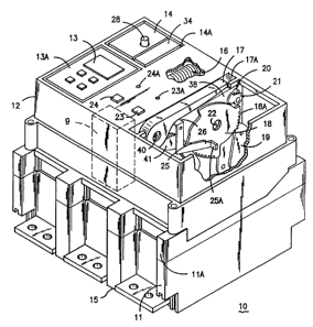
The high ampere-rated circuit breaker 10
shown in Figure 1 is described in U.S. Patent
number 5,424,701 entitled "Operating Mechanism
for High Ampere-rated Circuit Breakers" and is
capable of transferring several thousand amperes
quiescent circuit current at several
CA 02151867 2005-09-30
41PR-7140
- 4 -
hundred volts potential without overheating. The
circuit breaker consists of an electrically insulated
base 11 to which an intermediate cover 11A of similar
insulative material is attached prior to attaching the
top cover 12, also consisting of an electrically-
insulative material. The operating mechanism 9 as
described within the aforementioned U.S. Patent No.
5,424,701 controls the condition of the circuit breaker
contacts. Electrical connection with the interior
current-carrying components is made by load terminal
straps 15 extending from one end of the base and line
terminal straps (not shown) extending from the opposite
end thereof. The interior components are controlled by
an electronic trip unit 13 contained within a recess
13A on the top surface of the top cover 12. The trip
unit 13 is similar to that described within the
aforementioned U.S. Patent 4,672,501 and interacts
further with the bell alarm and lock-out accessory 14
and the undervoltage release accessory 34 contained
within the accessory recess 14A. The reset button 28
extending from the top of the bell alarm and lock-out
accessory serves to provide reset function to the
accessory as well as indication as to whether the
circuit breaker operating mechanism is operative. OPEN
and CLOSE buttons 23, 24 and OPEN and CLOSE indicators
23A, 24A accessible from the top cover allow manual
operation of the circuit breaker operating mechanism
to separate the circuit breaker contacts. An
operating handle 17 within the handle recess 17A
allows the circuit breaker operating mechanism to
be manually reset after automatic separation of the
circuit breaker contacts. The reset button 28 on
CA 02151867 2005-09-30
41PR-7140
- 5 -
the top surface of the bell alarm and lock-out
accessory 14 allows the accessory to be reset as will
be described below.
In the operating mechanism as described within
the U.S. Patent Number 5,486,667 entitled "Rating
Module Unit for High Ampere-rated Circuit Breaker" the
operating handle 17 allows manual operation of the
circuit breaker operating mechanism 9 as well as
providing manual means for charging the operating
mechanism springs 16. The handle 17 is attached to the
operating mechanism sideframe 38 by means of the handle
pivot pin 40 and is connected with the handle drive
gear 18 by a pair of handle drive links 41. The handle
drive gear includes a series of handle drive teeth 18A
that interact with a locking pawl 19 to restrain the
handle drive gear from reverse rotation during the
operating springs charging process as described in the
aforementioned U.S. Patent Number 5,489,755 entitled
"Handle Operator Assembly for High Ampere-rated Circuit
Breaker" and with a two stage operating springs
latching assembly consisting of the primary latch 20
and intermediate latch 21 to prevent rotation of the
closing shaft 22 while the operating springs are being
charged. The circuit breaker lock-out mechanism that
prevents the circuit breaker operating springs
16 from being closed until the bell alarm and
lock-out accessory 14 has been reset by means of
the reset button 28 includes the interlock lever
25 that interacts with the CLOSE button 23 by
means of the U-shaped piece 26 at one end and by
means of the tab 25A that interacts with the
bell alarm and lock-out accessory 14 at the
CA 02151867 2005-09-30
41PR-7140
- 6 -
other end as best seen by referring now to Figure 2.
The interlock lever 25 is viewed from the inside
of the circuit breaker 10 of Figure 1 to detail the U-
shaped piece 26 that interacts with the CLOSE button 23
of Figure 1 by means of the tab 26A. The interlock
lever 25 attaches to the operating mechanism sidewall
38, shown in phantom, by means of the pivot pin 39.
The bell alarm and lock-out accessory 14 and
undervoltage release accessory 34 are shown relative to
the interlock lever 25 to depict the accessory
interlock function via the accessory lever 27. The
position of the accessory lever is determined by the
torsion spring 31 arranged on the spring support 32, as
indicated. The bell alarm and lock-out accessory 14 is
depicted with the reset button 28 extending from the
top thereof and with the plunger 29 extending from the
bottom. As described within the aforementioned U.S.
Patent number 5,502,286 entitled "Bell Alarm and Lock-
out for High Ampere-rated Circuit Breakers", the
position of the plunger 29 is set by the flux shifter
30 which responds to signals from the trip unit 13
(Figure 1) to provide remote indication of the
occurance of a circuit interruption. The undervoltage
release accessory 34 is similar to that described in
U.S. Patent 4,301, 434 entitled "Undervoltage Release
Reset and Lock-out Apparatus" wherein a plunger 35 is
witheld from extending by the solenoid 33 as long as
the voltage applied to the solenoid is above a
predetermined minimum value.
Figure 3 depicts the lock-out condition of the
operating mechanism wherein the plunger 29 from the
bell alarm and lock-out accessory 14 and the
41t , _ , 2151867
~ ..
plunger 35 from the undervoltage release unit 34
contact and drive the accessory lever 27 downwards
against the return bias of the torsion spring 31
which positions the tab 25A in line with the
surface 36A on the side arm 36 of the accessory
lever 27. This prevents the interlock lever 25
from rotating about the pivot 39 when the CLOSE
button 23 of Figure 1 is depressed. As described
earlier, the CLOSE button interacts with the
interlock lever by means of the U-shaped piece 26
to otherwise cause the rotation of the interlock
lever when the CLOSE button is depressed.
Figure 4 depicts the unlocked-out or "free"
condition wherein the plunger 29 from the bell
alarm and lock-out accessory 14 and the plunger 35
from the undervoltage release unit 34 are away from
the accessory lever 27. The reset button 28 on the
bell alarm and lock-out accessory has been
depressed to withdraw the plunger 29 and the proper
voltage has been applied to the solenoid 33 in the
undervoltage release unit 34. The accessory lever
is returned to the home position by the return bias
of the torsion spring 31, the tab 25A is now out of
line with the surface 36A on the side arm 36 of the
accessory lever 27. This allows the interlock
lever 25 to rotate about the pivot 39 from the
interlocked position shown in phantom when the
CLOSE button 23 of Figure 1 is depressed
A circuit breaker lock-out mechansim has
herein been described that interfaces between the
circuit breaker operating mechansim and the circuit
breaker accessory to prevent the operating
mechanism from responding to close the circuit
breaker contacts until and unless the accessories
are reset.