Language selection

Search

Patent 2151964 Summary

Third-party information liability

Some of the information on this Web page has been provided by external sources. The Government of Canada is not responsible for the accuracy, reliability or currency of the information supplied by external sources. Users wishing to rely upon this information should consult directly with the source of the information. Content provided by external sources is not subject to official languages, privacy and accessibility requirements.

Claims and Abstract availability

Any discrepancies in the text and image of the Claims and Abstract are due to differing posting times. Text of the Claims and Abstract are posted:

  • At the time the application is open to public inspection;
  • At the time of issue of the patent (grant).
(12) Patent Application: (11) CA 2151964
(54) English Title: DEVICE FOR JOINTS IN CONCRETE FLOORS
(54) French Title: DISPOSITIF SERVANT POUR LES JOINTS DANS LES PLANCHERS DE BETON
Status: Deemed Abandoned and Beyond the Period of Reinstatement - Pending Response to Notice of Disregarded Communication
Bibliographic Data
(51) International Patent Classification (IPC):
  • E04F 15/14 (2006.01)
  • E01C 11/02 (2006.01)
  • E01C 11/14 (2006.01)
(72) Inventors :
  • JONSSON, SVEN-GUNNAR (Sweden)
(73) Owners :
  • SVEN-GUNNAR JONSSON
(71) Applicants :
(74) Agent: SWABEY OGILVY RENAULT
(74) Associate agent:
(45) Issued:
(86) PCT Filing Date: 1993-11-29
(87) Open to Public Inspection: 1994-06-23
Availability of licence: N/A
Dedicated to the Public: N/A
(25) Language of filing: English

Patent Cooperation Treaty (PCT): Yes
(86) PCT Filing Number: PCT/SE1993/001026
(87) International Publication Number: SE1993001026
(85) National Entry: 1995-06-15

(30) Application Priority Data:
Application No. Country/Territory Date
9203802-5 (Sweden) 1992-12-17

Abstracts

English Abstract


A device for joints in concrete floors is disclosed, comprising edge linings (1) and one or more clasps (2). The clasps (2) and the
edge linings (1) are interconnected in a fixed manner, and each clasp (2) is designed as two laterally projecting arches (3) which join in a
downwardly extending, arcuate projection (4). Moreover, a method for casting concrete floors is disclosed, comprising the steps of casting
the concrete floor on the base and steel trowelling of the concrete surface. The device is pressed down in the concrete before hardening
thereof, whereupon the edge linings (1) are adjusted in the steel trowelling of the concrete surface. The concrete floor is sawn between the
edge linings (1) to a depth which is smaller than the depth of the clasps (2), whereupon the now formed joints are filled with a semi-elastic
compound. Furthermore, means for pressing down or mounting of the device, and a casting method in which the device is mounted in situ
before casting are disclosed.


Claims

Note: Claims are shown in the official language in which they were submitted.

6
CLAIMS
1. Device for joints in concrete floors which are
made as industrial products, said device comprising edge
linings (1) and one or more clasps (2), c h a r a c -
t e r i s e d in that said edge linings (1) and said
clasps (2) are interconnected in a fixed manner, and
that each clasp (2) is designed as two laterally pro-
jecting arches (3) which join in an arcuate, downwardly
extending projection (4).
2. Means for pressing down the device according to
claim 1 in the concrete, c h a r a c t e r i s e d in
that said means comprises a spear (7) having at least
one spear head (8) and mounting means (9) having a
clamping function (10) for fixing the device according
to claim 1.
3. Means for mounting the device according to claim
1 before casting of the concrete floor, c h a r a c -
t e r i s e d in that said means comprises a cup-shaped
recess (12) for the arcuate projection (4) of said
clasps (2), a recess (13) for receiving the edge linings
(1) and a recess (14) for the laterally projecting
arches (3) of said clasps (2), and a base portion (15).
4. Method for casting concrete floors which are
made as industrial products, said method comprising the
steps of casting the concrete floor on the base and
steel trowelling of the concrete surface, c h a r a c -
t e r i s e d in that the device according to claim 1
is pressed down in the concrete before hardening there-
of, the edge linings (1) are adjusted in the steel
trowelling operation, and the concrete floor is sawn
between the edge linings (1) so deep that the cut
reaches down in the arcuate projection (4), but not so
deep that the clasps (2) are sawn apart, whereupon the
sawn-up joints are filled with a semi-elastic compound.

5. Method for casting concrete floors according to
claim 4, c h a r a c t e r i s e d in that the device
according to claim 1 is pressed down in the concrete by
means of at least one means according to claim 2.
6. Method for casting concrete floors which are
made as industrial products, said method comprising the
steps of casting the concrete floor on the base and
steel trowelling thereof, c h a r a c t e r i s e d in
that the device according to claim 1 is mounted on the
means according to claim 3 before said casting of the
concrete floor and steel trowelling thereof, the con-
crete floor is sawn between the edge linings (1) so deep
that the cut reaches down in the arcuate projection (4),
but not so deep that said clasps are sawn apart, where-
upon the sawn-up joints are filled with a semi-elastic
compound.

Description

Note: Descriptions are shown in the official language in which they were submitted.


WO94/13906 215 ~ PCT/SE93/01026
.
~EVICE FOR JOINTS IN CONCRETE FLOORS
The present invention relates to a device for
joints in concrete floors, and a casting method in which
the device is used.
In the process of making a large-surface concrete
floor, there is always a risk of shrinkage cracks. By
joint spacing of the concrete slab attempts have been
made to avoid such cracks. When making concrete floors,
both traditionally reinforced floors and fibre-rein-
forced concrete floors, these joints have lately been
sawn after casting and hardening of the concrete, fol-
lowed by filling the joints with a semi-elastic sealing
compound. However, the joints are not protected against
mechanical damage and are easily damaged by e.g. truck
traffic. Edge linings have been made in expansion
joints, said linings being mounted in the bulkheads of
the joints, but this is too expensive and takes too much
time to be used on a large scale.
A further problem arising in joint spacing is that
the concrete slabs rise and are pressed down differently
when mechanically damaged, thereby causing differences
in level between the concrete slabs. In order to try to
prevent such differences, dowels are normally used which
are cast into one slab part and which in the other slab
part are coated with bitumen to allow sliding.
One object of the present invention is to provide a
device for joints in concrete floors, by means of which
the problems with shrinkage cracks, damaged joint edges
and differences in level between the concrete slabs are
avoided.
A further object of the present invention is to
provide means for mounting the device according to the
present invention in the concrete floor.

WO94/13906 ~ S 19 ~ ~ PCT/SE93/01026
.
One more object of the present invention is to pro-
vide a method for casting concrete floors, in which the
device according to the invention is used.
These problems with shrinkage cracks, damaged joint
edges and differences in level between the slabs are
solved by means of the device, the means and the method
as claimed in claims 1-6.
Briefly, the present invention thus relates to a
device for joints in concrete floors, which comprises
edge linings with clasps. According to the present
invention, the clasps and the edge linings are intercon-
nected in a fixed manner, and each clasp is designed as
two laterally projecting arches which join in an
arcuate, downwardly extending projection.
The present invention also relates to a means for
pressing down the device for joints in concrete floors,
and a means for mounting the device for joints in con-
crete floors before casting the concrete floor.
Moreover, the present invention relates to a method
for casting concrete floors, comprising the steps of
casting the concrete floor on the base and steel trowel-
ling of the floor surface. According to the present
invention, the device according to claim 1 is pressed
down in the concrete before hardening thereof, whereupon
the edge linings are adjusted in the steel trowelling of
the concrete surface. The concrete floor is sawn between
the edge linings to a depth which is smaller than the
depth of the clasps, whereupon the now formed joints are
filled with a semi-elastic sealing compound.
The present invention also relates to a method in
which the device for joints in concrete floors is
mounted on means in the form of trestles, whereupon the
concrete floor is cast and steel trowelled. The concrete
floor is sawn between the edge linings to a depth which
is smaller than the depth of the clasps, whereupon the

WO94/13906 21~19 6 4 PCT/SE93/01026
now formed joints are filled with a semi-elastic sealing
compound.
Preferred embodiments of the device and the means
according to the present invention will be described
below with reference to the accompanying drawings. These
embodiments must not be considered restrictive for the
scope of the present invention.
Fig. 1 is a top plan view of a preferred embodiment
of the device for joints in concrete floors according to
the present invention.
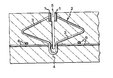
Fig. 2 is a cross-sectional view of a preferred
embodiment of the device for joints in concrete floors
according to the present invention in a reinforced con-
crete floor.
Fig. 3 is a top plan view of a preferred embodiment
of a means for pressing down the device for joints in
concrete floors.
Fig. 4 is a side view of the means for pressing
down the device for joints in the concrete floor.
Fig. 5 is a top plan view of a preferred embodiment
of a means for mounting the device for joints before
casting the concrete.
Fig. 6 is a side view of the means for mounting the
device for joints before casting the concrete floor.
The embodiment of the device for joints in concrete
floors according to the present invention as illustrated
in Figs 1 and 2 comprises edge linings 1 and one or more
clasps 2, the clasps 2 being attached to the edge lin-
ings 1. Thus, the edge linings 1 are fixed relative to
each other. The clasps 2 are designed as two laterally
projecting, V-shaped arches 3 which join in a downwardly
extending, U-shaped projection 4.
The inventive device is used when casting concrete
floors, in which process the device is pressed down in
the concrete before hardening. The concrete floor is
steel trowelled and then also the edge linings 1 are

WO94/13906 PCT/SE93/01026
~151~4 ~
adjusted. After a few days, a joint 5 is cut in the con-
crete floor between the edge linings 1. The joint 5 is
made so deep that it extends into the U-shaped projec-
tion 4 and through the reinforcement 6 of the concrete
floor, but not so deep that the clasps 2 are sawn apart.
This joint 5 is then filled with an elastic compound.
Since the clasps 2 are bent as shown in Fig. 2, the
shrinkage of the area divided by the joints 5 can take
place without the clasps 2 being damaged or preventing
shrinkage. Cracks do not arise during shrinkage since
the slab parts on each side of the sawn-up joint are
allowed to shrink without resistance from the other ele-
ments included in the concrete. No difference in level
is possible between the edge linings 1, since the edge
linings 1 are kept in a fixed position relative to each
other by means of the projections 4 of the clasps 2.
The embodiment shown in Figs 3 and 4 of a means for
pressing down the device in Figs 1 and 2 in the concrete
floor comprises a spear 7 with at least one spear head 8
and fastening means 9 having a clamping function 10 for
fixing the device in Figs 1 and 2. The pressing-down
means is also fitted with a handle 11 at the top of the
spear 7.
The pressing-down means is used when the device in
Figs 1 and 2 should be pressed down in the cast con-
crete. Such pressing-down means permit vertical and
horizontal adjusting of the edge linings and fixing
thereof in the correct position.
The embodiment shown in Figs 5 and 6 of a means for
mounting the device in Figs 1 and 2 before casting of
the concrete floor comprises a cup-shaped recess 12 for
the arcuate projections 4 of the clasps 2, a recess 13
for receiving the edge linings 1 and a recess 14 for the
laterally projecting arches 3 of the clasps 2, and a
base portion 15.

WO94113906 21~ i 9 6 4 PCT/SE93101026
The mounting means is used when the device in Figs
1 and 2 is mounted in situ before casting of the con-
crete floor. The mounting means can also be fixed to the
base by "local" concrete blocks which are cast round the
base portion 15 of the mounting means.

Representative Drawing
A single figure which represents the drawing illustrating the invention.
Administrative Status

2024-08-01:As part of the Next Generation Patents (NGP) transition, the Canadian Patents Database (CPD) now contains a more detailed Event History, which replicates the Event Log of our new back-office solution.

Please note that "Inactive:" events refers to events no longer in use in our new back-office solution.

For a clearer understanding of the status of the application/patent presented on this page, the site Disclaimer , as well as the definitions for Patent , Event History , Maintenance Fee  and Payment History  should be consulted.

Event History

Description Date
Inactive: IPC from MCD 2006-03-11
Time Limit for Reversal Expired 1997-12-01
Application Not Reinstated by Deadline 1997-12-01
Deemed Abandoned - Failure to Respond to Maintenance Fee Notice 1996-11-29
Application Published (Open to Public Inspection) 1994-06-23

Abandonment History

Abandonment Date Reason Reinstatement Date
1996-11-29
Owners on Record

Note: Records showing the ownership history in alphabetical order.

Current Owners on Record
SVEN-GUNNAR JONSSON
Past Owners on Record
None
Past Owners that do not appear in the "Owners on Record" listing will appear in other documentation within the application.
Documents

To view selected files, please enter reCAPTCHA code :


To view images, click a link in the Document Description column. To download the documents, select one or more checkboxes in the first column and then click the "Download Selected in PDF format (Zip Archive)" or the "Download Selected as Single PDF" button.

List of published and non-published patent-specific documents on the CPD .

If you have any difficulty accessing content, you can call the Client Service Centre at 1-866-997-1936 or send them an e-mail at CIPO Client Service Centre.


Document
Description 
Date
(yyyy-mm-dd) 
Number of pages   Size of Image (KB) 
Description 1994-06-22 5 194
Abstract 1994-06-22 1 37
Claims 1994-06-22 2 69
Drawings 1994-06-22 3 36
Representative drawing 1999-05-30 1 15
Fees 1995-06-14 1 49
International preliminary examination report 1995-06-14 9 277