Sélection de la langue

Search

Sommaire du brevet 2151964 

Énoncé de désistement de responsabilité concernant l'information provenant de tiers

Une partie des informations de ce site Web a été fournie par des sources externes. Le gouvernement du Canada n'assume aucune responsabilité concernant la précision, l'actualité ou la fiabilité des informations fournies par les sources externes. Les utilisateurs qui désirent employer cette information devraient consulter directement la source des informations. Le contenu fourni par les sources externes n'est pas assujetti aux exigences sur les langues officielles, la protection des renseignements personnels et l'accessibilité.

Disponibilité de l'Abrégé et des Revendications

L'apparition de différences dans le texte et l'image des Revendications et de l'Abrégé dépend du moment auquel le document est publié. Les textes des Revendications et de l'Abrégé sont affichés :

  • lorsque la demande peut être examinée par le public;
  • lorsque le brevet est émis (délivrance).
(12) Demande de brevet: (11) CA 2151964
(54) Titre français: DISPOSITIF SERVANT POUR LES JOINTS DANS LES PLANCHERS DE BETON
(54) Titre anglais: DEVICE FOR JOINTS IN CONCRETE FLOORS
Statut: Réputée abandonnée et au-delà du délai pour le rétablissement - en attente de la réponse à l’avis de communication rejetée
Données bibliographiques
Abrégés

Abrégé anglais


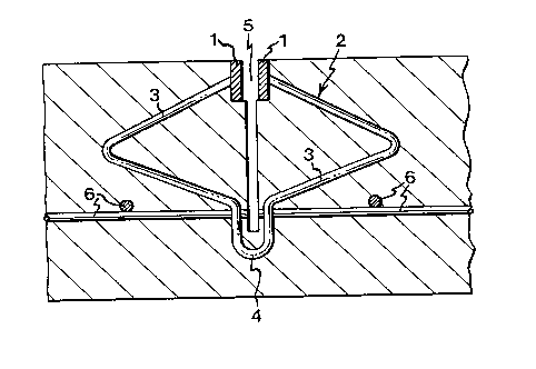
A device for joints in concrete floors is disclosed, comprising edge linings (1) and one or more clasps (2). The clasps (2) and the
edge linings (1) are interconnected in a fixed manner, and each clasp (2) is designed as two laterally projecting arches (3) which join in a
downwardly extending, arcuate projection (4). Moreover, a method for casting concrete floors is disclosed, comprising the steps of casting
the concrete floor on the base and steel trowelling of the concrete surface. The device is pressed down in the concrete before hardening
thereof, whereupon the edge linings (1) are adjusted in the steel trowelling of the concrete surface. The concrete floor is sawn between the
edge linings (1) to a depth which is smaller than the depth of the clasps (2), whereupon the now formed joints are filled with a semi-elastic
compound. Furthermore, means for pressing down or mounting of the device, and a casting method in which the device is mounted in situ
before casting are disclosed.

Revendications

Note : Les revendications sont présentées dans la langue officielle dans laquelle elles ont été soumises.


6
CLAIMS
1. Device for joints in concrete floors which are
made as industrial products, said device comprising edge
linings (1) and one or more clasps (2), c h a r a c -
t e r i s e d in that said edge linings (1) and said
clasps (2) are interconnected in a fixed manner, and
that each clasp (2) is designed as two laterally pro-
jecting arches (3) which join in an arcuate, downwardly
extending projection (4).
2. Means for pressing down the device according to
claim 1 in the concrete, c h a r a c t e r i s e d in
that said means comprises a spear (7) having at least
one spear head (8) and mounting means (9) having a
clamping function (10) for fixing the device according
to claim 1.
3. Means for mounting the device according to claim
1 before casting of the concrete floor, c h a r a c -
t e r i s e d in that said means comprises a cup-shaped
recess (12) for the arcuate projection (4) of said
clasps (2), a recess (13) for receiving the edge linings
(1) and a recess (14) for the laterally projecting
arches (3) of said clasps (2), and a base portion (15).
4. Method for casting concrete floors which are
made as industrial products, said method comprising the
steps of casting the concrete floor on the base and
steel trowelling of the concrete surface, c h a r a c -
t e r i s e d in that the device according to claim 1
is pressed down in the concrete before hardening there-
of, the edge linings (1) are adjusted in the steel
trowelling operation, and the concrete floor is sawn
between the edge linings (1) so deep that the cut
reaches down in the arcuate projection (4), but not so
deep that the clasps (2) are sawn apart, whereupon the
sawn-up joints are filled with a semi-elastic compound.

5. Method for casting concrete floors according to
claim 4, c h a r a c t e r i s e d in that the device
according to claim 1 is pressed down in the concrete by
means of at least one means according to claim 2.
6. Method for casting concrete floors which are
made as industrial products, said method comprising the
steps of casting the concrete floor on the base and
steel trowelling thereof, c h a r a c t e r i s e d in
that the device according to claim 1 is mounted on the
means according to claim 3 before said casting of the
concrete floor and steel trowelling thereof, the con-
crete floor is sawn between the edge linings (1) so deep
that the cut reaches down in the arcuate projection (4),
but not so deep that said clasps are sawn apart, where-
upon the sawn-up joints are filled with a semi-elastic
compound.

Description

Note : Les descriptions sont présentées dans la langue officielle dans laquelle elles ont été soumises.

WO94/13906 215 ~ PCT/SE93/01026
.
~EVICE FOR JOINTS IN CONCRETE FLOORS
The present invention relates to a device for
joints in concrete floors, and a casting method in which
the device is used.
In the process of making a large-surface concrete
floor, there is always a risk of shrinkage cracks. By
joint spacing of the concrete slab attempts have been
made to avoid such cracks. When making concrete floors,
both traditionally reinforced floors and fibre-rein-
forced concrete floors, these joints have lately been
sawn after casting and hardening of the concrete, fol-
lowed by filling the joints with a semi-elastic sealing
compound. However, the joints are not protected against
mechanical damage and are easily damaged by e.g. truck
traffic. Edge linings have been made in expansion
joints, said linings being mounted in the bulkheads of
the joints, but this is too expensive and takes too much
time to be used on a large scale.
A further problem arising in joint spacing is that
the concrete slabs rise and are pressed down differently
when mechanically damaged, thereby causing differences
in level between the concrete slabs. In order to try to
prevent such differences, dowels are normally used which
are cast into one slab part and which in the other slab
part are coated with bitumen to allow sliding.
One object of the present invention is to provide a
device for joints in concrete floors, by means of which
the problems with shrinkage cracks, damaged joint edges
and differences in level between the concrete slabs are
avoided.
A further object of the present invention is to
provide means for mounting the device according to the
present invention in the concrete floor.

WO94/13906 ~ S 19 ~ ~ PCT/SE93/01026
.
One more object of the present invention is to pro-
vide a method for casting concrete floors, in which the
device according to the invention is used.
These problems with shrinkage cracks, damaged joint
edges and differences in level between the slabs are
solved by means of the device, the means and the method
as claimed in claims 1-6.
Briefly, the present invention thus relates to a
device for joints in concrete floors, which comprises
edge linings with clasps. According to the present
invention, the clasps and the edge linings are intercon-
nected in a fixed manner, and each clasp is designed as
two laterally projecting arches which join in an
arcuate, downwardly extending projection.
The present invention also relates to a means for
pressing down the device for joints in concrete floors,
and a means for mounting the device for joints in con-
crete floors before casting the concrete floor.
Moreover, the present invention relates to a method
for casting concrete floors, comprising the steps of
casting the concrete floor on the base and steel trowel-
ling of the floor surface. According to the present
invention, the device according to claim 1 is pressed
down in the concrete before hardening thereof, whereupon
the edge linings are adjusted in the steel trowelling of
the concrete surface. The concrete floor is sawn between
the edge linings to a depth which is smaller than the
depth of the clasps, whereupon the now formed joints are
filled with a semi-elastic sealing compound.
The present invention also relates to a method in
which the device for joints in concrete floors is
mounted on means in the form of trestles, whereupon the
concrete floor is cast and steel trowelled. The concrete
floor is sawn between the edge linings to a depth which
is smaller than the depth of the clasps, whereupon the

WO94/13906 21~19 6 4 PCT/SE93/01026
now formed joints are filled with a semi-elastic sealing
compound.
Preferred embodiments of the device and the means
according to the present invention will be described
below with reference to the accompanying drawings. These
embodiments must not be considered restrictive for the
scope of the present invention.
Fig. 1 is a top plan view of a preferred embodiment
of the device for joints in concrete floors according to
the present invention.
Fig. 2 is a cross-sectional view of a preferred
embodiment of the device for joints in concrete floors
according to the present invention in a reinforced con-
crete floor.
Fig. 3 is a top plan view of a preferred embodiment
of a means for pressing down the device for joints in
concrete floors.
Fig. 4 is a side view of the means for pressing
down the device for joints in the concrete floor.
Fig. 5 is a top plan view of a preferred embodiment
of a means for mounting the device for joints before
casting the concrete.
Fig. 6 is a side view of the means for mounting the
device for joints before casting the concrete floor.
The embodiment of the device for joints in concrete
floors according to the present invention as illustrated
in Figs 1 and 2 comprises edge linings 1 and one or more
clasps 2, the clasps 2 being attached to the edge lin-
ings 1. Thus, the edge linings 1 are fixed relative to
each other. The clasps 2 are designed as two laterally
projecting, V-shaped arches 3 which join in a downwardly
extending, U-shaped projection 4.
The inventive device is used when casting concrete
floors, in which process the device is pressed down in
the concrete before hardening. The concrete floor is
steel trowelled and then also the edge linings 1 are

WO94/13906 PCT/SE93/01026
~151~4 ~
adjusted. After a few days, a joint 5 is cut in the con-
crete floor between the edge linings 1. The joint 5 is
made so deep that it extends into the U-shaped projec-
tion 4 and through the reinforcement 6 of the concrete
floor, but not so deep that the clasps 2 are sawn apart.
This joint 5 is then filled with an elastic compound.
Since the clasps 2 are bent as shown in Fig. 2, the
shrinkage of the area divided by the joints 5 can take
place without the clasps 2 being damaged or preventing
shrinkage. Cracks do not arise during shrinkage since
the slab parts on each side of the sawn-up joint are
allowed to shrink without resistance from the other ele-
ments included in the concrete. No difference in level
is possible between the edge linings 1, since the edge
linings 1 are kept in a fixed position relative to each
other by means of the projections 4 of the clasps 2.
The embodiment shown in Figs 3 and 4 of a means for
pressing down the device in Figs 1 and 2 in the concrete
floor comprises a spear 7 with at least one spear head 8
and fastening means 9 having a clamping function 10 for
fixing the device in Figs 1 and 2. The pressing-down
means is also fitted with a handle 11 at the top of the
spear 7.
The pressing-down means is used when the device in
Figs 1 and 2 should be pressed down in the cast con-
crete. Such pressing-down means permit vertical and
horizontal adjusting of the edge linings and fixing
thereof in the correct position.
The embodiment shown in Figs 5 and 6 of a means for
mounting the device in Figs 1 and 2 before casting of
the concrete floor comprises a cup-shaped recess 12 for
the arcuate projections 4 of the clasps 2, a recess 13
for receiving the edge linings 1 and a recess 14 for the
laterally projecting arches 3 of the clasps 2, and a
base portion 15.

WO94113906 21~ i 9 6 4 PCT/SE93101026
The mounting means is used when the device in Figs
1 and 2 is mounted in situ before casting of the con-
crete floor. The mounting means can also be fixed to the
base by "local" concrete blocks which are cast round the
base portion 15 of the mounting means.

Dessin représentatif
Une figure unique qui représente un dessin illustrant l'invention.
États administratifs

2024-08-01 : Dans le cadre de la transition vers les Brevets de nouvelle génération (BNG), la base de données sur les brevets canadiens (BDBC) contient désormais un Historique d'événement plus détaillé, qui reproduit le Journal des événements de notre nouvelle solution interne.

Veuillez noter que les événements débutant par « Inactive : » se réfèrent à des événements qui ne sont plus utilisés dans notre nouvelle solution interne.

Pour une meilleure compréhension de l'état de la demande ou brevet qui figure sur cette page, la rubrique Mise en garde , et les descriptions de Brevet , Historique d'événement , Taxes périodiques et Historique des paiements devraient être consultées.

Historique d'événement

Description Date
Inactive : CIB de MCD 2006-03-11
Le délai pour l'annulation est expiré 1997-12-01
Demande non rétablie avant l'échéance 1997-12-01
Réputée abandonnée - omission de répondre à un avis sur les taxes pour le maintien en état 1996-11-29
Demande publiée (accessible au public) 1994-06-23

Historique d'abandonnement

Date d'abandonnement Raison Date de rétablissement
1996-11-29
Titulaires au dossier

Les titulaires actuels et antérieures au dossier sont affichés en ordre alphabétique.

Titulaires actuels au dossier
SVEN-GUNNAR JONSSON
Titulaires antérieures au dossier
S.O.
Les propriétaires antérieurs qui ne figurent pas dans la liste des « Propriétaires au dossier » apparaîtront dans d'autres documents au dossier.
Documents

Pour visionner les fichiers sélectionnés, entrer le code reCAPTCHA :


Pour visualiser une image, cliquer sur un lien dans la colonne description du document. Pour télécharger l'image (les images), cliquer l'une ou plusieurs cases à cocher dans la première colonne et ensuite cliquer sur le bouton "Télécharger sélection en format PDF (archive Zip)" ou le bouton "Télécharger sélection (en un fichier PDF fusionné)".

Liste des documents de brevet publiés et non publiés sur la BDBC .

Si vous avez des difficultés à accéder au contenu, veuillez communiquer avec le Centre de services à la clientèle au 1-866-997-1936, ou envoyer un courriel au Centre de service à la clientèle de l'OPIC.


Description du
Document 
Date
(aaaa-mm-jj) 
Nombre de pages   Taille de l'image (Ko) 
Description 1994-06-22 5 194
Abrégé 1994-06-22 1 37
Revendications 1994-06-22 2 69
Dessins 1994-06-22 3 36
Dessin représentatif 1999-05-30 1 15
Taxes 1995-06-14 1 49
Rapport d'examen préliminaire international 1995-06-14 9 277