Note: Descriptions are shown in the official language in which they were submitted.
2152111
AUTOMOBn .F. V~ T T~M DETER~F.~T DEVIOE
Field of th. Invention
This invention, referred to hereinafter as the "Biff StickTM" window
bar, relates to a device for det~rring automobile v~n~ m, particularly
carjacking.
B~cl~ound of the Invelltiol~
An open car window provides convenient access to the interior of a
vehicle for someone intent upon reaching into the vehicle to remove an
object or for access to a person sitting in the vehicle. While this type of
access is often a conveniel-re, it also provides an entry port for acts of
vandalism on occ~lpal1ts and objects inside. The related art discussed below
does not address this concern, or is impractical for the application described
herein.
U.S. Patent No. 3,204,981 describes a removable window guard
comprising an elongated element of spring steel or other slightly elastic, but
form ret~ining, m~t~ ri~l which is bent into a configuration subst~nti~lly
blocking the window opening when the device is positioned in the window
frame.
U.S. Patent No. 4,653,562 relates to an automobile window guard
which permits ventilation when the window is open, but prevents projection
of animal or human e~ Glllities through the area covered by the guard. The
device is made of two comple~ screen elongate m~mhers which
slidably fit into a frame which then fits into the window frame of the
vehicle.
U.S. Patent No. 4,854,364 describes a pet barrier which is readily
adaptable to various vehicle window shapes by reason of a mllltitllde of
horizontally adjustable " ~P ~ which abut opposile window frame
locations. These elongate members are su~polled by spring biased upright
posts which interconnect the main horizontal members for secllring the
barrier in the window frame.
Each of the devices described in the above referenced patents is
inten~ed to keep oc ;ùp~ of the vehicle captive therein when the vehicle's
window is in an open position, and in addition, are buLkier, require more
time to install and remove, and are not as conveniently storable as the Biff
StickTM window bar.
- 2ls2lll
Accordingly, the inventor has recognized a need for a strong, light
weight, highly visible device which is selectively positionable in the channel
of an automobile window frame; which is easily inct~ hle and removable;
which is unobstructive to the act of driving; and which is conveniently
5 storable when not in use.
Su~ of the Inv~ntion
According to the invention, a device for detçrring automobile
v~n~ m by releasably çngaging and traversing a window receiving
channel in an automobile, compri~es a first elongate member inchl~ling an
10 arcuate, blade shaped window channel-erlgaging end and a non window
channel-çngaging, or plain, end, and a second elongate ~ ,..h,l including
an arcuate, blade shaped window channel-engaging end and a non window
channel-engaging, or plain, end, in which the non window channel-
eng~ging end and a variable portion of the second elongate member is
15 telescopically engaged with the first elongate lllelllber, further in which the
variable portion of the second elongate mPmh~r has a length that is
releasably fixable with respect to the first elongate ...~,..her, whe~tby the
overall length of the device can be adjusted to engage opposite locations in
window &ames of various sizes. As assembled, the tips of the blade shaped
20 ends can be positioned coplanar and are not collinear with a common
longibl~lin~l axis of the elongate ~"~".ker, wlle~ the opposed, arcuate ends
displace the elongate Ill~lllhl;~S a sllfflci~nt ~ e away from a
windowpane occuwing the channel when the device is in~t~lled in the
window frame so that use of the device is possible regardless of whether the
25 window is open or closed.
In one embo lim~nt of the invention, a bushing mounted on the plain
end of the first elongate lll~lllber is employed for varying and fixing the
length of the device. The bushing includes at least one sidewall having a
bore theletlllough for receiving a threaded stud which engages the side wall
30 of the telescopically received second elongate mPmher, for releasably fixing
the device at the a~prop.iate length.
In a dirr~ ~."lt aspect of this embodiment, the first elongate lll~lllb~,
also has a hole in the side wall thereof near the plain end which is aligned
with the bores in the bushing side walls to receive the,ellll~o~lgh the threaded35 stud for fixing the length of the device.
2l52lll
In another embodiment, a biasing means such as a spring, for
example, is disposed in the first elongate m~mher between the blade shaped
end and the plain end. The plain end of the second elongate member is
flared and, optionally, fitted with a plug, and is telescopically received in the
5 first elongate member; the plugged, flared end surface thus eng~ging an end
of the spring in the first elongate member.
In one aspect of this embo~lim~nt, the first elongate member is
çrimred to make its inner tli~"~ tl-- at the ~rimred location smaller than the
outer rli~m~.t~.r of the flared end of the second elongate lllelllber, as a means
10 for preventing ~i~e.~g~gement of the two elongate members due to the
restoring force of the spring.
In another aspect of the invention, either of the bushing components
described in the former embodiment may be il~co~ led as optional
l~info~ g means for the device, and for fixing the length of the device to
15 accommodate vehicle window frames of varying sizes.
It will be appreciated that the means for varying and fLlLing the length
of the device is not intP.n~ed to be limited to the bushing assembly as
cl~im~.~l, but may comprise such other m~.~.h~ni~m~ including a tapered,
elongate mP.mher and a threaded nut, or sleeve, engaged with at least one of
20 the elongate members at the telescopic juncture of the members, wherein, as
is known in the art, the nut or sleeve has a tapering inner ~i~m-~.t~.r to engage
the tapered elongate lllelllber depending upon the rotation direction of the
nut/sleeve. All~.llali~,ly, one of the elongate Illrl~ could have a series
of holes eng~E~ble with a locking bar; or detents eng~g~ble with a biased
25 catch located on the other elongate . . I~.ll .h~.., for releasably fixing the length
of the device to fit various window frames.
In each aspect of the invention clesçribed above, the blade shaped
ends of the Biff StickTM window bar are suffiçiently flattened to engage the
window ch~nn~.l without twisting. In addition, the arcuate design of the
30 blade shaped ends displaces the elongate members a sufficient rli~t~nce from
the windowpane when the vehicle window is closed so that the Biff StickTM
window bar can be used regardless of whether the window is open or
closed.
It is therefore an object of this invention to provide a device for
35 thwarting automobile v~n~ m which can be in~t~llPd to traverse a vehicle
window frame when the window is opened or closed.
21 5211 1
It is another object of the invention to provide a strong, rigid, light
weight and highly visible device for positioning in the window frame of a
vehicle to deter would be vandals from çntPring the vehicle through the
window.
S It is another object of the invention to provide a device as in~1ic~tPcl
above which can be quickly and easily installed and removed, and
conveniently stored when not in use.
These and other objects and advantages of the invention will become
more appalellt when viewed with the drawings and the detailed description
which follow.
Description of thP Drawir~.c
Figure 1 is a s~h~ ic, side elevational view of a Biff StickTM
window bar in.ct~lle~ in an automobile driver's side window frame.
Figure 2 is a side elevational view of the Biff StickTM window bar
showing the relationship b~t~ n the arcuate, blade shaped ends of the
device and the elongate body of the device.
Figure 3 is an exploded cutaway view of an embodiment of the Biff
StickTM window bar showing one aspect of the bushing in which the
bushing collar fits substantially over the plain end of the first elongate
member.
Figure 4 shows an aspect of the bushing in which the bushing collar
extends past the plain end of the first elongate member.
Figure S shows another embodiment of the Biff StickTM window bar
in which the second elongate member is spring biased within the first
elongate ~ .llb~l, and
Figure 6 is an enlarged view of the Biff StickTM window bar
embodiment of Figure S showing the flared end of the second elongate
member, and the first elongate member inClll~ing a crimp for ret~ining the
second elongate lllenlber against the restoring force of the biasing means.
Detailed Descri~tion of thP Tnv~ntion
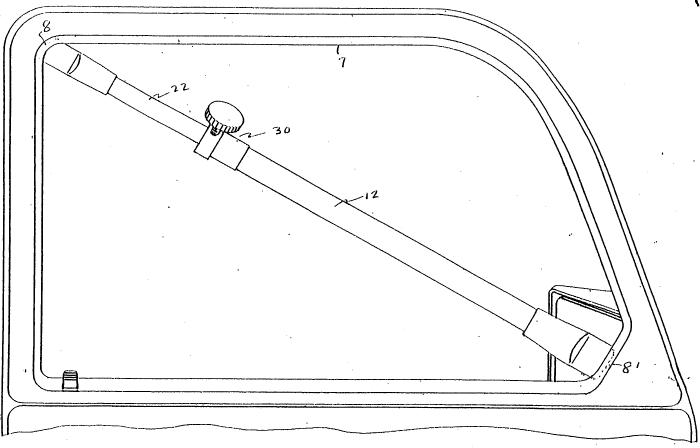
In one embodiment of the invention 10, as shown in Figures 1-3,
the Biff StickTM window bar cornrri~eS a first elongate member 12 having a
plain end 18 and an arcuate, blade shaped end 14. A second elongate
member 22 has a plain end 28 and an arcuate, blade shaped end 24, similar
to that of the first elongate ~l. .llkcl. The first elongate ~ .her 12 has an
inner ~ mPtP.r s~lffiri~nt to slidably receive the plain end 28 and a body
21 5211 1
portion 23 of the second elongate member therein such that the blade shaped
ends 14, 24 are opposed. As shown in Figure 2, the tips of the blade
shaped ends 14, 24 can be positioned coplanar, and are not collinear with a
cornmon longit~ldin~l axis 26 of the elongate lllem~l~. The arcuate nature of
5 the blade shaped ends 14 and 24 ~ pl~es the body of the Biff StickTM
window bar snfficiently away from the vehicle window so that the device
can be used when the window is either open or closed. The Biff SticklM
window bar further inchldes means for varying and fixing the length of the
device when the first and second elongate members 12, 22 are engaged as
10 described above, to allow the blade shaped ends 14, 24 to securely engage
opposite locations 8, 8' in the vehicle window frame channel 7.
In one aspect of the invention, the means for varying and fixing the
length of the Biff StickTM window bar includes a bushing 30 mounted over
the plain end 18 of the first elongate member 12. The bushing 30 has an
15 inner side wall 80 which slides inside the plain end 18 of the first elongatemember 12, and an outer side wall 82 having a length shorter than that of
the inner side wall 80, which slides over the outside of plain end 18. The
bushing 30 has a bore through the inner and outer side walls 80, 82 for
receiving a threaded stud 34 inclutling a thumb knob 36 mounted on one end
20 of the stud 34. In one embo-lim~nt, the side wall 72 of the first elongate
member 12 has a hole adja~çnt the plain end 18 which is aligned with the
bore 72 in the bushing when the bushing is fully seated on the plain end of
the first elongate m~mher. When the Biff StickTM window bar is e.xtç~de~l
to its desired length, the threaded stud 34, engaged in the bore in the
25 bushing and the hole in the sidewall, is rotated via the thumbscrew until a
first end of the stud contacts the sidewall of the second elongate member
22, thus fixing its position with respect to the first elongate member.
In another aspect of the invention, the bushing, as shown in Figure
4, fits into and over the plain end 18 of the first elongate member 12 as
30 described above, but does not seat against the plain end, leaving that portion
of the bushing having a hole through its sidewalls ~ g past the plain
end of the first elongate ."~ "1~- . Accordingly, the first elongate m~mh~r 12
is not required to have a hole in a side wall thereof near the plain end and
aligned with the hole in the bushing in order for the threaded stud to engage
35 the second elongate ,,,~.,,h~l when the device has been adjusted to the
desired length.
21 521 1 1
In another aspect of the invention as shown in Figures S and 6, the
Biff SticklM window bar comprises a first elongate member 12' having a
plain end 18' and an arcuate, blade shaped end 14'. A second elongate
member 22' includes an arcuate, blade shaped end 24' which is positionable
5 coplanar with end 14', neither of which ends are collinear with longihl-lin~l
axis 26 of the device, and a flared end 29. Biasing means, such as a spring
90, is disposed within the first elongate member 12' such that one end of
the spring is adjace~t the blade shaped end 14' of the first elongate m.o.mher
and the other end of the spring engages the exposed surface of a plug 21
10 oc~;u~ing the flared end 29 of the second elongate ..~ ~.h,r 22'. The firs
elongate member 12' is crimred as at 63 after the second elongate lllen~r
has been inserted within the first elongate member to the extent that the inner
li~m.q.ter of the first elongate m.o.mh~.r at the çrimred region is less than the
outer rli~meter of the flared end 29 of the second elongate member. The
15 difference in ~ m~.ters thus plcvell~s the second elongate member from
being ejected from the first elongate member due to the restoring force of
the biasing means.
In an aspect of this embodiment, either version of the bushing
described above can be used for varying and fixing the length of the Biff
20 StickTM window bar and for adding rigidity to the Biff StickTM window bar
in the region of the bushing. As before, the plain end 18' of the first
elongate member 12' will have a hole in a side wall thereof ~dj~cellt the plain
end if the bushing is seated on the plain end of the first elongate m~.mhçr;
and similarly as before, the first elongate lll~,lllber need not have a hole in the
25 side wall if the non~e~ g bushing described above is employed.
In a pref~led aspect of each embodiment of the invention, the Biff
StickTM window bar is constructed of tubular steel having a galvanized
coating in any of a variety of bright colors for high visibility. Each of the
elongated lllelllbel~ are 24 inches in length; the outer diameter of the second
30 elongate lllt;nl~r being 15/16 inch arid the outer ~ m~ter of the first
elongate member being 11/16 inch, each elongate ...~....l~r having a wall
thickness of 1/16 inch. The blade shaped, arcuate ends of the device are
overcoated with a resilient rubber or plastic type m~t~.ri~l to avoid m~rring
the surface of the window channel. It will be appreciated, however, that
35 other ~lim~.n~ions suitable for using the Biff StickTM in smaller or larger
window frames, and other m~teri~lq such as fiberglass or plastic, for
2I52111
example, will have sufficient strength and rigidity for construction and
application of the device. In all aspects of the invention, the arcuate, blade
shaped ends of the Biff StickTM window bar are preferably overcoated with
a resilient m~t~.n~l to prevent m~-nng of the window channel when the
5 device is installed.
A person skilled in the art will appreciate that the invention as
described is subject to minor changes and modifications without altering the
scope of the invention as set forth in the appended claims.