Note: Descriptions are shown in the official language in which they were submitted.
21 5~638
Inventors: Larry J. Lelslng, Denls Doremus and
Mansour S. .~hAh~n
Tltle: Formlng Caslng Wlndow Off Whlpstock Set In
Cement Plug
FIFLD OF THB INV~NTION
Thls lnventlon relates generally to methods and
systems for formlng a downhole wlndow ln the wall of a caslng
whlch allows a new borehole to be drllled outslde the caslng,
and partlcularly to methods and systems where a whlpstock ls
orlented and set ln a laterally offset hole drllled ln a
cement plug to enable the wlndow to be mllled through the
casing wall opposlte the deflector surface of such whlpstock.
RACRGR~UND OF THF INV~NTION
Whlpstocks have been used for many years ln connectlon
wlth the drllllng of boreholes that sldetrack or extend out-
ward from an exlstlng borehole. Although the exlstlng bore-
hole mlght not be llned wlth caslng (open-hole), typlcally the
hole has been cased so that an elongated wlndow must be mllled
through the wall of the steel caslng to enable a drlll blt and
strlng to pass to the outslde. In order to form the wlndow, a
devlce known generally as a whlpstock ls anchored agalnst
downward and rotatlonal movement ln the caslng. A whlpstock
ls prlmarlly an elongated metal cam or wedge havlng an
lncllned, concave deflectlon surface that guldes a rotary
mllllng cutter on a drlll strlng whlle forclng progresslve
-- 1 --
71456-136
215:~63~
.
outward movement thereof the downward and outward movement of
the mllllng cutter, as lt iæ rotated by the drlll string,
forms an elongated wlndow through the wall of the casing. If
deslred, a pllot mlll can be used flrst to start the mllllng
cut and/or mlll the lug, and then a wlndow mlll used to com-
plete the openlng. In some cases a so-called "watermelon"
mlll can be run ln tandem or separately from the wlndow mlll
to ream and flnlsh the edges of the wlndow and ensure that
drllllng tools run later on wlll not catch or otherwlse hang
up ln the wlndow. In any event the wlndow permlts a drlll blt
and strlng, or a drill blt, mud motor and runnlng strlng, to
be advanced therethrough so that a new borehole can be drllled
outslde the caslng.
In many well lnstallatlons a productlon strlng of
tublng extends from the surface down lnslde the larger dlam-
eter caslng ln whlch a wlndow needs to be formed. A packer
usually ls posltloned near the lower end of the productlon
strlng to lsolate the well bore below the packer from the
annulus above lt. To remove the packer and the productlon
strlng from the well, and then relnstall these later, are tlme
consumlng and expenslve operatlons whlch operators seek to
avold where posslble. However prlor whlpstock procedures have
necessltated removal of the productlon strlng and packer
wlthout regard to expense.
An ob~ect of thls lnventlon ls to provlde new and
lmproved methods for formlng a wlndow ln the caslng below a
productlon strlng.
Another ob~ect of the present lnventlon ls to provlde
-- 2
71456-136
6 ~ 8
new and lmproved methods and systems for orlentlng and settlng
a whlpstock ln a laterally offset manner ln a caslng cement
plug below a productlon strlng to enable a wlndow to be formed
ln the caslng opposlte the deflectlon face of the whlpstock.
SUMMARY OF THE INVBNTION
These as well as other ob~ects are attalned ln
accordance wlth the present lnventlon through the provlslon of
unique methods lncludlng the steps of formlng an elongated
cement plug ln the well caslng below the lower end of the
productlon strlng, uslng a mud motor havlng a bent houslng to
drlll a bore ln the cement plug whlch lncludes a lower sectlon
that ls laterally offset and next to or ad~acent an lnner wall
of the caslng, orlentlng and settlng a whlpstock ln such lower
sectlon so that lts deflectlon surface faces sald lnner wall,
and then uslng one or more mllllng cutters drlven by a mud
motor to form a wlndow through such lnner wall so that a new
borehole can be drllled outslde the caslng. It ls preferable
that downhole measurements be made and telemetered to the
surface from whlch the azlmuthal dlrectlon of the blt axls or
the deflector surface can be determlned, and that a downhole
means be provlded to properly orlent the tools. The present
lnventlon also lncludes unlque systems or comblnatlon of tools
or components to practlce the above methods.
BRIBF D~ ON OF TH~ DRAWINGS
The present lnventlon has the above as well as other
ob~ects, features and advantages whlch wlll become more clear-
-- 3
71456-136
- 2l 52638
ly apparent ln connectlon wlth the followlng detalled descrlp-
tlon of a preferred embodlment, taken ln con~unctlon wlth the
appended drawlngs ln whlch:
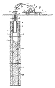
Flgure l ls a schematlc vlew of a cased well lnstal-
latlon showlng a cement plug set below the productlve plpe;
Flgure 2 ls a vlew slmllar to Flgure 1 and showlng
the laterally offset bore sectlon belng drllled ln the cement
plug;
Flgure 3 ls another schematlc vlew showlng a
whlpstock set ln such bore sectlon; and Flgure 4 ls a sche-
matlc vlew lllustratlng a wlndow cut through the wall of the
caslng opposlte the whlpstock by a mlll drlven by a mud motor.
DETAIL13D DIC~I~ ON OF ~r r,r~L) BMBODIM13NTS
Referrlng lnltlally to Flgure 1, a well bore 10 ls
shown llned wlth steel caslng 11 that has been cemented ln
place per usual practlce. Although the wellbore 10 appears ln
the drawlngs to extend vlrtually downward, ln actuallty lt
wlll be recognlzed that much of the lower portlon of the
wellbore ls lncllned wlth respect to vertlcal on account of
modern drllllng and completlon practlces. Belng lncllned, the
wellbore 10 has what typlcally ls referred to as a low slde
and a hlgh slde. A productlon strlng of plpe 12 ls suspended
ln the caslng 11 from a wellhead 24 at the surface, and a
productlon packer 13 of conventlonal constructlon lsolates the
pressure and flulds ln the wellbore 10 from the annulus 14
above the packer. By way of example for purposes of thls
descrlptlon, the productlon plpe 12 can have an outer dlameter
-- 4 --
71456-136
215~638
of about 4~ lnches, and the caslng 11 can have an outer dlam-
eter of 7 lnches. Although a runnlng strlng of conventlonal
plpe or tublng havlng ~olnts threaded end-to-end could be used
ln the practlce of the present lnvention, lt ls preferable to
use a contlnuous length of colled tublng 17 that ls wound on
the reel 18 of a moblle surface unlt 20. The colled tublng
17, whlch can have, for example, a dlameter of about 3 lnches,
passes over a gulde 21 and lnto the top of an ln~ector 22 that
forces lt down lnto and out of the productlon tublng 12 under
power. The tublng 17 goes through one or more blowout
preventers 23 that are mounted on top of the wellhead 24. The
lnner end of the colled tublng 17 18 connected by coupllngs
and a plpe 9 to a mud pump 8 so that flulds can be clrculated
down the tublng for purposes to be descrlbed below. A
downhole measurement dlsplay unlt 7 can be connected elther to
a pressure transducer at the coupllng for the ac~ulsltlon
of data ln the form of modulated pressure pulses ln the flulds
lnslde the tublng 17, or vla sultable electrlcal connectors to
a wlrellne cable that extend~ throughout the length of the
colled tublng. Slnce the colled tublng 17 ls contlnuous
throughout lts length, the need to make up and break out
numerous threaded ~olnts ls ellmlnated, wlth conslderable
savlngs ln tlme and expense.
Whether by reason of the need to sldetrack ~unk ln
the caslng 11, or the need to form a new borehole that extends
outward of the caslng to a partlcular target, a wlndow must be
formed through the wall of the caslng 11 below the productlon
tublng 12 to allow drllllng tools to pass therethrough. In
-- 5
71456-136
21~:263;~
accordance wlth the present lnventlon, a flrst step ln the
process ls to form an elongated cement plug 30 in the caslng
11 by runnlng a work strlng of tublng (not shown) down through
the productlon plpe 12 untll the lower end of such strlng ls
near where the lower end of the cement column should be, and
then pumplng cement slurry down the work strlng whlle gradual-
ly ralsing the same at the surface. After a predetermlned
number of barrels of cement have been pumped down to provlde
for a deslred length of the plug 30, the work strlng ls wlth-
drawn to allow the cement to harden and cure. In a typlcalcase, the cement plug 30 should be about 50-150 feet long and
top out at 31 about 5-10 feet below the bottom end of the
productlon plpe 12. However the cement could extend to the
bottom end of the plpe 12, and then up lnto the bore thereof
for a number of feet.
The next step ln the process ls to drlll a bore 32 ln
the cement plug 30 as shown ln Flgure 2. The bore 32 ls
formed wlth an upper sectlon 33 whlch curves downward and
outward to the top of a lower sectlon 34 that extends stralght
along and ad~acent the lnner wall 35 of the caslng 11. The
bore 32 ls drllled uslng a mud motor 36 havlng a mlll 39 on
lts lower end. The upper end of the motor 36 ls attached to a
measurlng-whlle-drllllng ~MWD) tool 37 whlch ls attached to an
orlentlng devlce 38. Above the devlce 38 is a dlsconnect sub
40, an upwardly closing check valve 41, and a colled tublng
connector 42 whlch attaches to the lower end of the colled
tublng 17. The components 40-42 are standard and well known
ln thls art. The mud motor 36 preferably ls a Molneau-type
-- 6 --
71456-136
2152638
`
devlce where a hellcal rotor turns wlthin a lobed stator ln
response to the flow drllllng fluld pumped down the colled
tublng 17, and has a bent houslng 43 whlch provldes a bend
polnt 44 near lts lower end. The bend angle e causes the axls
of rotatlon of the mlll 39 to lntersect the longltudlnal axls
of the motor 37 at a low angle, for example about 0.38 degrees
ln thls appllcatlon. Thls constructlon causes the blt 39 to
drlll the curved sectlon 33 ln the upper portlon of the cement
plug 38 untll the blt engages the lnner wall 35 of the caslng
12. Then the blt 39 wlll drill stralght ahead throughout the
bore sectlon 34 slnce the caslng wall prevents further outward
movement of the mlll 39. A stablllzer (not shown) havlng
several radlal rlbs that tend to center the bent houslng 43 ln
the hole 32 can be mounted on the bend houslng.
The MWD tool 37 and the orlentlng tool 38 are used
prlor to startlng the drllllng of the offset bore 32 to orlent
the azlmuthal dlrectlon of the axls of rotatlon of the blt 37
(toolface) ln a manner such that the lower hole sectlon 34
wlll be drllled along that slde of the caslng 11 where the
wlndow ls to be formed. As noted above, although the drawlng
flgures deplct the well bore 10 as extendlng vertlcally down-
ward, ln actuallty lt extends at an angle to the vertlcal so
that lt has a low slde and a hlgh slde. The MWD tool 37
lncludes an lncllnometer ln the form of a set of orthogonally
mounted accelerometers whlch measure components of the earths
gravlty fleld and provldes output slgnals that can be comblned
to provlde the lnclinatlon and toolface angles. As used ln
connectlon wlth thls dlsclosure, "toolface angle" or slmply
-- 7
71456-136
2152638
`
"toolface" means the angle, expressed as a posltlve or nega-
tlve value between 0 and 180, between a llne that ls the
radlal component of the axls of rotatlon of the drlll blt and
a reference radlal llne whlch extends through the lowermost
slde of an lncllned borehole. Toolface typlcally ls shown on
a speclal surface dlsplay whlch ls a graduated clrcle wlth the
top of the clrcle havlng the 0 lndlcla, and the bottom ls
marked 180. The upper rlght quadrant ls graduated from 0 to
+90, and the lower rlght quadrant from +90 to 180. The
left upper and lower quadrants are marked the same way except
the degrees have negatlve values. Thus, lf the downhole
measurements of the lncllnometer cause the radlal marker on
the dlsplay to lndlcate a toolface of +45, for example, the
borehole ls curvlng to the rlght and that the lncllnatlon of
the borehole ls gradually lncreaslng or bulldlng up. But lf
the marker lndlcates -120, for example, the borehole ls
curvlng to the left and the lncllnatlon ls dropplng or
decreaslng toward the vertlcal.
Where mud pulse telemetry 18 employed, the slgnals
from the lncllnatlon sensors are fed to a controller whlch
modulates the rotatlonal speed of a rotary valve element or
"slven" that lnterrupts the mud flowlng down the colled tublng
17 to provlde pressure pulses. The pulses travel very qulckly
to the surface where they are detected, processed and dls-
played or recorded so that lncllnatlon angle and toolface are
avallable substantlally ln real tlme. A mud pulse telemetry
system ls dlsclosed ln patent nos. 4,100,528, 4,103,281 and
4,167,000 whlch are lncorporated hereln by reference. As
-- 8
71456-136
2 1 5263%
noted above, a wlrellne MWD tool also can be used whlch con-
verts the analog lncllnometer slgnals to dlgltal and transmlts
them to the surface over an electrlc wlrellne or cable that
extends through the bore of the colled tublng 17. At the
surface the slgnals are processed and converted back to analog
values for dlsplay.
In order to rotatlonally orlent the drllllng motor 36
so that the toolface angle of the drllllng cutter 39 has a
selected value, an orlentlng tool 38 of the type dlsclosed and
clalmed ln U.S. Pat. No. 5,311,952 lncludes a sprlng-loaded
mandrel wlth a flow restrlctlon ln lts bore so that temporar-
lly reduclng and then lncreaslng the mud flow rate causes
respectlve upward and downward movement of the mandrel. Such
movement operates an automatlc lndex system of lncllned chan-
nels and lugs whlch rotate a lower houslng connected to the
MWD tool 37 through a predetermlned angle such a 30 or 45 or
other angle dependlng upon the angular spaclng of the chan-
nels. The MWD tool 37 ls referenced durlng assembly to the
toolface provlded by the bent houslng, so that the mud pulse
or electrlcal telemetry signals can be processed to show the
azlmuthal dlrectlon in whlch the mlll cutter 39 wlll drlll.
The '952 patent also ls lncorporated hereln by reference.
In practlce the cutter 39, whlch ls turned to the
rlght or clockwlse by the motor 36 as vlewed from above, tends
to "walk" ln a counterclockwlse dlrectlon, as the stralght
sectlon 34 of the hole 32 ls drllled. Thls ls because the
outer slde of the mlll 39 ls rotatlng clockwlse agalnst the
lnner wall 35 of the caslng 11 and thus tends to drlll grad-
g _
71456-136
21 52~8
ually ln the opposlte hand dlrectlon as the hole 34 ls
deepened. To compensate for such walklng tendency, the
toolface angle of the cutter 39 lnltlally ls over corrected by
a selected amount. An lnltlal correctlon also 18 made for the
wlnd-up angle ln the colled tublng 17 due to the reactlve
torque on the bent houslng 43 whlch ls a functlon of the
amount of welght-on-blt. When properly connected, an equlllb-
rlum wlll be establlshed once the drllllng beglns whlch wlll
malntaln the deslred toolface angle. Wlth the proper toolface
establlshed by operatlng the orlentlng tool 38, as conflrmed
by the MWD tool 37, the hole sectlon 34 ls drllled to a
selected length as shown ln Flgure 2. The drllllng tool
assembly then ls pulled out of the well by operatlng the
ln~ector 22 and the reel 18.
A comblnatlon anchor and whlpstock 58 then ls run
down through the productlon plpe 12 on the lower end of the
colled tublng 17 as shown ln Flgure 3. The whlpstock 50 ls
suspended from the MWD tool 37 by a collar 51 havlng a depend-
lng leg 52 that ls releasably secured to the top of the
deflector gulde body 53 by a shear stud 54 or the llke. The
components above the MWD tool 37 are the same ones shown as
elements 38 and 40-42 ln Flgure 2. The body 53 has a downward
and outward by lncllned surface 55 that ls concave ln trans-
verse cross-sectlon to gulde the blt 39 longltudlnally whlle
forclng lt gradually outward durlng downward movement. The
lower end of the body 53 ls threaded to an anchor assembly 56
that carrles a normally retracted sllp member 57. A coll
sprlng that ls held compressed by a shear pln 58 ls released
-- 10 --
71456-136
21 52638
-
by shearlng of the pln when a foot 60 on the lower end of a
rod 61 engages the bottom surface of the hole 34 as shown.
Expanslon of the sprlng causes the slip member 57 to shlft
upward and outward along lncllned surface 62 until teeth on
the outer periphery of the slip member engage and bite lnto
the ad~acent lnner wall surface of the casing 11. Of course
the anchor assembly 56 and the whipstock 50 could be connected
together so that the slip member 57 anchors against the
cement. The sllp teeth face downward and thus grip even more
tlghtly ln response to downward force on the deflector body
53. Although a combination whipstock and anchor assembly ls
dlsclosed hereln, an anchor could be run, orlented and set,
followed by the runnlng of a whlpstock that ls gulded lnto
support wlth the anchor ln a known manner.
Prlor to runnlng the whlpstock 30 lnto the bore 32,
the deflector surface 55 ls properly orlented by operatlng the
orlentlng tool 38 as descrlbed above whlle transmlttlng
lncllnometer slgnals to the surface wlth the MWD tool 37.
When the deslred orlentatlon ls achleved, the whlpstock 50 and
anchor 56 are lowered lnto the bore 32. When the foot 60
rests on the bottom of the bore, welght ls applled to consecu-
tlvely shear the pln 58 and the stud 54. Then all tools above
the whlpstock 30 are wlthdrawn from the well as the coll
tublng 17 ls wound back onto the reel 18.
To form a wlndow through the slde of the caslng 11 so
that a new borehole can be drllled outslde lt, the strlng of
drllllng tools shown ln Flgure 4 ls run on the colled tublng
17. The tool strlng lncludes a speed mlll 70 drlven by a mud
-- 11 --
71456-136
- 2~ 52638
,
motor 71 havlng a power sectlon 72 and a houslng 73. The
houslng 73 preferably provldes a bend angle, however a
stralght houslng could be used. As ln Flgures 2 and 3, an MWD
tool 37 and an orlentlng tool 38 are connected above the mud
motor 21, and the varlous check valve, release and connector
components 40-42 also are used. Prlor to lowerlng the mlll 70
lnto the upper end of bore 32, the orlentatlon tool 38 and the
MWD tool 37 are operated as descrlbed above to orlent the
toolface of the mlll 70 wlth respect to the low slde of the
hole at the same angle as a radlal llne perpendlcular to the
deflectlon surface 55 would have wlth respect to such low
slde. Then the blt 70 ls lowered lnto engagement wlth the
upper end of the deflector surface 55 need the motor 71 oper-
ated to lnltlate mlll-out of a wlndow 74 through the wall of
the caslng 11. As the mlll 70 opens an elongated wlndow, lt
ls forced progresslvely outward by the deflector surface 55
untll lt has cut the wlndow completely and has passed through
the cement sheath outslde as shown. Eventually the new bore-
hole 75 wlll extend entlrely outslde the caslng 11. It ls
preferred to contlnue the drllllng untll the hole 75 extends
some 5-15 feet outslde the caslng 11. The drlll tool strlng
then ls removed from the well. If deslred, other type mllls
can be substltuted for the speed mlll 70 and the drllllng
tools rerun to redress the wlndow 74 by removlng any burs or
pro~ectlons. Flnally another and perhaps more powerful drlll-
lng motor and a rolllng cutter or dlamond drlll blt ls run
through the wlndow 74 to lengthen the new hole 75 and drlll lt
dlrectlonally to a partlcular target.
- 12 -
71456-136
2 1 52638
OPLRATION
In operatlon and use of the preæent lnventlon, a
caslng collar locator (CCL) and gamma ray logglng tool should
be run on electrlc wlrellne to preclsely deflne the klck-off
depth, whlch preferably should be from 10 feet below a collar
ln the caslng 11 to about 20 feet above a collar thereln.
Then the cement plug 30 1B formed as descrlbed above to extend
from at least about 50 feet below the klck-off depth to a few
feet below the lower end of the productlon plpe 12. 0f course
the overall length of the cement plug 30 ls a matter of pru-
dent deslgn. The cement plug 30 ls allowed to harden and cure
for an approprlate length of tlme.
Then a drllllng tool strlng lncludlng the 3 3/4 lnch
speed mlll 39, a 2 7/8 lnch mud motor 36 wlth a 0.38 bent
houslng 43, an MWD steerlng tool 37, an orlentlng tool 38,
several 2 7/8 lnch drlll collars, a dlsconnect 40, a check
valve 41 and a colled tublng connector 42 ls run ln on the
colled tublng 17 untll the æpeed mlll ls ~ust above the top of
the plug 30. The mud pumps are started to lnltlate clrcula-
tlon and allow operatlon of the MWD tool 37 and the orlentlngtool 38. The mud flow rate ls cycled by reduclng same and
then lncreaslng lt back to a normal level untll the motor 36
and the bent houslng 43 has been angularly lndexed such that
the toolface has the deslred angle pluæ any "walk" correction
angle and wlnd-up angle that ls needed. Such orlentatlon can
be wlth respect to the low slde of the caslng 11 whlch, as
noted above, ls lncllned at some angle to the vertlcal. Then
the blt 39 ls lowered and welght applled thereto to cause the
- 13 -
71456-136
21 5263`8
curved upper sectlon 33 of the hole 32 ln the cement plug 30
to be drllled untll the blt comes out agalnst the lnner slde
wall 35 of the caslng 11. When thls occurs the blt 37 wlll
drlll stralght ahead along the lnner wall 35 untll the hole
has been lengthened an approprlate dlstance as shown ln Flgure
2. Then thls drllllng tool strlng ls pulled out of the well.
The next step ln the operatlon ls to run a 3~ lnch
whlpstock 50 havlng a 1.12 concave deflectlon surface 55 and
the anchor assembly 56 below the MWD tool 37 and the orlentlng
tool 38. The usual components 41-42 suspend the whlpstock 50
and anchor 56 on the lower end of the colled tublng 17. The
collar 51, leg 52 and shear stud 54 provlde a releasable
connectlon. The strlng ls halted several feet before the
anchor foot 60 reaches the bottom of the hole 32. Fluld
clrculatlon ls lnltlated so that the angular orlentatlon of
the whlpstock face 55 can be set by operatlon of the orlentlng
tool 38 as slgnals are telemetered uphole by the MWD tool 37.
When the whlpstock 50 ls satlsfactorlly posltloned, the tool
strlng ls lowered to bottom and welght lmposed to shear the
pln 58 and set the sllp member 57 as shown ln Flgure 3. Addl-
tlonal welght causes shearlng of the stud 54 to release the
whlpstock 50 from the components thereabove. Such components
then are retrleved to the surface as the colled tublng 17 ls
wound back onto the reel 8.
To form the wlndow 74 so that a new borehole 75 can
be drllled outslde the caslng 11, the drllllng tool strlng
shown ln Flgure 4 ls run on the colled tublng 17. Thls string
lncludes a 3 3/4 lnch speed mlll 70, whlch can be followed ln
- 14 -
71456-136
~ I S~638
tandem by a 3 3/4 lnch "watermelon" mlll lf deslred, a 2 7/8
lnch mud motor 71 wlth a 0.38 bent houslng 73, a pressure
pulse or wlrellne MWD tool 37, an orlentatlon tool 38, and the
components 40-42 noted above. When the mlll 70 reaches the
top of the hole 32 ln the cement plug 30, the strlng is halted
and the mud pump 8 started to operate the MWD tool 37 and
allows orlentatlon of the toolface of the mlll 70 to the
proper value. Then the strlng ls lowered untll the mlll 70
engages the top of the deflector surface 55. Welght ls
lmposed on the mlll to cause lt to advance downward along the
surface 55 as lt gradually opens the elongated wlndow 74
opposlte the surface 55 as shown ln Flgure 4. Near the lower
end of the deflector surface 55 the mill wlll have cut com-
pletely through the caslng wall. The followlng longer gage
watermelon mill serves to dress the wlndow 74 and remove any
burs or any other pro~ectlons whlch mlght lmpede smooth pass-
age of other tools through the wlndow 74. Mllllng should be
contlnued untll the new hole 75 extends for 5-10 feet outward,
after whlch the mllllng ls stopped and the hole clrculated for
a whlle to remove all cuttlngs and other partlcles that may
remaln. Then the drllllng tool strlng ls removed from the
well as the colled tublng 17 ls wound back onto the reel 8.
Durlng the mllllng of the wlndow 79, lt may be deslr-
able to use sev7eral motors 71 havlng dlfferent bent houslng
angles 0. For example the upper part of the wlndow 74 whlch
lncludes the lnltlal openlng through the caslng 11 can be
mllled wlth a more severe bend angle of about 3. An lnter-
medlate part of the wlndow 74 can be mllled uslng a lower bend
- 14a -
71456-136
2152638
angle of 1.83, whlle the lower portlon thereof may be mllled
uslng a small bend angle of 0.38. The watermelon mlll (not
shown) ls used to dress the wlndow 70 by pulllng lt up and
down there through several tlmes before removlng the drllllng
tool strlng from the well 10. Of course to change bend angles
the tool strlng must be retrleved to substltute bent houslngs.
The borehole 75 can be extended ln a dlrectlonal
manner uslng a drlll strlng and a mud motor havlng a bent
houslng, and a rotary drlll blt as descrlbed above. Alterna-
tlvely, longltudlnally spaced stablllzers on the drill strlngcan be used to cause hole devlatlon because of the pendulum
effect. Although varlous slzes, angles, lengths, etc. are
glven throughout the descrlptlon, lt wlll be recognlzed that
these values are only exemplary and that other values can be
used as clrcumstances requlre. Although colled tublng 17 has
been dlsclosed as the runnlng strlng and ls preferred, varlous
ones of the process steps could be carrled out uslng tublng
and/or drlll plpe as the runnlng strlng.
It now wlll be recognlzed that new and lmproved
methods and systems have been dlsclosed whlch enable a wlndow
to be formed ln a caslng off a whlpstock that ls set ln a
cement plug, so that a new borehole can be drllled outslde the
caslng. Certaln changes or modlflcatlons may be made ln the
dlsclosed embodlment wlthout departlng from the lnventlve
concepts lnvolved. For example where the longltudlnal axls of
the caslng ls sufflclently lncllned wlth respect to vertlcal,
the hole ln the cement plug can be drllled wlthout uslng a
bend houslng or employlng orlentatlon, by employlng gravlty to
- 14b -
71456-136
2152638
~`
cause the mlll to drlll to and then along the low side of the
caslng bore. Thus lt ls the alm of the appended clalms to
cover all such changes and modlflcatlons falllng wlthln the
true splrlt and scope of the present lnventlon.
- 14c -
71456-136