Note: Descriptions are shown in the official language in which they were submitted.
2152687
The invention relates to a tunnel-driving machine
comprising rotating drilling tools including at least one
support capable of being placed against the .tunnel wall or
tubbings.
A tunnel-driving machine of the initially defined kind
can be taken, for instance, from DE-A1 3114899. This known
arrangement is a tunnel-driving machine comprising a rotating
drilling head and suitable for hard rock or firm ground. The
drilling head is equipped with roller bits or picks. In
addition, an erector is provided for transfering tubbings.
This machine is clamped against the end faces of the tubbings
via abutment arms extending obliquely forwards and in the
direction towards the tunnel wall, and the advancing force for
the drilling head is absorbed by the end faces of the
tubbings.
Naturally, such an arrangement cannot always be used
without risk in case of teary rock. In particular, if drilling
tools are employed which are not arranged on a full-surface
disc but are arranged merely on rotating arms of corresponding
tools, the fact that the tunnel tube is not supported as far
as immediately to the face of work causes the region in the
immediate vicinity of the face of work to be jeopardized. With
the known arrangemenments, the region between the end faces of
the tubbings at which the abutment arms engage and the face of
work remains largely unprotected, at least sections of this
region being permanently unsecured.
- 1 -
CA 02152687 2005-04-07
The invention aims at providing a tunnel-driving machine
of the initially defined kind, with which the danger of
downfalls of backs or wall parts in the region of the face of
work or of the drilling tools is avoided even in case of teary
rock and a support is obtained as tar as immediately to the
face of work. To achieve this object, the invention
essentially consists in that a lost shield is arranged in the
region of the drilling tools so as to be displaceable in the
advance direction and that the shield is supported via
abutment arms in the advance direction on the driving machine,
on a pressing means or on the end faces of set tubbings.
The expression "lost shield" refers to a shield that is
"lost" in the tunnel when the tunnel-driving machine is
removed from the tunnel-driving site, i.e. the lost shield
remains in, its last position at the tunnel-driving site
when the tunnel-driving machine is removed from the tunnel-
driving site (the tunnel tube). Such a lost shield being
arranged to be displaceable in the advance direction
renders feasible securing of the remaining region of the
tunnel tube between the set tubbings and the face of work
by means of the displaceable lost shield, the support
and/or the introduction of force for the reaction forces of
the tunnel-driving machine, furthermore, occurring via the
end faces of set tubbings or suitable pressing means in a
known manner.
-2-
CA 02152687 2005-04-07
In a particularly simple mariner, the configuration
according to the invention is chosen such that the lost shield
comprises at least one inwardly projecting flange or stop for
the application of the abutment arms and the support on set
tubbings. The lost shield, which is displaceable in the
longitudinal direction or advance direction, is connected with
the shield part by pressing means in a non-positive manner
since it is to be displaced in the advance direction while
-2a-
21~268~
providing an appropriate support of the machine at the same
time. The pressing means, thus, is connected with the shield
part in a non-positive manner and the abutment face of the
shield part may get into abutment on the pressing means. It is
essential that the lost shield can be entrained while
simultaneously ensuring an appropriate support, for instance,
via the end faces of set tubbings, for which purpose the
abutment arms engage, for instance, at the end faces of set
tubbings in an outwardly pivotable manner between the
inwardly projecting flange or stop of the lost shield and the
end faces of the set tubbings.
In order to guarantee full security against descending
rocks, the lost shield according to an advantageous embodiment
externally embraces set tubbings by a portion of its~jacket,
wherein the lost shield between the flange or stop and its
rear end preferably has an axial length at least corresponding
to the axial length of a tubbing. Such dimensioning of the
length of the lost shield ensures the full security of the
rock in the rear region of the shield body, wherein it is
possible to move the shield further immediately upon a knock-
off and to set another tubbing in the already secured region.
The cutter wheel with such a configuration may be designed to
be open as is frequently the case, in particular, with teary
rocks. By using a lost shield, a support in this case may yet
be obtained as far as to the front edge of the drilling tool,
wherein the configuration preferably is chosen such that the
- 3 -
215268'
lost shield overlaps the drilling tools as far as to the face
of work.
In order not to affect the displaceabil.ity of the lost
shield relative to the tunnel-driving machine in any way, the
inwardly projecting flange or the stop advantageously extends
over partial circumferential regions of the lost shield,
which, in at least one rotatory position of the drilling
tools, register with free regions of the same such that, at a
standstill of the drilling tool, displacement of the lost
shield is readily feasible even beyond the front edge of the
drilling tool, if necessary. However, such a position is
important, in particular, for the safe retraction of the _
drilling tool, since it is that position in which the lost
shield is to remain on the face of work. In order to be able
to safely retract the drilling tool, it may be advantageous to
design radially external regions in a tiltable manner, wherein
larger wings capable of being tilted backwards from the face
of work may be provided. Such a design has the advantage. that
no separate precutting is required for the purpose of tilting
in the drilling tool. After having pivoted in the abutment
arms, the driving machine may readily be removed from the
tunnel tube for purposes of repair and conversion with the
shield body remaining in the tunnel tube. An alternative
embodiment provides for additional driving presses arranged on
the abutments of the abutment arms and pressed against the end
faces of the tubbings, wherefor dragging of the shield may be
omitted in this embodiment. This has the advantage that the
- 4 -
212687
safety of the teary rock is ensured by the lost shield between
the drilling head and set tubbings during the complete driving
procedure.
In the following, the invention will be explained in more
detail by way of an exemplary embodiment of a tunnel-driving
machine and its alternative embodiment schematically
illustrated in the drawing, wherein:
Fig. 1 is a side view of a tunnel-driving machine according
to the invention;
Fig. 2 is a view in the direction of arrow II of Fig. 1;
Fig. 3 is a view onto the lost shield in the direction of
arrow II, seen from a position behind the cutting tool; and
Figs. 4 and 5 are side views of an alternative embodiment
of the tunnel-driving machine according to the invention in
different working positions.
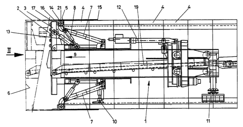
In Fig. 1 a tunnel-driving machine is denoted by 1. The
tunnel-driving machine comprises cutting tools 2 formed by
cutters fixed on rotating arms 3. In the tunnel tube tubbings
4 are set, the foremost of which tubbings has an end face 5
oriented towards the face of work 6. Abutment arms 7 are
provided, which are pivotable radially outwards by means of
hydraulic cylinder-piston aggregates 8 and can be pressed
against the end faces 5 of the tubbings 4. Adjustment of the
drilling tools 2 in the advance direction 9 may be effected by
the abutment arms 7. In addition, the tunnel-driving machine
can be stabilized within the tunnel tube by radial supports 10
as well as, if required, a rear support 11. In the
- 5 -
~1~2687
illustration according to Fig. 1, an erector arm 12 is,
furthermore, schematically shown, by which tubbings may be set
at the tunnel wall.
The arms 3 of the drilling tool may be pivoted backwards
by means of hydraulic cylinder-piston aggregates 13 in order
to move the tunnel-driving machine 1 again out of the tunnel
tube opposite to the advance direction 9.
In the region of the cutting tools 2 and of the arms 3,
respectively, a lost shield 14 is arranged, whose rear edge 15
overlaps at least one tabbing segment 4. A radially inwardly
projecting support 16 is visible, via which the lost shield 14
may be displaced in the advance direction 9 by means of the
abutment arms 7, the front end 17 of the lost shield 14
overlapping the rotating arms 3 and the drilling tools 2,
respectively.
As is apparent from the illustrations according to Figs.
2 and 3, free spaces 18 are each provided between
circumferentially neighboring arms 3 carrying the drilling
tools 2. The tabbing segments 4 are pivoted out into their
positions at the periphery of the tunnel tube via erector arms
12, as is apparent, in particular, from Fig. 3. The radially
inwardly projecting annular brim 16 of the lost shield 14 may
extend in the circumferential direction over partial regions
substantially corresponding to the central angles of the free
spaces 18 and registering with the same in a particular
rotatory position of the cutting tools. By pivoting the arms 3
backwards, the projection of the cutting tools alternatively
- 6 -
2m2ss7
may be brought to a circumference that is smaller than the
inner circumference of the flange or annular brim 16 such
that, also by such a measure, the extraction of the tunnel-
driving machine 1 is feasible even if the annular flange 16
extends over the entire circumference.
In the interior of the tunneling machine, a discharging
means 19 is schematically indicated. The erector arms 12 are
supported on part of the tunneling machine 1 so as to be
displaceable in the longitudinal direction of the tunneling
machine.
Figs. 4 and 5 represent an alternative embodiment of the
tunnel-driving machine 1, in which additional driving presses ~~,
provided on the abutments 21 of the abutment arms 7 are
pressed against the end faces 5, Fig. 4 illustrating.the
15 starting position with the driving presses retracted and Fig.
5 depicting the tunnel-driving machine after a working stroke.