Language selection

Search

Patent 2152768 Summary

Third-party information liability

Some of the information on this Web page has been provided by external sources. The Government of Canada is not responsible for the accuracy, reliability or currency of the information supplied by external sources. Users wishing to rely upon this information should consult directly with the source of the information. Content provided by external sources is not subject to official languages, privacy and accessibility requirements.

Claims and Abstract availability

Any discrepancies in the text and image of the Claims and Abstract are due to differing posting times. Text of the Claims and Abstract are posted:

  • At the time the application is open to public inspection;
  • At the time of issue of the patent (grant).
(12) Patent: (11) CA 2152768
(54) English Title: ALIGNMENT GUIDE FOR USE IN ORTHOPAEDIC SURGERY
(54) French Title: GUIDE D'ALIGNEMENT POUR CHIRURGIE ORTHOPEDIQUE
Status: Deemed expired
Bibliographic Data
(51) International Patent Classification (IPC):
  • A61B 17/90 (2006.01)
  • A61B 17/15 (2006.01)
(72) Inventors :
  • BURKE, DENNIS W. (United States of America)
  • PETERSEN, THOMAS (United States of America)
  • KRUEGER, DAVID (United States of America)
  • BAYS, RODNEY L. (United States of America)
(73) Owners :
  • BURKE, DENNIS W. (United States of America)
  • PETERSEN, THOMAS (United States of America)
  • BRISTOL-MYERS SQUIBB COMPANY (United States of America)
(71) Applicants :
  • BURKE, DENNIS W. (United States of America)
  • PETERSEN, THOMAS (United States of America)
  • BRISTOL-MYERS SQUIBB COMPANY (United States of America)
(74) Agent: GOWLING WLG (CANADA) LLP
(74) Associate agent:
(45) Issued: 2005-08-30
(22) Filed Date: 1995-06-27
(41) Open to Public Inspection: 1995-12-28
Examination requested: 2002-06-13
Availability of licence: N/A
(25) Language of filing: English

Patent Cooperation Treaty (PCT): No

(30) Application Priority Data:
Application No. Country/Territory Date
08/265,884 United States of America 1994-06-27

Abstracts

English Abstract

The alignment guide of this invention includes a cam rotatable about the longitudinal axis of the alignment guide as defined by an intramedullary rod. A base plate is pivotally connected to the intramedullary rod and includes a pair of cam followers positioned on opposite sides of the intramedullary rod. In use, as the cam is rotated relative to the rod, the cam followers ride against the cam causing the plate to pivot or angulate relative to the rod. A plurality of indicia are formed on the cam to indicate to the surgeon the relative angle between the plate and the rod. The base plate includes a quick connect mechanism to permit the surgeon to quickly attach a device such as a cutting guide or pinning guide to the base plate. The cutting guide is fixed relative to the base plate such that the cutting guide will be at the same angular orientation as the plate relative to the intramedullary rod.


French Abstract

Le guide d'alignement de cette invention comprend une came rotative autour de l'axe longitudinal du guide d'alignement tel que défini par une tige intramédullaire. Une plaque de base est raccordée en pivot à la tige intramédullaire et comprend deux galets sur les côtés opposés de la tige intramédullaire. En utilisation, comme la came pivote autour de la tige, les galets se déplacent contre la came et font ainsi pivoter ou former un angle par rapport à la plaque par rapport à la tige. Une pluralité d'indices est formée sur la came pour indiquer au chirurgien l'angle relatif entre la plaque et la tige. La plaque de base comprend un mécanisme de fixation rapide permettant au chirurgien de fixer rapidement un périphérique tel qu'un guide de coupe ou un guide de tige à la plaque de base. Le guide de coupe est fixe par rapport à la plaque de base de manière à ce que le guide de coupe soit orienté en angle de la même manière que la plaque par rapport à la tige intramédullaire.

Claims

Note: Claims are shown in the official language in which they were submitted.


-6-

WE CLAIM:

1. An alignment guide for an orthopaedic instrument,
the alignment guide including an intramedullary rod, a base
plate pivotally connected adjacent one end of the rod, and
a cam means carried by the rod in engagement with the base
plate for orienting the base plate at an angle relative to
the rod.
2. The alignment guide of Claim 1 wherein the cam
means includes a generally cylindrical cam rotationally
positioned about the rod, the cam including a camming face,
the plate having at least one cam follower in contact with
the camming face.
3. The alignment guide of Claim 2 wherein the
cylindrical cam includes a central through bore for
accommodating a portion of the rod and lies in a plane
generally transverse to the rod.
4. The alignment guide of Claim 1 further including
indicia on an exterior periphery of the cam means for
indicating the relative angle between the rod and the base
plate.
5. The alignment guide of Claim 1 further including
a coupling means carried by the base plate for connecting
a device to the base plate, said coupling means including
a latch mechanism which is positionable in a first position
wherein a portion of the latch extends into the device and
a second position wherein the portion of the latch is
spaced from the device.
6. The alignment guide of Claim 5 wherein the
coupling means is positioned eccentric to the base plate
such that in the first position one end of the coupling
means extends beyond a periphery of the base plate and in
a second position the one end of the coupling means is
positioned interior of the periphery of the base plate.
7. A resection guide for use in orthopaedic surgery
to guide a cutting device for resection of a portion of a
patient's bone to accommodate an orthopaedic implant, the
guide including an intramedullary rod configured for


-7-

insertion into an intramedullary canal of a patient's bone,
a base pivotally connected to the rod and lying in a plane
generally transverse to the rod, a cam carried by the rod
and rotatable relative thereto, the base having at least
one cam follower in engagement with the cam, wherein as the
cam is rotated about the rod, the relative angle between
the rod and the base is varied, and a resection guide
connected to the base for guiding a resection instrument.

Description

Note: Descriptions are shown in the official language in which they were submitted.


~i~~~68
ZM-0255 ALIGNMENT GUIDE FOR USE IN ORTHOPAEDIC
SURGERY
Field of the Invention
This invention relates to orthopaedic instruments and
has specific relevance to an intramedullary alignment guide
having a rotatable cam means to provide angular adjustment
between the intramedullary rod and a reference plate
carried by the guide.
Background of the Invention
In joint replacement surgery the surgeon may be
required to make several cuts through the bone to prepare
the patient's bones for the prosthetic knee implant. Over
the years, a multitude of instruments have been developed
to assist the surgeon in accurately aligning the various
cuts with reference to the anatomical axes of the patient's
joint. Many of these devices are adjustable to permit the
surgeon to position the instrument at an appropriate angle.
Summary of the Invention
The alignment guide of this invention includes a cam
rotatable about the longitudinal axis of the alignment
guide as defined by an intramedullary rod. A base plate is
pivotally connected to the intramedullary rod and includes
a pair of cam followers positioned on opposite sides of the
intramedullary rod. In use, as the cam is rotated relative
to the rod, the cam followers ride against the cam causing
the plate to pivot or angulate relative to the rod. A
plurality of indicia are formed on the cam to indicate to
the surgeon the relative angle between the plate and the
rod. The base plate includes a quick connect mechanism to
permit the surgeon to quickly attach a device such as a
cutting guide or pinning guide to the base plate. The
cutting guide is fixed relative to the base plate such that
the cutting guide will be at the same angular orientation
as the plate relative to the intramedullary rod.


-2-
Accordingly, it is an object of the invention to
provide for a novel alignment guide for orthopaedic surgery.
Another object of the invention is to provide for a
novel adjustment mechanism for an alignment guide for use
in orthopaedic surgery.
Still another object of the invention is to provide
for a novel locking mechanism for attaching a cutting head
to an alignment guide.
Still other objects of the invention will become
apparent upon a reading of the following description taken
with the accompanying drawings.
Brief Description of the Drawings
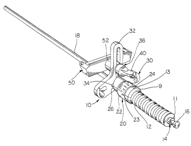
Fig. 1 is a perspective view of the alignment guide of
this invention.
Fig. 2 is a side elevational view of the alignment
guide of the invention.
Fig. 3 is a sectional view taken along lines 3-3 of
Fig. 2.
Fig. 4 a side elevational view of the alignment guide
of the invention with the cam fully rotated.
Fig. 5 is a top elevational view of Fig. 4.
Fig. 6 is a sectional view taken along lines 6-6 of
Fig. 2.
Fig. 7 is an enlarged view of the quick connect
mechanism with portions sectioned for illustrative
purposes.
Description of the Preferred Embodiment
The preferred embodiment herein described is not
intended to be exhaustive or to limit the invention to the
precise form disclosed. Rather, it is chosen and described
to best explain the invention so that others skilled in the
art might utilize its teachings.
Referring now to the drawings, alignment guide 10
includes a handle 12 which includes a plurality of annular
grooves to provide a roughened surface for gripping by the


21~~'~6
-3-
surgeon. Handle 12 includes a central longitudinal bore
which accommodates a portion of intramedullary rod 14. Rod
14 is secured relative to the handle by a pin or screw (not
shown) or other suitable means. A small portion 16 of rod
14 extends outwardly of end 11 handle 12 and forms a means
for attaching a known extracting instrument to the guide.
A larger portion 18 of rod 14 extends from end 9 of handle
12 and is configured to extend into an intramedullary canal
of a bone during a joint replacement surgery.
A cam 20 is carried by rod 14 adjacent handle end 9
and is rotatable about the rod relative to handle 12. Cam
includes a generally cylindrical body 22 having a first
end 24 which is generally perpendicular to the periphery of
body 22. End 24 is positioned adjacent end 9 of handle 12.
15 Cam 20 includes a second end 26 which is positioned at an
angle as illustrated relative to the end 24 of body 22.
Cam 20 is therefore generally wedge shaped with the second
end 26 forming the Gaming surface for cam 20. A plurality
of indicia 23 are formed on body 22 and when aligned with
20 a notch 13 of handle 12 provides an indication to the
surgeon of the relative angle between rod 18 and base plate
30. A pair of spring biased plungers 25 (see Fig. 3) are
carried within blind bores formed in cam body 22 and engage
small detents (not shown) within handle 12 on a mating
surface of end 9 to provide a series of positive stop
positions for the cam relative to the handle as the cam is
rotated.
A base plate 30, shaped as illustrated, is connected
to intramedullary rod 14 by a pin (not shown) and is
pivotal about the pin relative to rod 14. A pair of
protrusions or cam followers 34 extend from plate 30 toward
cam 20 and contact the second surface 26 of the cam. Cam
followers 34 are positioned on opposite sides of rod 14.
Plate 30 may include openings for accommodating other
instruments such as spacer buttons or plates for offsetting
the alignment guide from the bone. A tower 32 extends from
base plate 30 and is co-planer with the plate. Tower 32


21~2,~~~
-4-
includes a longitudinal slot as shown. A coupling device
36 is shiftably carried by tower 32 and is positioned
within the slot.
Coupling device 36 (illustrated best in Fig. 7)
includes a generally ovoid latch 38 having a rod 39 coupled
to one end thereof. A finger actuated knob 40 is connected
to the opposite end of rod 39. Rod 39 extends through the
slot in tower 32 and through base 41. Base 41 as
illustrated includes a generally V-shaped recessed area 42
which accommodates latch 38 and defines its rotational
limits. Rod 39 passes through base 41 off center such that
the tip of latch 38 extends beyond the side periphery of
base 41 when the latch is rotated into the position of Fig.
6. When latch 38 is rotated by rod 39 into the position
shown in phantom lines in Fig. 6, the tip of the latch lays
interior to the side periphery of the base. Coupling
device 36 further includes a compression spring (not shown)
extending between knob 40 and base 41 to frictionally hold
the coupling device to the tower.
The cutting guide 50 includes a body having a slot
therethrough for accommodating a surgical saw blade. Guide
50 further includes a hollow cylindrical protrusion 52
which includes an annular grove 54 formed therein. In use,
guide 50 is connected to tower 32 by coupling device 36.
Cylindrical protrusion 52 is placed over base 40 and latch
38 is rotated into the position illustrated in Fig. 6
wherein the tip of the latch extends beyond the side
periphery of the base and into annular grove 54 of the
protrusion. To unlock the guide 50, latch 38 is rotated by
rod 39 so as to be positioned as shown in phantom lines in
Fig. 6 out of annular groove 54. Guide 50 may be slid off
of coupling device 36.
To angulate base 30 relative to rod 18, the surgeon
rotates cam 20 relative to the rod. Cam followers 34 in
contact with camming surface 26 of cam 20 cause base 30 to
rotate about its pivot pin (not shown) to position the
plate at an angle relative to the rod. The indicia


21~2~6~
-5-
provided on the cam indicates the relative angle to the
surgeon. It should be understood that the cutting device
50, or any other device, connected to the plate will also
be positioned at the same angle relative to the rod.
It should also be understood that although a cutting
guide is illustrated, any number of instruments could be
attached to the plate using the coupling mechanism so the
device includes a cylinder with an internal groove as
described above.
Finally, it should be understood that the invention is
not to be limited to specific details above but may be
altered within the scope of the amended claims.

Representative Drawing
A single figure which represents the drawing illustrating the invention.
Administrative Status

For a clearer understanding of the status of the application/patent presented on this page, the site Disclaimer , as well as the definitions for Patent , Administrative Status , Maintenance Fee  and Payment History  should be consulted.

Administrative Status

Title Date
Forecasted Issue Date 2005-08-30
(22) Filed 1995-06-27
(41) Open to Public Inspection 1995-12-28
Examination Requested 2002-06-13
(45) Issued 2005-08-30
Deemed Expired 2015-06-29

Abandonment History

There is no abandonment history.

Payment History

Fee Type Anniversary Year Due Date Amount Paid Paid Date
Application Fee $0.00 1995-06-27
Registration of a document - section 124 $0.00 1996-02-22
Maintenance Fee - Application - New Act 2 1997-06-27 $100.00 1997-05-27
Maintenance Fee - Application - New Act 3 1998-06-29 $100.00 1998-05-15
Maintenance Fee - Application - New Act 4 1999-06-28 $100.00 1999-05-18
Maintenance Fee - Application - New Act 5 2000-06-27 $150.00 2000-05-25
Maintenance Fee - Application - New Act 6 2001-06-27 $150.00 2001-06-06
Maintenance Fee - Application - New Act 7 2002-06-27 $150.00 2002-06-03
Request for Examination $400.00 2002-06-13
Maintenance Fee - Application - New Act 8 2003-06-27 $150.00 2003-06-03
Maintenance Fee - Application - New Act 9 2004-06-28 $200.00 2004-06-15
Maintenance Fee - Application - New Act 10 2005-06-27 $250.00 2005-06-08
Final Fee $300.00 2005-06-17
Maintenance Fee - Patent - New Act 11 2006-06-27 $250.00 2006-05-30
Maintenance Fee - Patent - New Act 12 2007-06-27 $250.00 2007-05-30
Maintenance Fee - Patent - New Act 13 2008-06-27 $250.00 2008-05-30
Maintenance Fee - Patent - New Act 14 2009-06-29 $250.00 2009-06-01
Maintenance Fee - Patent - New Act 15 2010-06-28 $450.00 2010-05-07
Maintenance Fee - Patent - New Act 16 2011-06-27 $450.00 2011-05-18
Maintenance Fee - Patent - New Act 17 2012-06-27 $450.00 2012-05-24
Maintenance Fee - Patent - New Act 18 2013-06-27 $450.00 2013-05-08
Owners on Record

Note: Records showing the ownership history in alphabetical order.

Current Owners on Record
BURKE, DENNIS W.
PETERSEN, THOMAS
BRISTOL-MYERS SQUIBB COMPANY
Past Owners on Record
BAYS, RODNEY L.
KRUEGER, DAVID
Past Owners that do not appear in the "Owners on Record" listing will appear in other documentation within the application.
Documents

To view selected files, please enter reCAPTCHA code :


To view images, click a link in the Document Description column. To download the documents, select one or more checkboxes in the first column and then click the "Download Selected in PDF format (Zip Archive)" or the "Download Selected as Single PDF" button.

List of published and non-published patent-specific documents on the CPD .

If you have any difficulty accessing content, you can call the Client Service Centre at 1-866-997-1936 or send them an e-mail at CIPO Client Service Centre.


Document
Description 
Date
(yyyy-mm-dd) 
Number of pages   Size of Image (KB) 
Representative Drawing 1998-08-21 1 21
Cover Page 1995-06-27 1 19
Abstract 1995-06-27 1 26
Description 1995-06-27 5 209
Claims 1995-06-27 2 61
Drawings 1995-06-27 4 88
Representative Drawing 2005-04-27 1 12
Cover Page 2005-08-09 1 47
Assignment 1995-06-27 9 384
Prosecution-Amendment 2002-06-13 1 46
Correspondence 2002-07-26 3 140
Correspondence 2002-10-30 3 159
Correspondence 2005-06-17 1 35