Note: Descriptions are shown in the official language in which they were submitted.
~ WO94/21890 21 5 2 ~ 0 ~ PCT~S94102557
YIELDABLE CONFINED CORE MINE ROOF SUPPORT
I. BACKGROUND OF INVENTION
A. The Field of the Invention
This invention relates to the field of
devices used to provide roof and floor support in
underground mines, especially coal mines. The
invention is particularly useful for areas which
require substantial roof support and which may be in
danger of roof cave-in, including areas where roof
support by wood cribbing has typically been used. The
invention also helps prevent and minimize floor heave
o~ buckling of a mine floor. The primary application
of the invention is expected to be in longwall mining.
The invention also has application in any underground
mine where common wood cribbing or other methods are
presently used to support the mine roof. The invention
is particularly useful in preventing, delaying, and/or
controlling both mine roof collapse and mine floor
heave, reducing underground mine fire danger, and
facilitating air and traffic flow within a mine.
B. The Background Art
Various roof support devices in the prior
art have been designed and used to provide support to
the mine roof. Deep mining results in removal of
WO94/21890 PCT~S94/02557 ~
21S28~2
material from the interior of a mine, leaving
unsupported voids of various sizes within the mine
which may be in danger of col~apsing. It is desirable
to provide support to the mine roof to prevent, delay,
or control collapse. Further, it is desirable for the
mine roof support to be such that travel within the
mine is not unduly restricted, that air flow within the
mine re~; n.C adequate to support human life and to
remove exhaust gases of various mach;nery in use in the
mine, and that the danger of fire within the mine is
not increased.
One possible method of mine roof support is
to leave internal pillars of rock, coal, ore or other
material to support the mine roof. The pillars are
material which would normally be removed from the mine
but for the need to support the mine roof. This method
for supporting a mine roof is undesirable because the
material which must be left in the mine to form the
supportive pillars is usually coal or ore and
represents substantial economic value to the mine
owner. Further, no support is found for the mine roof
between pillars and there may still be substantial
danger of mine roof collapse.
Wooden beams or timbers have also been used
in the past to provide mine roof support. Wooden beams
have a serious safety disadvantage in their inability
~ WO94121890 215 2 8 0 2 PCT~S94/02557
to yield and absorb load from the mine roof. Instead,
they have a tendency to unexpectedly snap under load
giving way to a mine roof collapse. Wooden beams are
also subject to weakening over time due to
decomposition, drying, cracking and splitting. The
fire danger within a mine is increased with the
presence of wooden beams. Wooden beams supported with
wooden posts are also susceptible to the problems
stated above.
Wooden posts have been tried as mine roof
supports, with varying degrees of success. Single and
multiple (ganged) wooden posts, of various diameters
may be cut to fit between the mine roof and floor. The
posts are held tight with wooden wedges and header
boards at the top and/or bottom of the posts. These
wooden posts are susceptible to the problems listed
above and to catastrophic buckling.
The closest prior art to the present
invention in current use in the mining industry today
is wood cribbing. Traditional wood cribbing typically
uses overlapping layers of two or more rectangular wood
blocks stacked on each other in alternating fashion
from the mine floor to the mine roof to form a roof
support which is square in cross section and generally
open in the center. The wood blocks may be of various
sizes, including standard 8" x 8" x 48". The
W O 94/21890 PCTrUS94102557
21528~2 ~
advantage of standard wood cribbing over other prior
art mine roof supports is its combination of yield
range, load support capacity, and stability. Wood
cribbing will typically support a mine roof and yield
to the compressive force of the mine roof over a wider
range than many other alternative prior art mine roof
supports. Traditional wood cribbing may continue to
prove some roof support when it i8 crushed up to
approximately 40~ of its initial height. As it
compresses, wood cribbing has been found to experience
an increase in load carrying capacity of up to 400~.
Both of these are desirable characteristics in a mine
roof support. Typically, wood cribbing structure will
buckle when crushed from 20~ to 40~ of its initial
height, if the height to width ratio is less than two.
This results in total loss of support characteristics
and can lead to roof collapse and floor heave.
Wood cribbing has been more predictable than
many other types of prior art mine roof supports, being
less likely to collapse unexpectedly. Wood cribbing,
however is subject to weakening over time due to
decomposition, drying and cracking or splitting, it
requires the use of expensive and sometimes difficult
to obtain wood products, it must be assembled from
multiple pieces of wood within the mine using costly
human labor, and it will burn during a mine fire.
~ WO94/21890 21 S 2 8 0 2 PCT~S94102557
Further, the shape and size of traditional wood
cribbing cause some undesirable restriction to both
traffic and air flow within the mine. Wood may be
replaced by material such as autoclaved aerated
concrete and steel mesh to achieve more long-term
durability and fire resistance, but the other problems
associated with traditional wood cribbing remain and
the cost and difficulty of installation are increased.
Variations of traditional wood cribbing
include donut and disk cribbing which comprise multiple
donut or disk-shaped members stacked from mine floor to
mine roof. Examples of this are Chlumecky (U.S. Patent
Nos. 4,565,469 and 4,497,597) and Deul tU.S. Patent No.
5,143,484). The stacked donuts or disks are typically
made of steel reinforced concrete although it would be
possible to construct them from wood or other
materials. Concrete donuts or disks do not deteriorate
as quickly as wood and will not burn, but they are
subject to cracking and crumbling because they are only
yieldable over a limited load range. Further, the
disks or donuts are heavy and require substantial hl7m;7n
labor to install. Donut or disk cribbing has the
advantage, however, of more readily facilitating
traffic within the mine than traditional wood cribbing
and providing less resistance to air flow.
--5--
WO94/21890 21~ 2~ 0 2 PCT~S94/02557 ~
An alternative method of cribbing uses
telescoping pipe with a material within the pipe to
provide yieldable resistance against pressure from the
mine roof. An example ~ ~his is Thom (U.S. Patent No.
4,712,947). As pressure from the mine roof increases,
a beam, pole or pipe telescopes within another pipe as
the material within the pipe is compressed to absorb
load. This type of mine roof support is costly to use
in large numbers because of the various custom metal
parts which must be employed. This type of mine roof
support is also subject to unexpected and severe
buckling and collapse when it is stressed beyond the
limits of its load range. Further, if wood is employed
as a component, there is no reduction in fire danger
within the mine.
II. SUMMARY OF THE INVENTION
It is an object of the invention to provide a
mine roof support for use in underground mines where
the mine roof may be in danger of roof cave-in. The
invention is designed to provide support to the mine
roof to prevent, delay, or control collapse and to
eliminate or minimize mine floor heave or buckling.
The primary function of the invention is to provide
yieldable support under a load between a mine roof and
a mine floor, whether the load is caused by a
~ WO94/21890 215 2 8 0 2 PCT~S94/02557
descending (or collapsing) mine roof or an ascending
mine floor (such as due to floor heave or buckling).
In this way, the invention impedes a decrease in the
distance between mine roof and mine floor. The
invention eliminates prior art problems of insufficient
load holding capacity, inadequate support capacity
versus yield variability, and inade~uate load range
before failure. To achieve these purposes, the
invention will yield and absorb load from the mine roof
with no tendency to unexpectedly snap under load giving
way to a mine roof collapse. Buckling, crushing,
breaking and block rolling are also eliminated or
minimized. As load on the invention is increased and
the invention yields under the load, there is an
increase in the load carrying capacity of the invention
due to the increasing density of the material
comprising the invention as it yields. This results in
a wide load range which the invention can accommodate
while maintaining yield ability. Both the load range
and the yield range of the invention are substantially
greater than that of prior art mine roof supports.
The invention eliminates unexpected and severe buckling
and collapse when stressed beyond the limits of its
load range, because it simply yields further upon
itself, still providing roof support rather than
buckling and falling away. This provides a predictable
W094/21890 215 2 8 ~ 2 PCT~S94/02557
mine roof support because personnel working within the
mine can visually observe the amount of yield of the
invention, and hence the load applied to it and the
likelihood that it may soon fail~
Another object of ~e invention is to provide
a mine roof support which has the structural strength
required to support the mine roof without punching a
hole in the mine roof and/or mine floor. Many prior
art mine roof supports which had ample structural
strength failed due to punching a hole in the mine roof
and/or mine floor. The invention yields under load so
that excessive pressure on the mine roof and floor and
the resulting punching are eliminated.
Another object of the invention is to provide
a mine roof support which is not subject to weakening
over time. The invention eliminates the use of
materials which are subject to decomposition, drying
and cracking or splitting and hence weakening over time
as found in some prior art mine roof supports.
Another object of the invention is to provide
a mine roof support which m; n; m; zes restriction of
travel and restriction of access within the mine. The
invention occupies m;n;m~l space within the mine, far
less than traditional wood cribbing, and provides
little impedance to traffic within the mine.
~ WO94/21890 PCT~S94/02557
21~2802
Another object of the invention is to provide
a mine roof support which minimizes restriction of air
flow within the mine, so that air flow remains adequate
to support human life and to remove exhaust gases of
various machinery in use in the mine. The preferred
embodiment of the invention provides a mine roof
support which has a rounded exterior surface, the least
restrictive shape for accommodating air movement from
any direction.
Another object of the invention is to provide
a mine roof support which reduces the danger of fire
within the mine. The preferred embodiment of the
invention provides a mine roof support which
substantially reduces fire danger compared to prior art
mine roof supports.
Another object of the invention is to provide
a mine roof support which is economical to manufacture
and install, omitting custom-made components, multiple
pieces, heavy articles, or costly materials, utilizing
readily-available standard components, and not
requiring substantial human labor to manufacture or
install. Installation time is reduced due to the
simplicity of the design of the invention. This
results in a mine roof support which has a lower cost
per unit of load supported and a lower overall cost per
mine than prior art mine roof supports. A related
WO94/21890 PCT~S94/02557
21~2802 ~
advantage of the invention is increased safety for mine
personnel due to elimination of most manual aspects of
installation. ~s~
Another object of the invention is to reduce
mine floor heave or buckling.
Further objects and advantages of the
invention will become apparent to those skilled in the
art.
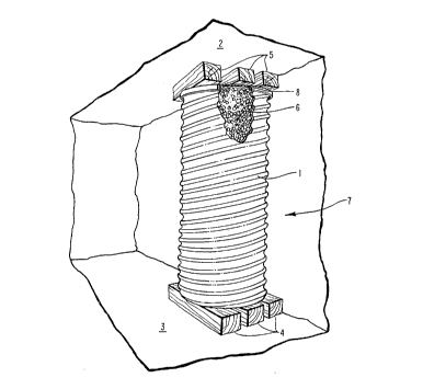
III. BRIEF DESCRIPTION OF THE DRAWINGS
Figure l depicts a cut-away perspective view
of one preferred embodiment of the invention in use
within an underground mine.
Figure 2 depicts one preferred embodiment of
the invention yielding under load from a mine roof.
IV. DETAILED DESCRIPTION OF THE PREFERRED EMBODIMENT
The invention is called a "yieldable confined
core mine roof support" although it provides yieldable
support to both a mine roof and to a mine floor. It
comprises a compressible or crushable filler within a
yieldable confining structure. Referring to Figure l,
a cut-away perspective view of one preferred embodiment
of the 1nvention in use in an underground mine is
depicted. Shown are the roof support 7, positioned
longitudinally between the mine roof 2 and the mine
--10--
WO94/21890 ~ ~ 2 8 0 2 PCT~S94/02557
floor 3. Footing material 4 and 5 is shown beneath and
above the roof support 7, respectively, and can be used
for levelling uneven mine surfaces for placement of the
roof support 7 and for filling a void above a roof
support 7. The footing material depicted in Figure l
is traditional wood cribbing, although many materials,
including natural or man-made blocks, wedges, plates,
donuts or other shapes would suffice. Foam injection
may also be used to fill the void from the top of the
container l to the mine roof 2. The footing material 4
is considered a means for levelling a roof support with
a mine floor and the footing material 5 is considered a
means for filling a void above a roof support 7.
The roof support 7 comprises a confining
structure or container l surrounding a filler 6. The
container l is considered means for surrounding,
holding, confining or containing a filler. The
container l is adapted to be placed with its
longitl~; n~l axis in substantially a vertical
orientation between a mine floor and a mine roof. The
container 7 would be considered to have its
longitudinal axis in substantially a vertical
orientation if it were perfectly vertical or angled up
to 25 degrees or more to vertical. In some preferred
embodiments of the invention, end caps 8 may be placed
at either end of the container l to prevent escape of
--11-- ,
-
WO94/21890 2 ~ ~ 2 8 ~ ~ PCT~S94/02557 ~
the filler 6. In one preferred embodiment of the
invention, 0.25" steel plate is used for end cap
material. In another preferred emb~odiment, 14 gauge
steel is used for the end cap. Various other
thicknesses of steel, other metals including aluminum,
and other materials including wood, concrete,
fiberglass, plastic, composite materials or others
would be suitable for end caps and could perform
equally well if configured to prevent escape of filler
6 from the container l. End caps 8 are considered
means for preventing escape of filler 6 from the
container l. The container l serves to at all times
contain the filler 6. The combination of container l
and filler 6 are yieldable to absorb and sustain load
from the mine roof 2, and to prevent excessive pressure
from being exerted on the mine roof 2 or mine floor 3
and thereby avoid punching. Yieldability and
support characteristics of the roof support 7 also
reduce or eliminate mine floor heave or buckling.
Referring to Figure 2, one preferred
embodiment of the invention yielding under an axial
load exerted by a descending mine roof or an ascending
mine floor is depicted. The invention is expected to
provide the same performance characteristics whether
the load on the roof support 7 is from a descending
mine roof (such as potential roof collapse~ or from an
-12-
WO94/21890 PCT~S94/02557
~ 21~;28Q2
ascending mine floor (such as floor heave or buckling).
The container 1 has been partially compressed or folded
down upon itself as it yielded and as the filler 6 was
compressed in response to axial load from the mine roof
2. The entire invention yielded upon itself under a
substantially axial load (i.e. load along the
longitudinal axis of the invention, oriented vertically
between mine floor and mine roof), and in so yielding,
the combination of said container and said filler
within said container provide continued yieldable
support to said roof and impede its descent toward the
mine floor. The invention provides the desired
performance characteristics under any substantially
axial load, a substantially axial load being any load
along the axis of the container 1 or any load oriented
up to 45 degrees from the axis of the container 1. An
increase in load-carrying ability of the invention
corresponds to such a yielding by the invention due to
the increase in density of the filler 6 as it is
compressed. An increase in load-carrying ability of
several hundred percent due to yielding is typical.
Although axial load on the invention beyond its load
range will result in substantial crushing and an
eventual decrease in load-carrying ability, rigorous
laboratory and field testing have been unable to cause
complete failure of the invention in any instance.
WO94/21890 2 ~ ~ Z 8 ~ 2 PCT~S94/02557 ~
In a preferred embodiment, the invention
yields upon itself in an accordion-like fashion under
load. The combination of conta1ner l and filler 6
provides an invention which can accommodate a wide load
range while maintaining yield ability, continuing to
provide support to a mine roof even after yielding a
substantial portion of its initial height and reducing
risk of catastrophic failure. A further benefit is
that the yieldability of the invention serves to
minimize mine floor heave, buckling or punching which
might otherwise occur wi~h less yieldable roof
supports.
In one preferred embodiment, the container l
is made from cylindrical corrugated metal pipe which
serves to provide a confining structure about the
filler 6. Helical corrugation, as illustrated in
Figure l, is used in one preferred embodiment of the
invention. Annular corrugation, as illustrated in
Figure 2, is used in another preferred embodiment of
the invention. If corrugated materials are selected
for the container l, then any corrugated material with
sufficient strength, yield abilities, and proper
dimensional characteristics could be used as the
container l. Because the container l serves as a
confining structure, it must support the enclosed
filler 6 and yield down upon itself under axial
~ WO94/21890 21~ 2 8 0 2 PCT~S94/02557
loading, similar to the compression of an accordion,
without buckling or otherwise bending in an outward
direction which would lead to roof support failure.
Further, the container l must adequately contain the
filler 6 when yielding under load. A container l which
is subject to perforation, splitting or tearing thereby
permitting escape of filler 6 would be considered
nferlor.
In alternative preferred embodiments, the
container l may be made from material which is not
corrugated. Any straight pipe which exhibits a
tendency to yield upon itself under axial load rather
than buckling could be used for the container l. The
container l need not necessarily be cylindrical either.
A container of any shape with performance
characteristics similar to those described above would
be suitable. For example, the container l could be
octagonal, hexagonal, pentagonal, square, triangular,
spherical or otherwise. Alternatively, a container
which i8 cylindrical and is corrugated along its
longitudinal axis may also possess the desired
performance characteristics.
The container l could also be constructed
from wire mesh, a net-like structure, chain-link
material, a lattice structure, or even stacks of new,
blemished, or used tires if the desired performance
WO94/21890 PCT~S94/02557
~ 21S28~2
characteristics are achieved. Another possible
construction of the container would use composite or
laminated materials, such as graphite or fiberglass
composite employing a resin. This configuration would
provide a lightweight container with substantial side,
hoop or burst strength. In the preferred embodiment,
cylindrical helically corrugated metal pipe provides
optimum mine roof performance characteristics for the
container while having the advantages of being non-
flammable, providing less impedance to traffic within
the mine, and providing less ventilation resistance
than prior art wood cribbing. Experimental test
results show corrugated metal pipe to be a suitable
container. Further, corrugated metal pipe is a very
inexpensive material commonly available and need not be
custom manufactured, making the preferred embodiment of
the invention an economical alternative to prior art
mine roof supports.
Several types of containers have been tested
successfully. Typically, 16 gauge, 14 gauge, 12 gauge,
and 10 gauge helical and annular corrugated pipe which
yields upon itself in an accordion-like fashion under
axial load is preferred. Pipes with an inside and
outside diameter of 42" and 48" have been found to be
acceptable although others could be substituted.
Depending on the type of mine, the type of mining
-16-
~ WO94/21890 21~ 2 8 ~ 2 PCT~S94/02557
equipment used, and the load support desired,
containers could vary in diameter from less than 6
inches to more than 72 inches, and the thickness of the
container wall could vary from less than 20 gauge to
more than one-half inch thick. In one preferred
embodiment, the container used is of 16 gauge steel and
is 48" in diameter, for use in a mine with a nine foot
high roof. In another preferred embodiment, the
container used is 16 gauge steel and is 42" in diameter
for use in a mine with a seven and a half foot high
roof. Various other dimensions are possible for mine
roofs which may range from less than 30" to more than
15 feet in height. Performance characteristics, cost
and weight are expected to be the critical factors for
selecting a container. Many containers or confining
structures for filler 6 which is compressible under
axial load could be acceptable for the container 1. In
some preferred embodiments of the invention, the top
and bottom of the container 1 are covered to prevent
escape of filler 6 under load and loss of support
characteristics. End caps 8 may be utilized for this
purpose. For example, 1/4" steel plate could be welded
to or placed on the ends of container 1 as end caps 8.
Wooden boards could be placed across the ends of the
container 1, concrete disk cribbing could be placed
over the ends of the container 1 or steel plate disks
-17-
WO94t21890 PCT~S94/02557
2~S28~2
crimped over flanged end of container 1.
Alternatively, concrete or steel disks could be placed
inside with the ends of container l folded or crimped
over the disks, or any other matèrial or structure and
attachment methods could be utilized as end caps 8 if
the strength characteristics are adequate for
preventing escape of filler 6 under load and during
yield. In general, the preferred embodiment of the
invention unitizes a container l which omits rivets
which may break or pull through the container wall
under stress. In some embodiments of the invention,
however, rivets and/or container wall thickness and/or
strength which resist pulling through the container
wall under stress could be utilized. Similarly, any
seams on the container 1 should exhibit sufficient
strength to avoid rupture throughout the desired load
and yield range.
When the roof support 7 is in use, a
compressible or crushable filler 6 is found within the
container 1. The filler 6 used in one preferred
embodiment of the invention is minus three inch
volcanic pumice. Other sizes of volcanic pumice can be
used in other embodiments of the invention. Any
material with the proper strength and compression or
crushing characteristics to support the mine roof and
mine floor while being subject to a wide load range
-18-
WO94/21890 215 2 8 0~ PCT~S94/02557
could be used. The filler 6 should also avoid creating
- significant side or hoop stress under load. Some
examples of other fillers known to be effective in
varying degrees are chemical foams, cementitious foams,
tires, coal and volcanic cinders. Other materials
which may be used as fillers include fly ash, cinders,
slag, limestone, gypsum, light and heavy aggrçgate,
peralite, utelite, wood, rubber and others.
Combinations of these and other materials could also be
used to produce a filler with the density and
compressibility desired. In the preferred embodiment,
minus three inch volcanic pumice is used due its load
range, compressibility, non-flammability, low cost,
long-term durability, relatively light weight and
availability.
In an alternative embodiment of the
invention, the container is made from 54" inside
diameter annular corrugated metal pipe with a 0.5" pipe
nipple installed on the side for foam injection. The
filler may be any of a variety of foams, but foams sold
under the trade name~ Roklok and Tekfoam have shown
satisfactory performance. The foam may be injected
into the container before delivery to the mine, or it
may be injected into the container during installation
within the mine. Spiral corrugated metal pipe could
be substituted for annular corrugated metal pipe in
--19 -
WO94121890 PCT~S94/025~7
2~2802 ~
-
fabricating the container, or the container could be
composed partially of spiral corrugated metal pipe and
partially of annular corrugated metàl pipe. Other
containers with similar performance characteristics
could also be used.
The invention described herein was designed
and developed with many of the same key performance
characteristics of traditional wood cribbing, but with
substantial improvements incorporated to achieve a
superior mine roof support far superior to those of the
prior art. Experimental tests have shown the invention
to have load holding capacities up to ten (10) times
that of a standard wood crib and yield ranges more than
double those of standard wood cribs. The invention
comprises essentially two components, a container and
filler. Elimination of multiple-component prior art
mine roof support member reduces installation labor
requirements and greatly reduces risk of injury to
laborers installing the mine roof support. The
invention also exhibits long-term durability
characteristics desirable in underground mines. Mine
roof supports subject to decomposition or other effects
of age result in a mine which is dangerous and
unpredictable. The invention's long-term durability
and resistance to the effects of age brings about the
-20-
-
~ WO94/21890 215 2 8 0 2 PCT~S94/02557
added benefit of improving the safety of underground
mines both during mining activity and thereafter.
In the preferred embodiment, the invention is
used in the longwall tailgate entry of a mine. The
roof support 7 may be installed in the headgate side
(next panel's tailgate) of the longwall mining panel,
prior to the longwall face passing any given location.
The roof supports 7 will hold the entry open, prevent
caving and resist abutment stresses on the headgate
side. Even more critical, the roof supports 7 will
hold the entry open when it becomes the tailgate entry
of the next longwall panel as mining activity
progresses, resisting abutment stresses by supporting
the roof and floor and/or yielding and increasing
support load capacity. Once the longwall has passed
any given support, on the tailgate side, the roof
supports 7 have performed their function and are no
longer needed. In other applications, however, the
roof supports 7 may be left in a mine under load for a
number of years with no degradation of performance
expected and continually providing roof support to
permit traffic to move through the mine safely.
For installation, the roof support 7 may be
transported underground and positioned with specialized
equipment as a unit of container l, filler 6, and end
caps 8. End caps 8 may be omitted if an alternative
-21-
W094/21890 PCT~S94/02557
21S2802 ~
means of preventing filler 6 from escaping from the
container 1 under load is used. Alternatively, the
various components of the roof`support 7 may be
transported into the mine separately and assembled on-
site. During installation, the roof support 7 should
be leveled at the base by levelling the mine floor 3 or
by using various materials such as wood wedges to fill
voids between the base of the roof support 7 and the
mine floor 3. Wood cribbing may be used between the
roof support 7 and the mine floor 3. Wood cribbing is
typically used to fill any void between the top of the
roof support 7 and the mine roof 2. Materials, other
than wood, may be used as wedges and cribbing if they
have similar performance characteristics.
While the present description has included
specific examples and embodiments, it will be
understood that there is no intent to limit the scope
of the invention by such disclosure. Rather, the
invention is intended to include all modifications,
alternative constructions and equivalents falling
within the spirit and scope of the invention as defined
by the appended claims.
-22-