Language selection

Search

Patent 2152843 Summary

Third-party information liability

Some of the information on this Web page has been provided by external sources. The Government of Canada is not responsible for the accuracy, reliability or currency of the information supplied by external sources. Users wishing to rely upon this information should consult directly with the source of the information. Content provided by external sources is not subject to official languages, privacy and accessibility requirements.

Claims and Abstract availability

Any discrepancies in the text and image of the Claims and Abstract are due to differing posting times. Text of the Claims and Abstract are posted:

  • At the time the application is open to public inspection;
  • At the time of issue of the patent (grant).
(12) Patent: (11) CA 2152843
(54) English Title: SNAP RING RETAINING WASHER
(54) French Title: RONDELLE DE RETENUE DE BAGUE A RESSORT
Status: Expired and beyond the Period of Reversal
Bibliographic Data
(51) International Patent Classification (IPC):
  • F16B 43/00 (2006.01)
  • F16B 21/18 (2006.01)
  • F16C 35/063 (2006.01)
(72) Inventors :
  • MEYER, DUANE FREDRICK (United States of America)
(73) Owners :
  • DEERE & COMPANY
(71) Applicants :
  • DEERE & COMPANY (United States of America)
(74) Agent: BORDEN LADNER GERVAIS LLP
(74) Associate agent:
(45) Issued: 1998-11-24
(22) Filed Date: 1995-06-28
(41) Open to Public Inspection: 1996-01-13
Examination requested: 1995-06-28
Availability of licence: N/A
Dedicated to the Public: N/A
(25) Language of filing: English

Patent Cooperation Treaty (PCT): No

(30) Application Priority Data:
Application No. Country/Territory Date
08/274,090 (United States of America) 1994-07-12

Abstracts

English Abstract


A washer includes at least one tooth interlocked with a
spline of a shaft in order to retain the washer from rotating
relative to the shaft. A snap ring is positioned in a groove
of the shaft. The washer includes a stop nested in a gap of
the snap ring in order to retain the snap ring from rotating
relative to the shaft. Preferably, the washer includes at
least one catch that flanks the stop and overlaps the snap
ring in order to retain the snap ring in the groove.


French Abstract

L'invention porte sur une rondelle comprenant au moins une dent interverrouillée avec une cannelure mâle d'une tige afin d'empêcher la rondelle de tourner relativement à la tige. Une bague à ressort est placée dans une rainure de la tige. La rondelle comporte une butée nichée dans un espace de la bague à ressort afin d'empêcher cette dernière de tourner par rapport à la tige. De préférence, la rondelle inclut au moins un crochet qui flanque la butée et chevauche la bague à ressort pour retenir cette dernière dans la rainure.

Claims

Note: Claims are shown in the official language in which they were submitted.

THE EMBODIMENTS OF THE INVENTION IN WHICH AN EXCLUSIVE
PROPERTY OR PRIVILEGE IS CLAIMED ARE DEFINED AS FOLLOWS:
1. A washer for retaining a snap ring in an annular
groove of a shaft, the shaft having at least one axially
extending spline and the snap ring having opposed ends that
define a gap, the washer comprising:
a substantially flat, annular body adapted to be
positioned on the shaft adjacent to the snap ring;
at least one tooth extending from the body for
interlocking with the spline of the shaft in order to retain
the body from rotating relative to the shaft; and
a stop extending from the body including a substantially
radially extending leg and a foot that extends substantially
perpendicularly from the leg for nesting in the gap in order
to retain the snap ring from rotating relative to the shaft.
2. A washer for retaining a snap ring in an annular
groove of a shaft, the shaft having at least one axially
extending spline and the snap ring having opposed ends that
define a gap, the washer comprising:
a substantially flat, annular body adapted to be
positioned on the shaft adjacent to the snap ring;
at least one tooth extending from the body for
interlocking with the spline of the shaft in order to retain
the body from rotating relative to the shaft;
a stop extending from the body for nesting in the gap in
order to retain the snap ring from rotating relative to the
shaft, and
at least one catch projecting from the body for
overlapping the snap ring in order to retain the snap ring in
the groove.
3. The washer of claim 2, wherein:
the catch includes a bent, radially inwardly projecting
tab.
4. The washer of claim 2, wherein:
the catch includes a substantially radially extending arm
that terminates in a finger that extends substantially
perpendicular from the arm.
5. In combination with a shaft and a snap ring, the
shaft having an annular groove and an axially extending

spline, and the snap ring being positioned in the groove and
having opposed ends defining a gap therebetween, a washer
comprising:
a substantially flat, annular body formed to be
positioned on the shaft adjacent to the snap ring;
a tooth that extends substantially radially from the body
for interlocking with the spline in order to retain the body
from rotating relative to the shaft;
a stop that extends from the body and into the gap for
engagement with the opposed ends in order to retain the snap
ring from rotating relative to the shaft; and
at least one catch extending from the body for
overlapping the snap ring in order to retain the snap ring in
the groove.
6. The combination of claim 5, wherein the shaft
includes a plurality of axially extending splines, and the
body includes a plurality of substantially radially extending
teeth engaged with the splines.
7. The combination of claim 5, wherein the washer
includes a pair of catches, each one of the catches being
positioned on one side of the gap, and each of the catches
having a substantially radially extending arm and a finger
that extends substantially perpendicularly from the arm.

Description

Note: Descriptions are shown in the official language in which they were submitted.


21 52843
SNAP RING RETAINING WASHER
Technical Field
The invention relates generally to washers for retaining
a snap ring, and more particularly to washers for retaining a
snap ring from rotation relative to a shaft.
Background Art
Snap rings are often installed in a groove of a shaft.
Commonly, the snap ring is of an annular shape that is broken
by an opening or a gap. Thus, the shape of the snap ring
broadly may resemble the letter "C." Usually, the snap ring
provides a shoulder for supporting or retaining another
member, such as a rolling bearing, on the shaft. For example,
a tapered roller bearing may be seated against the snap ring
on the shaft of a work vehicle transmission. Unfortunately,
the snap ring may turn or rotate relative to the shaft,
resulting in wear of the snap ring.
Rotation of the snap ring may adversely affect the member
it supports or retains on the shaft. For instance, after
tapered roller bearings are installed on the shaft, an axial
adjustment is needed in order to provide a proper bearing
running clearance between the respective cones and cups. Wear
of the snap ring or the walls of the groove of the shaft
caused by rotation of the snap ring relative to the shaft may
result in loosening of the bearing setting or reduction in
operating efficiency.
One design has installed a thrust washer on the shaft
between the snap ring and the tapered roller bearing.
Shortcomings of this design include possible rotation of the
snap ring relative to the shaft, wear of the snap ring and
washer, and loosening of the setting of the tapered roller
bearlng.
Another design has provided a lock washer having tabs
bent over peripheral edges of a spring type retainer, such as
the snap ring, in order to oppose radial distortion of the
retainer out of its position, such as in the groove of the
shaft, and prevent axial separation of the lock washer and the
retainer. Shortcomings of the design include possible
rotation of the retainer relative to the shaft and consequent

21 52843
wear of the retainer. A design of this type is shown in U.S.
Patent No. 4,459,119.
Summary of Invention
One object of the invention is to reduce wear of a snap
ring.
Another object is to retain a snap ring from rotation
relative to a shaft.
A further object of the invention is to fix a snap ring
in a groove of a shaft.
According to the present invention, the foregoing and
other objects and advantages are attained by providing a
washer that includes at least one tooth interlocked with a
spline on a shaft in order to retain the washer from rotating
relative to the shaft. A stop is nested in a gap of a snap
ring that is positioned in an annular groove formed on the
shaft in order to retain the snap ring from rotating relative
to the shaft. The washer includes at least one catch or tab
that overlaps the snap ring in order to retain the snap ring
in the groove.
Additional objects, advantages, and novel features of the
invention will become apparent to those skilled in the art
upon examination of the following detailed description of the
preferred embodiments of the invention when read in
conjunction with the accompanying drawings.
Brief Description of the Drawings
FIG. 1 is a view, partially in section, showing a washer
constructed according to the present invention and a snap ring
mounted on a shaft.
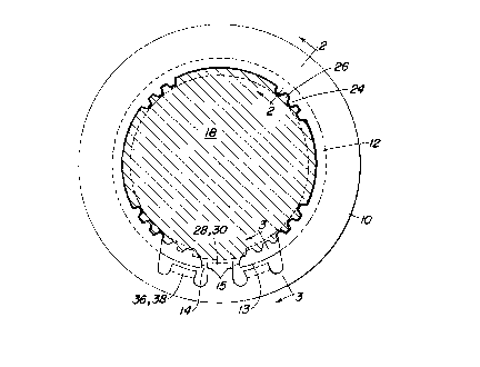
FIG. 2 is a sectional view taken substantially along line
2-2 of FIG. 1.
FIG. 3 is a sectional view taken substantially along line
3-3 of FIG. 1.
Detailed Description of the
Preferred Embodiments of the Invention
As shown in the drawings for purposes of illustration,
the present invention is embodied in a washer 10 for retaining
a snap ring 12. The snap ring 12 has a radially outer surface
.~ .

21 52843
13 and a gap 14 that is defined by ends 15. The snap ring 12
is positioned in an annular groove 16 formed on a shaft 18 and
may support or retain another member, such as a rolling
bearing 20, on the shaft 18. The washer 10 preferably is
positioned between the snap ring 12 and the rolling bearing
20. For example, the rolling bearing 20 may be a tapered
roller bearing that is supported by the snap ring 12 where the
washer 10 separates the snap ring 12 from the tapered roller
bearing.
The washer 10 includes a tab or a tooth 24 that is
interlocked with a spline 26 formed on the shaft 18.
Preferably, the washer 10 has a plurality of teeth 24 that
engage a plurality of splines 26 extending substantially
parallel to the axis of the shaft 18. As shown in FIG. 1, the
gap 14 may overlap some of the splines 26. Preferably, the
splines 26 are formed on the shaft 18 in a symmetrical
distribution of groups that cooperate with the arrangement of
the teeth 24 to make assembly of the washer 10 onto the shaft
18 easier by permitting several different installation
orientations of the teeth 24 relative to the splines 26.
The washer 10 includes a tab or a stop 28 that is nested
in the gap 14. The stop 28 is formed as a tab 30 that
includes a bent substantially radially extending leg 32 and a
foot 34 that extend substantially parallel to the axis of the
shaft 18. The foot 34 projects into the gap 14 for engagement
with the ends 15 of the snap ring 12 in order to prevent
rotation of the snap ring 12 relative to the washer 10.
Also, the washer 10 includes at least one tab or catch 36
that flanks the stop 28 and overlaps the snap ring 12 near the
gap 14. As shown in FIG. 1, there preferably is a catch 36 on
each side of the stop 28 such that each end of the snap ring
12 on each side of the gap 14 is overlapped by one of the pair
of catches 36. By overlapped, it is meant that the catch 36
is positioned radially outwardly with respect to the outer
surface 13 of the snap ring 12. Each catch 36 is formed as a
bent tab 38 that includes a substantially radially extending
arm 40 and a finger 42 that extends substantially parallel to

21 52843
the axis of the shaft 18. The finger 42 of each of the
catches 36 projects over the outer surface 13 of the snap ring
12 in order to prevent displacement of the snap ring 12 from
out of the groove 16. Preferably, each catch 36 is formed to
extend a few millimeters radially outside the outer surface 13
of the snap ring 12.
The washer 10 is installed on the shaft 18 as follows.
The snap ring 12 is positioned in the groove 16 of the shaft
18. Also, the snap ring 12 is oriented in the groove 16 of
the shaft 18 such that the gap 14 of the snap ring 12 can
receive the stop 28 of the washer 10 upon installation of the
washer 10. Then, the washer 10 is installed on the shaft 18
adjacent to the snap ring 12. The teeth 24 of the washer 10
interlock with the splines 26 of the shaft 18. In addition,
the stop 28 of the washer 10 nests in the gap 14 of the snap
ring 12. Furthermore, the catches 36 of the washer 10 overlap
the snap ring 12. Next, the rolling bearing 20 is installed
on the shaft 18 adjacent to the washer 10. Preferably, the
cone 50 and the rollers 52 of the rolling bearing 20 are
20 installed on the shaft 18 adjacent to the washer 10. The cup
54 of the rolling bearing 20 is pre-installed in a housing
(not shown) of the transmission (not shown). The shaft 18
supporting the snap ring 12, the washer 10 and the cone 50 and
the rollers 52 of the rolling bearing 20 are installed into
25 the housing (not shown) of the transmission (not shown) such
that the cone 50 and the rollers 52 of the rolling bearing 20
are assembled with the cup 54 of the rolling bearing 20.
In the preferred embodiment of the invention shown in the
drawings, rotation of the washer 10 is prevented by
30 interlocking the teeth 24 and the splines 26. Furthermore,
rotation of the washer 10 can be prevented in various known
ways. For example, a tooth may project radially outwardly
from the shaft 18 and into a notch formed in the washer 10.
Alternatively, the shaft 18 and the washer 10 may be formed
35 with mating flats. Or, the shaft 18 and the washer 10 may
include matched keyways into which a key is placed.

21 52843
In this disclosure, there are shown and described several
embodiments of the invention, but it is to be understood that
the invention is capable of use in various other combinations
and environments and is capable of changes or modifications
within the scope of the inventive concept as expressed herein.

Representative Drawing
A single figure which represents the drawing illustrating the invention.
Administrative Status

2024-08-01:As part of the Next Generation Patents (NGP) transition, the Canadian Patents Database (CPD) now contains a more detailed Event History, which replicates the Event Log of our new back-office solution.

Please note that "Inactive:" events refers to events no longer in use in our new back-office solution.

For a clearer understanding of the status of the application/patent presented on this page, the site Disclaimer , as well as the definitions for Patent , Event History , Maintenance Fee  and Payment History  should be consulted.

Event History

Description Date
Inactive: IPC from MCD 2006-03-11
Time Limit for Reversal Expired 2002-06-28
Letter Sent 2001-06-28
Grant by Issuance 1998-11-24
Inactive: Delete abandonment 1998-08-13
Deemed Abandoned - Conditions for Grant Determined Not Compliant 1998-05-13
Inactive: Final fee received 1998-04-16
Pre-grant 1998-04-16
Notice of Allowance is Issued 1997-11-13
Letter Sent 1997-11-13
Notice of Allowance is Issued 1997-11-13
Inactive: Status info is complete as of Log entry date 1997-11-11
Inactive: Application prosecuted on TS as of Log entry date 1997-11-11
Inactive: Approved for allowance (AFA) 1997-09-11
Application Published (Open to Public Inspection) 1996-01-13
Request for Examination Requirements Determined Compliant 1995-06-28
All Requirements for Examination Determined Compliant 1995-06-28

Abandonment History

Abandonment Date Reason Reinstatement Date
1998-05-13

Maintenance Fee

The last payment was received on 1998-06-26

Note : If the full payment has not been received on or before the date indicated, a further fee may be required which may be one of the following

  • the reinstatement fee;
  • the late payment fee; or
  • additional fee to reverse deemed expiry.

Please refer to the CIPO Patent Fees web page to see all current fee amounts.

Fee History

Fee Type Anniversary Year Due Date Paid Date
MF (application, 2nd anniv.) - standard 02 1997-06-30 1997-06-27
Final fee - standard 1998-04-16
MF (application, 3rd anniv.) - standard 03 1998-06-29 1998-06-26
MF (patent, 4th anniv.) - standard 1999-06-28 1999-06-25
MF (patent, 5th anniv.) - standard 2000-06-28 2000-06-27
Owners on Record

Note: Records showing the ownership history in alphabetical order.

Current Owners on Record
DEERE & COMPANY
Past Owners on Record
DUANE FREDRICK MEYER
Past Owners that do not appear in the "Owners on Record" listing will appear in other documentation within the application.
Documents

To view selected files, please enter reCAPTCHA code :


To view images, click a link in the Document Description column. To download the documents, select one or more checkboxes in the first column and then click the "Download Selected in PDF format (Zip Archive)" or the "Download Selected as Single PDF" button.

List of published and non-published patent-specific documents on the CPD .

If you have any difficulty accessing content, you can call the Client Service Centre at 1-866-997-1936 or send them an e-mail at CIPO Client Service Centre.


Document
Description 
Date
(yyyy-mm-dd) 
Number of pages   Size of Image (KB) 
Representative drawing 1998-11-20 1 14
Cover Page 1996-04-29 1 16
Abstract 1996-01-13 1 15
Description 1996-01-13 5 208
Claims 1996-01-13 2 79
Drawings 1996-01-13 1 36
Cover Page 1998-11-20 1 44
Abstract 1997-08-13 1 14
Description 1997-08-13 5 205
Claims 1997-08-13 2 78
Commissioner's Notice - Application Found Allowable 1997-11-13 1 165
Maintenance Fee Notice 2001-07-26 1 178
Correspondence 1998-04-16 1 36
Prosecution correspondence 1995-06-28 10 382
Prosecution correspondence 1996-01-12 2 45