Sélection de la langue

Search

Sommaire du brevet 2152843 

Énoncé de désistement de responsabilité concernant l'information provenant de tiers

Une partie des informations de ce site Web a été fournie par des sources externes. Le gouvernement du Canada n'assume aucune responsabilité concernant la précision, l'actualité ou la fiabilité des informations fournies par les sources externes. Les utilisateurs qui désirent employer cette information devraient consulter directement la source des informations. Le contenu fourni par les sources externes n'est pas assujetti aux exigences sur les langues officielles, la protection des renseignements personnels et l'accessibilité.

Disponibilité de l'Abrégé et des Revendications

L'apparition de différences dans le texte et l'image des Revendications et de l'Abrégé dépend du moment auquel le document est publié. Les textes des Revendications et de l'Abrégé sont affichés :

  • lorsque la demande peut être examinée par le public;
  • lorsque le brevet est émis (délivrance).
(12) Brevet: (11) CA 2152843
(54) Titre français: RONDELLE DE RETENUE DE BAGUE A RESSORT
(54) Titre anglais: SNAP RING RETAINING WASHER
Statut: Périmé et au-delà du délai pour l’annulation
Données bibliographiques
(51) Classification internationale des brevets (CIB):
  • F16B 43/00 (2006.01)
  • F16B 21/18 (2006.01)
  • F16C 35/063 (2006.01)
(72) Inventeurs :
  • MEYER, DUANE FREDRICK (Etats-Unis d'Amérique)
(73) Titulaires :
  • DEERE & COMPANY
(71) Demandeurs :
  • DEERE & COMPANY (Etats-Unis d'Amérique)
(74) Agent: BORDEN LADNER GERVAIS LLP
(74) Co-agent:
(45) Délivré: 1998-11-24
(22) Date de dépôt: 1995-06-28
(41) Mise à la disponibilité du public: 1996-01-13
Requête d'examen: 1995-06-28
Licence disponible: S.O.
Cédé au domaine public: S.O.
(25) Langue des documents déposés: Anglais

Traité de coopération en matière de brevets (PCT): Non

(30) Données de priorité de la demande:
Numéro de la demande Pays / territoire Date
08/274,090 (Etats-Unis d'Amérique) 1994-07-12

Abrégés

Abrégé français

L'invention porte sur une rondelle comprenant au moins une dent interverrouillée avec une cannelure mâle d'une tige afin d'empêcher la rondelle de tourner relativement à la tige. Une bague à ressort est placée dans une rainure de la tige. La rondelle comporte une butée nichée dans un espace de la bague à ressort afin d'empêcher cette dernière de tourner par rapport à la tige. De préférence, la rondelle inclut au moins un crochet qui flanque la butée et chevauche la bague à ressort pour retenir cette dernière dans la rainure.


Abrégé anglais


A washer includes at least one tooth interlocked with a
spline of a shaft in order to retain the washer from rotating
relative to the shaft. A snap ring is positioned in a groove
of the shaft. The washer includes a stop nested in a gap of
the snap ring in order to retain the snap ring from rotating
relative to the shaft. Preferably, the washer includes at
least one catch that flanks the stop and overlaps the snap
ring in order to retain the snap ring in the groove.

Revendications

Note : Les revendications sont présentées dans la langue officielle dans laquelle elles ont été soumises.


THE EMBODIMENTS OF THE INVENTION IN WHICH AN EXCLUSIVE
PROPERTY OR PRIVILEGE IS CLAIMED ARE DEFINED AS FOLLOWS:
1. A washer for retaining a snap ring in an annular
groove of a shaft, the shaft having at least one axially
extending spline and the snap ring having opposed ends that
define a gap, the washer comprising:
a substantially flat, annular body adapted to be
positioned on the shaft adjacent to the snap ring;
at least one tooth extending from the body for
interlocking with the spline of the shaft in order to retain
the body from rotating relative to the shaft; and
a stop extending from the body including a substantially
radially extending leg and a foot that extends substantially
perpendicularly from the leg for nesting in the gap in order
to retain the snap ring from rotating relative to the shaft.
2. A washer for retaining a snap ring in an annular
groove of a shaft, the shaft having at least one axially
extending spline and the snap ring having opposed ends that
define a gap, the washer comprising:
a substantially flat, annular body adapted to be
positioned on the shaft adjacent to the snap ring;
at least one tooth extending from the body for
interlocking with the spline of the shaft in order to retain
the body from rotating relative to the shaft;
a stop extending from the body for nesting in the gap in
order to retain the snap ring from rotating relative to the
shaft, and
at least one catch projecting from the body for
overlapping the snap ring in order to retain the snap ring in
the groove.
3. The washer of claim 2, wherein:
the catch includes a bent, radially inwardly projecting
tab.
4. The washer of claim 2, wherein:
the catch includes a substantially radially extending arm
that terminates in a finger that extends substantially
perpendicular from the arm.
5. In combination with a shaft and a snap ring, the
shaft having an annular groove and an axially extending

spline, and the snap ring being positioned in the groove and
having opposed ends defining a gap therebetween, a washer
comprising:
a substantially flat, annular body formed to be
positioned on the shaft adjacent to the snap ring;
a tooth that extends substantially radially from the body
for interlocking with the spline in order to retain the body
from rotating relative to the shaft;
a stop that extends from the body and into the gap for
engagement with the opposed ends in order to retain the snap
ring from rotating relative to the shaft; and
at least one catch extending from the body for
overlapping the snap ring in order to retain the snap ring in
the groove.
6. The combination of claim 5, wherein the shaft
includes a plurality of axially extending splines, and the
body includes a plurality of substantially radially extending
teeth engaged with the splines.
7. The combination of claim 5, wherein the washer
includes a pair of catches, each one of the catches being
positioned on one side of the gap, and each of the catches
having a substantially radially extending arm and a finger
that extends substantially perpendicularly from the arm.

Description

Note : Les descriptions sont présentées dans la langue officielle dans laquelle elles ont été soumises.

21 52843
SNAP RING RETAINING WASHER
Technical Field
The invention relates generally to washers for retaining
a snap ring, and more particularly to washers for retaining a
snap ring from rotation relative to a shaft.
Background Art
Snap rings are often installed in a groove of a shaft.
Commonly, the snap ring is of an annular shape that is broken
by an opening or a gap. Thus, the shape of the snap ring
broadly may resemble the letter "C." Usually, the snap ring
provides a shoulder for supporting or retaining another
member, such as a rolling bearing, on the shaft. For example,
a tapered roller bearing may be seated against the snap ring
on the shaft of a work vehicle transmission. Unfortunately,
the snap ring may turn or rotate relative to the shaft,
resulting in wear of the snap ring.
Rotation of the snap ring may adversely affect the member
it supports or retains on the shaft. For instance, after
tapered roller bearings are installed on the shaft, an axial
adjustment is needed in order to provide a proper bearing
running clearance between the respective cones and cups. Wear
of the snap ring or the walls of the groove of the shaft
caused by rotation of the snap ring relative to the shaft may
result in loosening of the bearing setting or reduction in
operating efficiency.
One design has installed a thrust washer on the shaft
between the snap ring and the tapered roller bearing.
Shortcomings of this design include possible rotation of the
snap ring relative to the shaft, wear of the snap ring and
washer, and loosening of the setting of the tapered roller
bearlng.
Another design has provided a lock washer having tabs
bent over peripheral edges of a spring type retainer, such as
the snap ring, in order to oppose radial distortion of the
retainer out of its position, such as in the groove of the
shaft, and prevent axial separation of the lock washer and the
retainer. Shortcomings of the design include possible
rotation of the retainer relative to the shaft and consequent

21 52843
wear of the retainer. A design of this type is shown in U.S.
Patent No. 4,459,119.
Summary of Invention
One object of the invention is to reduce wear of a snap
ring.
Another object is to retain a snap ring from rotation
relative to a shaft.
A further object of the invention is to fix a snap ring
in a groove of a shaft.
According to the present invention, the foregoing and
other objects and advantages are attained by providing a
washer that includes at least one tooth interlocked with a
spline on a shaft in order to retain the washer from rotating
relative to the shaft. A stop is nested in a gap of a snap
ring that is positioned in an annular groove formed on the
shaft in order to retain the snap ring from rotating relative
to the shaft. The washer includes at least one catch or tab
that overlaps the snap ring in order to retain the snap ring
in the groove.
Additional objects, advantages, and novel features of the
invention will become apparent to those skilled in the art
upon examination of the following detailed description of the
preferred embodiments of the invention when read in
conjunction with the accompanying drawings.
Brief Description of the Drawings
FIG. 1 is a view, partially in section, showing a washer
constructed according to the present invention and a snap ring
mounted on a shaft.
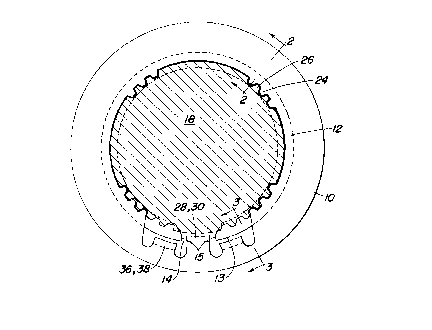
FIG. 2 is a sectional view taken substantially along line
2-2 of FIG. 1.
FIG. 3 is a sectional view taken substantially along line
3-3 of FIG. 1.
Detailed Description of the
Preferred Embodiments of the Invention
As shown in the drawings for purposes of illustration,
the present invention is embodied in a washer 10 for retaining
a snap ring 12. The snap ring 12 has a radially outer surface
.~ .

21 52843
13 and a gap 14 that is defined by ends 15. The snap ring 12
is positioned in an annular groove 16 formed on a shaft 18 and
may support or retain another member, such as a rolling
bearing 20, on the shaft 18. The washer 10 preferably is
positioned between the snap ring 12 and the rolling bearing
20. For example, the rolling bearing 20 may be a tapered
roller bearing that is supported by the snap ring 12 where the
washer 10 separates the snap ring 12 from the tapered roller
bearing.
The washer 10 includes a tab or a tooth 24 that is
interlocked with a spline 26 formed on the shaft 18.
Preferably, the washer 10 has a plurality of teeth 24 that
engage a plurality of splines 26 extending substantially
parallel to the axis of the shaft 18. As shown in FIG. 1, the
gap 14 may overlap some of the splines 26. Preferably, the
splines 26 are formed on the shaft 18 in a symmetrical
distribution of groups that cooperate with the arrangement of
the teeth 24 to make assembly of the washer 10 onto the shaft
18 easier by permitting several different installation
orientations of the teeth 24 relative to the splines 26.
The washer 10 includes a tab or a stop 28 that is nested
in the gap 14. The stop 28 is formed as a tab 30 that
includes a bent substantially radially extending leg 32 and a
foot 34 that extend substantially parallel to the axis of the
shaft 18. The foot 34 projects into the gap 14 for engagement
with the ends 15 of the snap ring 12 in order to prevent
rotation of the snap ring 12 relative to the washer 10.
Also, the washer 10 includes at least one tab or catch 36
that flanks the stop 28 and overlaps the snap ring 12 near the
gap 14. As shown in FIG. 1, there preferably is a catch 36 on
each side of the stop 28 such that each end of the snap ring
12 on each side of the gap 14 is overlapped by one of the pair
of catches 36. By overlapped, it is meant that the catch 36
is positioned radially outwardly with respect to the outer
surface 13 of the snap ring 12. Each catch 36 is formed as a
bent tab 38 that includes a substantially radially extending
arm 40 and a finger 42 that extends substantially parallel to

21 52843
the axis of the shaft 18. The finger 42 of each of the
catches 36 projects over the outer surface 13 of the snap ring
12 in order to prevent displacement of the snap ring 12 from
out of the groove 16. Preferably, each catch 36 is formed to
extend a few millimeters radially outside the outer surface 13
of the snap ring 12.
The washer 10 is installed on the shaft 18 as follows.
The snap ring 12 is positioned in the groove 16 of the shaft
18. Also, the snap ring 12 is oriented in the groove 16 of
the shaft 18 such that the gap 14 of the snap ring 12 can
receive the stop 28 of the washer 10 upon installation of the
washer 10. Then, the washer 10 is installed on the shaft 18
adjacent to the snap ring 12. The teeth 24 of the washer 10
interlock with the splines 26 of the shaft 18. In addition,
the stop 28 of the washer 10 nests in the gap 14 of the snap
ring 12. Furthermore, the catches 36 of the washer 10 overlap
the snap ring 12. Next, the rolling bearing 20 is installed
on the shaft 18 adjacent to the washer 10. Preferably, the
cone 50 and the rollers 52 of the rolling bearing 20 are
20 installed on the shaft 18 adjacent to the washer 10. The cup
54 of the rolling bearing 20 is pre-installed in a housing
(not shown) of the transmission (not shown). The shaft 18
supporting the snap ring 12, the washer 10 and the cone 50 and
the rollers 52 of the rolling bearing 20 are installed into
25 the housing (not shown) of the transmission (not shown) such
that the cone 50 and the rollers 52 of the rolling bearing 20
are assembled with the cup 54 of the rolling bearing 20.
In the preferred embodiment of the invention shown in the
drawings, rotation of the washer 10 is prevented by
30 interlocking the teeth 24 and the splines 26. Furthermore,
rotation of the washer 10 can be prevented in various known
ways. For example, a tooth may project radially outwardly
from the shaft 18 and into a notch formed in the washer 10.
Alternatively, the shaft 18 and the washer 10 may be formed
35 with mating flats. Or, the shaft 18 and the washer 10 may
include matched keyways into which a key is placed.

21 52843
In this disclosure, there are shown and described several
embodiments of the invention, but it is to be understood that
the invention is capable of use in various other combinations
and environments and is capable of changes or modifications
within the scope of the inventive concept as expressed herein.

Dessin représentatif
Une figure unique qui représente un dessin illustrant l'invention.
États administratifs

2024-08-01 : Dans le cadre de la transition vers les Brevets de nouvelle génération (BNG), la base de données sur les brevets canadiens (BDBC) contient désormais un Historique d'événement plus détaillé, qui reproduit le Journal des événements de notre nouvelle solution interne.

Veuillez noter que les événements débutant par « Inactive : » se réfèrent à des événements qui ne sont plus utilisés dans notre nouvelle solution interne.

Pour une meilleure compréhension de l'état de la demande ou brevet qui figure sur cette page, la rubrique Mise en garde , et les descriptions de Brevet , Historique d'événement , Taxes périodiques et Historique des paiements devraient être consultées.

Historique d'événement

Description Date
Inactive : CIB de MCD 2006-03-11
Le délai pour l'annulation est expiré 2002-06-28
Lettre envoyée 2001-06-28
Accordé par délivrance 1998-11-24
Inactive : Supprimer l'abandon 1998-08-13
Réputée abandonnée - les conditions pour l'octroi - jugée non conforme 1998-05-13
Inactive : Taxe finale reçue 1998-04-16
Préoctroi 1998-04-16
Un avis d'acceptation est envoyé 1997-11-13
Lettre envoyée 1997-11-13
Un avis d'acceptation est envoyé 1997-11-13
Inactive : Renseign. sur l'état - Complets dès date d'ent. journ. 1997-11-11
Inactive : Dem. traitée sur TS dès date d'ent. journal 1997-11-11
Inactive : Approuvée aux fins d'acceptation (AFA) 1997-09-11
Demande publiée (accessible au public) 1996-01-13
Exigences pour une requête d'examen - jugée conforme 1995-06-28
Toutes les exigences pour l'examen - jugée conforme 1995-06-28

Historique d'abandonnement

Date d'abandonnement Raison Date de rétablissement
1998-05-13

Taxes périodiques

Le dernier paiement a été reçu le 1998-06-26

Avis : Si le paiement en totalité n'a pas été reçu au plus tard à la date indiquée, une taxe supplémentaire peut être imposée, soit une des taxes suivantes :

  • taxe de rétablissement ;
  • taxe pour paiement en souffrance ; ou
  • taxe additionnelle pour le renversement d'une péremption réputée.

Veuillez vous référer à la page web des taxes sur les brevets de l'OPIC pour voir tous les montants actuels des taxes.

Historique des taxes

Type de taxes Anniversaire Échéance Date payée
TM (demande, 2e anniv.) - générale 02 1997-06-30 1997-06-27
Taxe finale - générale 1998-04-16
TM (demande, 3e anniv.) - générale 03 1998-06-29 1998-06-26
TM (brevet, 4e anniv.) - générale 1999-06-28 1999-06-25
TM (brevet, 5e anniv.) - générale 2000-06-28 2000-06-27
Titulaires au dossier

Les titulaires actuels et antérieures au dossier sont affichés en ordre alphabétique.

Titulaires actuels au dossier
DEERE & COMPANY
Titulaires antérieures au dossier
DUANE FREDRICK MEYER
Les propriétaires antérieurs qui ne figurent pas dans la liste des « Propriétaires au dossier » apparaîtront dans d'autres documents au dossier.
Documents

Pour visionner les fichiers sélectionnés, entrer le code reCAPTCHA :


Pour visualiser une image, cliquer sur un lien dans la colonne description du document. Pour télécharger l'image (les images), cliquer l'une ou plusieurs cases à cocher dans la première colonne et ensuite cliquer sur le bouton "Télécharger sélection en format PDF (archive Zip)" ou le bouton "Télécharger sélection (en un fichier PDF fusionné)".

Liste des documents de brevet publiés et non publiés sur la BDBC .

Si vous avez des difficultés à accéder au contenu, veuillez communiquer avec le Centre de services à la clientèle au 1-866-997-1936, ou envoyer un courriel au Centre de service à la clientèle de l'OPIC.


Description du
Document 
Date
(aaaa-mm-jj) 
Nombre de pages   Taille de l'image (Ko) 
Dessin représentatif 1998-11-20 1 14
Page couverture 1996-04-29 1 16
Abrégé 1996-01-13 1 15
Description 1996-01-13 5 208
Revendications 1996-01-13 2 79
Dessins 1996-01-13 1 36
Page couverture 1998-11-20 1 44
Abrégé 1997-08-13 1 14
Description 1997-08-13 5 205
Revendications 1997-08-13 2 78
Avis du commissaire - Demande jugée acceptable 1997-11-13 1 165
Avis concernant la taxe de maintien 2001-07-26 1 178
Correspondance 1998-04-16 1 36
Correspondance de la poursuite 1995-06-28 10 382
Correspondance de la poursuite 1996-01-12 2 45