Note: Descriptions are shown in the official language in which they were submitted.
CA 02154235 2002-02-22
~~~4~~J~
SYRINGE PLUNGER WITH
INTERMEDIATE PUSHING SURFACE
FIELD OF THE INVENTION:
The present invention relates generally to syringes, and more
particularly, to a plunger component with an intermediate pushing
surface which allows a user with small hands to administer the
contents of a syringe without stretching h.is or her hands
uncomfortably.
BACKGROUND OF THE INVENTION:
Syringes typically include a plunger which is a rigid stem used to
move a slidable piston axially through a solution-filled barrel to push
solution through a nozzle at the end of the barrel.
In order to ensure that all the solution in the barrel is
administered through the syringe nozzle, the plunl;er stem must be at
least as long as the syringe barrel. For small volume syringes, 5 cc and
10 cc syringes, for example, the syringe barrel may be approximately
three to four inches (3-4") long. Thus, the small volume syringe
plunger stem is often in the range of approximately three to four inches
long. Usually a user, even with small hands, can grasp the syringe
barrel at the flange tabs between two fingers and extend the thumb to
the distal end of the extending plunger stem. Then, when the user
applies force on the plunger pushing surface, the piston moves through
the barrel and solution is administered through the end nozzle.
However, for larger syringes, for example, 50 cc or 60 cc syringes,
the barrel is typically longer than four inches (4") and often longer than
five inches (5"). Consequently the plunger is also longer than
approximately four inches. A user with small hands will have great
difficulty in using these large syringes with only one hand. For
example, a person with small hands will have great difficulty in
positioning the wide diameter syringe barrel betwE~en two fingers and
firmly hold the barrel while extending the thumb rearward four inches
or more to the plunger pushing surface. Even if the user accomplishes
this stretch of the hand, the small handed user rnay have difficulty
CA 02154235 2002-02-22
2
generating enough axial force to push the plunger into the barrel to begin
administration of the solution.
Often a small handed user using a large volume syringe must resort to two
handed operation of the syringe. In many situations, two handed use limits the
user's ability to perform other tasks. These other tasks include opening or
closing
flow control devices, or other manipulation that are normally most efficiently
performed concurrent with the fluid administration. Thus, it is a disadvantage
to
have a large volume syringe that cannot be used by all users in the same one-
handed manner that is used for small volume syringes.
It is therefore desirable to provide a syringe plunger for large volume
syringes that would accommodate one-handed administration by small handed
people. Such a syringe plunger would enable a small handed person to perform
the procedures in an expected manner.
The present invention provides a syringe plunger with an intermediate
pushing surface positioned on the stem between the proximal end of the stem
and
the distal pushing surface of the stem that will accommodate one-handed
administration of most syringes by small handed persons.
SUMMARY OF THE INVENTION:
In accordance with the invention there is provided a syringe plunger for use
to
administer a solution from a syringe of the type having an axially slidable
piston
sealing an axially extending barrel, the plunger comprising: a rigid stem
member
axially extending from a distal end to a proximal end; means at i:he proximal
end of
the stem for attachment to a piston slidable in a barrel; a first surface at
the distal end
of the stem for application of axial force to the stem so as to move the
slidable piston
axially in the barrel; means at an axially intermediate position on the stem
for
alternative application of axial force to the stem so as to initially move the
slidable
piston axially in the barrel; and the stem member having a radial
configuration so as
to allow the slidable piston to be axially movable in the barrel without the
radial
configuration of the stem causing contact of the stem with the ban-el to limit
the axial
movement of the slidable piston.
,~ f,...: , ~i ~~
r r.
CA 02154235 2002-02-22
2a
The invention thus provides a syringe plunger for a syringe of the type
having an axially slidable piston in an axially extending barrel wherein the
plunger includes an axially extending rigid stem member having piston
attachment structure such as threads at a proximal end. At the distal end of
the
plunger stem member is a first pushing surface for application of axial force
by
the user so as to move the piston through the barrel. A second pushing surface
is
provided at an axially intermediate position on the plunger stem for the
alternative application of axial force to the stem by a user, for example,
with
small hands, so as to initially move the slidable piston in the barrel.
The plunger stem member is configured so as to allow the slidable piston
to be axially movable within the barrel without causing interfering or binding
contact of the stem with the barrel which would thus prevent axial movement of
the piston.
r .. _, .
CA 02154235 2002-02-22
3
In a preferred embodiment of the syringe plunger, the first and
second or intermediate pushing surfaces are substantially perpendicular
to the axis of the stem. Furthermore, the intermediate surface is
positioned at approximately the axial midpoint of t'ihe stem.
The preferred embodiment of the syringe plunger also includes
an axial clearance space along at least one edge portion of the
intermediate pushing surface. The clearance space extends axially
through a radially central portion of the stem to form a cutout, for
example, so as to allow the thumb of the user to comfortably and fully
ICi contact the second pushing surface.
In a further embodiment of the syringe plunger, a predetermined
position on the plunger, such as the intermediate pushing surface can
be used to indicate that a preselected amount of solution has been
administered from the syringe. For example, when the axial position of
the intermediate pushing surface is axially coincident with a fixed
position on the syringe barrel, the coincident positions can be pre-
calibrated to indicate that a preselected amount of solution has been
administered.
Accordingly, when a small handed user initially administers a
2o first portion of the solution from a large volume syringe, the plunger
stem is pushed from the intermediate position by the thumb in a
comfortable manner without stretching the :hand. When the
intermediate pushing surface has been moved to coincide with the
fixed indicating position on the syringe barrel, the solution
administration can be temporarily stopped. Then the thumb can be
repositioned on the end pushing surface and the solution
administration can be completed.
Numerous other advantages and features of the present
invention will become readily apparent from the following description
3o of the invention, the claims, and the accompanying drawings.
BRIEF DESCRIPTION. OF THE DRAWINGS:
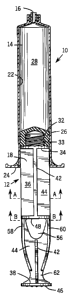
Figure 1 is a sectional view of a syringe including a solution
filled syringe barrel and an attached syringe plunger according to the
present invention.
5584.US.01
CA 02154235 2002-02-22
~1~4~3~
4
Figure 1a is a cross-sectional view of the syringe plunger at
section line a-a;
Figure 1b is a cross-sectional view of the cutout space of the
syringe plunger according to the present plunger at aection line b-b;
Figure 2 is a cross-sectional view of the syringe according to the
present invention showing a partial administration of the solution; and
Figure 3 is a cross-sectional view of the syringe plunger according
to the present invention showing a complete administration of the
solution.
DESCRIPTION OF THE PREFERRED EMBODIMENTS
While this invention is susceptible of embodiments in many
different forms, the specification and accompanying drawing discloses
only one specific form as an example of this invention. The invention
is not intended to be limited to the embodiment described, the scope of
the individual invention being pointed out in the appended claims.
Referring now to Figures 1-3, a syringe assembly 10 includes a
syringe plunger 12 according to the present invention and a barrel 14 of
conventional construction.
As such, the barrel 14 is preferably an axially extending cylinder
having an administration nozzle 16 at a proximal end and an open
distal end, generally indicated at 18. The barrel is preferably molded of a
suitable plastic material or formed of glass so as to be compatible with
the solutions to be administered. The barrel also includes a smooth,
interior sidewall 22 which extends the whole length of the barrel.
Radially extending barrel flange tabs 24 may be provided at or near the
distal end of the barrel.
A sealingly slidable piston 26 is fitted in the distal end of the
syringe barrel. The piston is preferably molded of an elastomeric
material. The piston is constructed and arranged for sealing and sliding
contact with the interior sidewall 22 of the syringe barrel. A removable
nozzle cap (not shown) seals the nozzle 16. Thus, a sealed solution
chamber 28 is formed in the open-ended barrel 14 by the nozzle 16 and
nozzle cap, the interior sidewall 22 of the barrel, and the sealingly
slidable piston 26.
ssss.us.oi
CA 02154235 2002-02-22
~1~~~3~
To administer the solution through the nozzle 16, the
elastomeric piston 26 is moved from the distal end of the barrel to the
proximal end of the barrel, forcing the solution through the nozzle.
The rigid, axially extending plunger stem member 1.2, is utilized to push
5 the piston to the proximal end of the syringe barrel. In a preferred
embodiment of the plunger, structure such as threads 32 at the
proximal end of the plunger stem are provided for removable
attachment to the piston 26, such as, by mating threads 33 in the distal
face of the piston. Other attachment structure includes, for example, a
radial flange on the proximal end of the stem that can mate with an
undercut in the piston. An embodiment of this type, however, results
in a plunger-piston connection that is less detachable than the threaded
type.
The attaching construction is positioned at a radial flange 34 on
i5 the proximal end of the plunger stem. The stem ;:46 is a rigid, axially-
extending construction whose length is usually greater than the length
of the syringe barrel 14. The stem ends in a second radial flange 38 at
the distal end of the stem. In the preferred embodiment of the plunger,
the stem is constructed of two axially-extending rib members 42 and 44.
The rib members 42 and 44 perpendicularly intersect along the axis of
the stem to provide for the structural rigidity of the stem. This
conventional intersecting rib construction reduces the amount of
material and cost necessary to produce an acceptable rigid structure.
The intersecting rib construction can be best seen in the cross-section of
Figure 1a. Other rigid stem construction such as a hollow cylinder is
also considered to be with the scope of the invention.
An end pushing surface 46 is located at the distal end of the stem.
An intermediate pushing surface 48 is conveniently located on the
plunger at approximately the midpoint between the proximal end and
3o the distal end of the plunger. The pushing surfaces 46 and 48 are
substantially perpendicular to the axis of the plunger stem.
As seen in Figure lb, the intermediate push surface 48 has an
axially cleared space along at least one edge portion of the perpendicular
surface as shown generally by 52 and/or 54. Notably, structural rib 42 as
seen in Figure 1 and Figure 1a, is axially interrupted. as shown in Figure
1b, so as to produce a radially flat intermediate surface 48 which is
5584.US.01
CA 02154235 2002-02-22
~1~4~~~
6
perpendicular to the axis of the stem 36. The flat surfacE~ is large enough
to accommodate the thumb of the syringe user. As seen with reference
to Figure l, the flat surface of the axial clearance space 52/54 also extends
through a radially central portion of the stem as shown by the cutout 56.
Thus, the central portion of rib 44 is also interrupted on the distal side
of the intermediate push surface 48.
To structurally compensate For the complete removal of
structural rib 42 and th.e substantial removal of the center portion of rib
44 at the cutout space 56, side ribs 58 and 60 are added substantially
parallel to and overlapping the removed portion of rib 42. The side ribs
58 and 60 compensate for the loss of rib structure material at the center
portions of the stem.
The distal end of the plunger stem 12 is also provided with a
waist portion 62 which allows the plunger stem to be pulled back if it is
desired that the syringe also perform aspiration as well as
administration of solution.
In operation, a syringe which includes the syringe plunger 12 of
the present invention is advantageously used as follows. A syringe
barrel 14 and the syringe plunger 12 of the present invention are
assembled together and filled as shown in Figure 1. To administer the
solution in the syringe, a user typically holds the syringe barrel 14
between two fingers at the barrel flange tabs 24. The user then extends
his or her thumb to apply axial force to the end pushing surface 46 on
the syringe plunger. If the syringe is small enough in size and/or the
user's hands are large enough, the user can comfortably push on the
end pushing surface 46.
However, for large syringes having long barrel and plunger stem
lengths and/or for users having small hands, the user may be more
comfortable initially applying axial force with his ~or her thumb at the
intermediate pushing surface 48. The user can continue pushing at 48
until the intermediate surface is axially coincident with the end of the
barrel such as at the flange tabs 24 as shown in Figure 2.
The coincidence of the intermediate push surface and the flange
tabs can be readily used as a convenient indicator that: a predetermined
amount of solution or pre-selected fraction of a dose has been
administered from the syringe. For example, with the proper structural
sss.e.us.o~
CA 02154235 2002-02-22
~1~4'~35
dimensioning of the axial position of the intermediate surface 48 on the
stem, the concurrence of the intermediate surface 48 and the flange tabs
24 can indicate that one half of the solution in tree syringe has been
administered. Different and multiple pre-selected indicating structures
on the plunger stem 36 can be provided to indicate various portions of
the full solution dose, such as one quarter, one half and/or three
quarters dose, have been administered.
At the half-way point in the administration of the solution, for
example, the user can now comfortably reposition his or her thumb on
the distal pushing surface 46 and continue the aclm:inistration of the
fluid through the nozzle as shown in Figure 3.
The syringe plunger of the present invention <:an be used with
any syringe or other axially movable device that is movable by an
axially-applied force. The intermediate push position ,plunger 12 of the
present invention was primarily developed for use with large volume
syringes of the 50 or 60 cc volume type, speeificall.y, medical solution
syringes. For these type of syringes, a standard syringe barrel 14 may be
in excess of four to five inches (4-5") which requires that the syringe
plunger be on the order of greater than four to five inches. A person
with small hands may find it uncomfortable and be unable to apply the
required axial force with one hand when the syringe barrel 14 is held
between two fingers and the thumb is extended to push on the end
pushing surface 46 of such a long plunger stem.
Thus, it is believed that the addition of the intermediate pushing
surface 48 of the present invention to the plunger 12 allows a small
handed person to comfortably and with reasonable effort administer
solutions from large volume syringes. The intermediate pushing
surface is preferably located at approximately the midpoint of the
plunger stem and thus is only two to three inches (2-3") from the flange
tabs and/or the end of the barrel. The axial cutout 56 at the
intermediate surface is approximately one half to one inch (2 -1") in
height. Thus, a small handed user can comfortably use a larger volume
syringe in a manner similar to the conventional one handed manner
used with small volume syringes. This, for example, can be important
in medical situations since medical protocols and procedures for the
administration of solutions via syringes are often established which
5584.US.01
CA 02154235 2002-02-22
require one hand for the push administration while the other hand is
free to manipulate other associated medical devices, such as fluid flow
controllers, or to attend to the patient, for example.
The intermediate pushing surface and/or dose indicating means
of the present invention involves no extra material, parts or
manufacturing effort and is therefore essentially cost free. Either or
both can be used instantly without any pre-adjustrnent. Either or both
can be ignored if not needed with no penalty in con.ve:nience or cost.
It will be readily apparent from the foregoing detailed description
of the invention and from the illustrations thereof that numerous
variations and modifications may be affected without the departing
from the true spirit and scope of the novel concerts and principals of
this invention.
sss4.us.or