Note: Descriptions are shown in the official language in which they were submitted.
- 2 ~ 54 ~8Q
The present invention relates to a
continuously cast slab of extremely low carbon steel
exhibiting less surface defects in the production of
steel sheets, to an extremely low carbon sheet steel
as well as to a process for producing the same. More
particularly, the invention relates to an extremely low
carbon sheet steel with a good shapability. Thus, the
present invention relates not only to iron-making
technology for producing steel sheets, but also to a
broad range of industrial applications including
automobiles, household electric appliances, housing
materials, etc.
Extremely low carbon steel produced by
reducing the carbon content of steel refined in the
steel-making process to a few 10 ppm in a vacuum
degassing apparatus such as RH, etc., and further by
adding carbide-nitride-forming elements such as Ti, Nb,
etc. thereto, thereby fixing the remaining carbon, that
is, the so-called IF steel (interstitial free steel)
has a very excellent formability such as deep drawing,
etc. and is now much used in automobile application,
etc. IF-based, high strength sheet steel, intensified
by adding solid solution-strengthening elements such as
P, Mn, etc. to the IF steel has also now established a
dominant position as the main steel species of high
strength sheet steels. However, the IF steel has
several process and product drawbacks.
A first process drawback resides in surface
defects. IF steel is vacuum degassed in the steel-
making process, and consequently the oxygen content is
increased owing to the C-O equilibrium, and thus
deoxidation is carried out. It is hard to completely
remove the deoxidation products, which are liable to
remain as inclusions.
Furthermore, solidification in the continuous
casting process substantially eliminates carbon, and
thus there are no coexisting solid-liquid zones
- ~ ~ s~ ~%g
substantially at all. Unstability such as a temperature
fluctuation, etc. is directly connected to unstability
of steel slab quality, resulting in deterioration of
surface properties. Furthermore, the IF steel can be
deemed to be nearly pure iron in the composition and
has a higher Ar3 transformation point. Thus, the hot
rolling finishing temperature must be made higher,
resulting in inevitable generation of surface defects.
This serious situation can be understood by a forum
"Technique to prevent surface defects in the hot
rolling and heavy plate rolling" held in No. 126 Autumn
Lecture Conference of Japan Iron and Steel Institute,
where IF steel was taken as the main subject (see, for
example, Lecture summary, CAMP-ISIJ, vol. 6, pp 1328-
1331 and pp 1332-1335). In spite of the forum, measures
to be taken were of on-the-spot type and allopathic and
no fundamental solution has as yet been found at all.
Other drawbacks include several types,
depending on differences in species of sheet steels and
surface treatment, such as cold rolled steel sheets,
electroplated steel sheets, and hot zinc-dipped steel
sheets. The IF steel is generally sensitive to the
nature of surface treatment. Particularly the iron-zinc
alloy coated steel ~galvannealed steel) is strongly
influenced by steel components. Thus, in case of cold
rolled steel sheets and galvannealed steel sheets, it
is an ordinary expedient to classify the IF steel,
depending on their purposes. For example, Nb-contained
IF steel having a better hot dip galvanizing property
is preferably used for the galvannealed products,
whereas Ti-containing IF steel having a high Lankford
value (plastic anisotropic ratio hereinafter referred
to as "r value") as an indicator of material quality,
particularly deep drawability is preferably used for
cold rolled steel sheet, as classified depending on the
purposes. This is true also of IF-based high strength
steel sheets. However, the minute classification of
5 ~ ~
steel species was against the mass production as the
basis of the iron and steel industries and largely
deteriorated the economy.
Furthermore, a satisfactory metallographic
structures cannot be obtained at the heat-influenced
parts of welded joints, because the IF steel is
extremely low carbon steel. Thus, the IF steel has such
a drawback that strength or fatigue characteristics is
deteriorated at sites subject to heat influence such as
sites subject to spot welding. To overcome the
drawback, some measures have been taken, for example,
to modify the component system tJapanese Patent No. 4-
2661). However, restriction to the component system to
this effect has given rise to another disadvantage such
as limited applications or a failure to completely
utilize its component system from the viewpoint of
workability, etc. and also to an economic loss due to
addition of alloying elements.
Many patent applications have been filed so
far relating to steel sheets comprising a plurality of
layers, as in the present invention. For example,
published Japanese patent application Nos. 4-191330 and
4-191331 disclose that a high strength such as a high
dent resistance, etc. can be obtained by using at least
one layer made from alloy steel containing a large
amount of C, Mn, Si, P, etc.
However, these inventions attempt to obtain
novel functions in the strength, formability, etc. by
substantially changing mechanical properties of the
surface layers and the inner layer. Thus, generally the
surface layers have a larger thickness or the surface
layers are set to have a higher strength. Japanese
Patent No. 6-47706 discloses a technique of surface
carburizing of the IF steel, where the product
carburized layer has a larger thickness and the
technique is not directed to overcoming of process
defects as in the present invention.
As to a process for producing a sheet steel
comprising a plurality of layers as in the present
invention, published Japanese patent application No.
63-108947, for example, discloses a process utilizing a
static magnetic field as a means for separatlng
different species of molten steel metals poured into a
mold, where the static magnetic field is so formed that
a line of magnetic force can be extended at a uniform
density over the entire width of molten slab in the
direction perpendicular to the casting direction, and
different species of molten metals are supplied to the
molten slab separated into an upper molten steel pool
and a lower molten steel pool by the generated static
magnetic field zone as a boundary. As a result of
suppressing intermixing of the upper and lower molten
steel pools by the static magnetic field, the metal of
the upper molten steel pool and the metal of the lower
molten steel pool can be separated from each other and
solidified individually as a surface layer and an inner
layer, respectively, to form a slab having a plurality
of layers.
It is an object of the present invention to
overcome the above drawbacks and more particularly:
1. The surface defects due to the fact that
IF sheet steels can be deemed to be nearly as pure iron
containing substantially no carbon;
2. The minute classification of steel species
into cold rolled steel sheets, electroplated steel
sheets and hot dip galvanized steel sheets due to use
of or differences in the surface treatment; and
3. The shortage of product strength such as
deterioration of fatigue characteristics at welded
parts,
thereby converting the IF-based sheet steels into a
basic material affirmed from the viewpoint of
properties and economy.
According to one aspect of the invention,
there is provided a continuously cast slab of extremely
low carbon steel comprising not more than 1.5 wt.% of
Si, not more than 2.0 wt.% of Mn, not more than 0.15
wt.% of P, 0.01 - 0.15 wt.% of Al and not more than
0.0050 wt.% of N, and wherein the cast slab has a
surface layer further containing 0.01 - 0.08 wt.% of C
present as a cementite, and an inner layer further
containing not more than 0.0050 wt.% of C and at least
one of 0.02 - 0.10 wt.% of Ti, 0.01 - 0.10 wt.% of Nb,
0.02 - 0.10 wt.% of V and 0.03 - 0.10 wt.% of Zr, the
carbon being present substantially as carbides of these
elements, and the balance being Fe and inevitable
impurities.
Preferably, the surface layer and the inner
layer each further contain 0.0001 - 0.0015 wt.% of B.
In a preferred embodiment of the invention,
the surface layer contains 0.01 - 0.08 wt.% of C as
cementite, 0.1 - 0.4 wt.% of Mn, not more than 0.08
wt.% of P and 0.01 - 0.10 wt.% of Al, and further
contains at least one of 0.01 - 0.08 wt.% of Ti and
0.01 - 0.08 wt.% of Nb when required, the balance being
Fe and inevitable impurities, and the inner layer
contains not more than 0.0050 wt.% of C, 0.1 - 0.4 wt.%
of Mn, not more than 0.08 wt.% of P and 0.01 - 0.10
wt.% of Al, and further contains at least one of 0.02 -
0.08 wt.% of Ti and 0.01 - 0.08 wt.% of Nb, the balance
being Fe and inevitable impurities. Preferably, the
surface layer and the inner layer each further contain
0.0001 - 0.0010 wt.% of B.
According to another preferred embodiment of
the invention, the total thickness of the surface layer
on both sides of the slab is 5 - 15% of that of the
inner layer, preferably 5.0 - 9.0%.
The present invention also provides, in
another aspect thereof, a process for producing a
continuously cast slab of extremely low carbon steel as
4i' 6~ ~ ~
-
defined above, comprising applying a direct current
magnetic field which crosses the thickness of the slab
at a lower level position in the casting direction than
the meniscus of molten steel poured into a continuously
casting mold, to the molten steel, thereby forming a
direct current magnetic field zone, and conducting
casting while separating the molten steel into an upper
molten steel pool and a lower molten steel pool by the
direct current magnetic field zone, thereby forming a
slab comprising a plurality of layers with a surface
layer and an inner layer having different steel
compositions. The process of the invention is
characterized by pouring molten steel containing not
more than 0.0050 wt.% of C, not more than 1.5 wt.% of
Si, not more than 2.0 wt.% of Mn, not more than 0.15
wt.% of P, 0.01 - - 0.15 wt.% of Al, and not more than
0.0050 wt.% of N, the balance being Fe and inevitable
impurities into the continuously casting mold,
supplying a carbon-containing powder to the surface of
the upper molten steel pool separated by the direct
current magnetic field zone, to thereby add 0.01 - 0.08
wt.% of C to the surface layer, and inserting an Fe-
coated alloy wire containing at least one of Ti, Nb, V
and Zr into the lower molten steel pool, to thereby add
at least one of 0.02 - 0.10 wt.% of Ti, 0.01 - 0.10
wt.% of Nb, 0.02 - 0.10 wt.% of V and 0.03 - 0.10 wt.%
of Zr to the inner layer.
Preferably, the surface layer and the inner
layer of the slab each further contain 0.0001 - 0.0015
wt.% of B.
In a preferred embodiment of the invention,
the molten steel poured into the casting mold contains
not more than 0.0025 wt.% of carbon, and the inner
layer contains 0.025 - 0.040 wt.% of Ti. The slab is
hot rolled at a temperature not exceeding 1,100~C.
Preferably, the inner layer of the slab further
contains 0.01 - 0.02 wt.% of Nb. The powder used in
-
such an embodiment preferably contains 0.5 - 10 wt.% of
C.
According to another preferred embodiment,
the molten steel poured into the casting mold contains
not more than 0.0050 wt.% of C, 0.1 - 0.4 wt.% of Mn,
not more than 0.08 wt.% of P and 0.01 - 0.10 wt.% of
Al, and further contains at least one of 0.01 - 0.08
wt.% of Ti and 0.01 - 0.08 wt.% of Nb, the balance
being Fe and inevitable impurities. Preferably, the
surface layer and the inner layer of the slab each
further contain 0.0001 - 0.0010 wt.% of B.
The powder used in such an embodiment
preferably contains 0.5 - 5 wt.% of C.
According to a further aspect of the
invention, there is provided an extremely low carbon
sheet steel comprising not more than 1.5 wt.% of Si,
not more than 2.0 wt.% of Mn, not more than 0.15 wt.%
of P, 0.01 - 0.15 wt.% of Al and not more than 0.0050
wt.% of N, and wherein the sheet steel has a surface
layer further containing 0.01 - 0.08 wt.% of C present
as a cementite, and an inner layer containing not more
than 0.0050 wt.% of C and further containing at least
one of 0.02 - 0.10 wt.% of Ti, 0.01 - 0.10 wt.% of Nb,
0.02 - 0.10 wt.% of V and 0.03 - 0.10 wt.% of Zr, the
carbon being present substantially as carbides of the
elements, and the balance being Fe and inevitable
impurities.
Preferably, the surface layer and the inner
layer of the sheet steel each contain 0.0001 - 0.0015
wt.% of B.
In a preferred embodiment of the invention,
the surface layer of the sheet steel contains 0.01 -
0.08 wt.% of C, 0.05 - 0.40 wt.% of Mn, 0.01 - 0.10
wt.% of Al and not more than 0.0050 wt.% of N, the
balance being Fe and inevitable impurity elements, and
the inner layer contains not more than 0.0050 wt.% of
C, 0.05 - 0.40 wt.% of Mn, 0.01 - 0.10 wt.% of Al, not
~ ~4~
more than 0.0050 wt.% of N and 0.02 - 0.08 wt.% of Ti,
the balance being Fe and inevitable impurity elements.
In another preferred embodiment, the surface
layer of the sheet steel contains 0.01 - 0.08 wt.% of
C, 0.05 - 0.40 wt.% of Mn, 0.01 - 0.10 wt.% of Al, not
more than 0.0050 wt.% of N and 0.0001 - 0.0010 wt.% of
B, the balance being Fe and inevitable impurity
elements, and the inner layer contains not more than
0.0050 wt.% of C, 0.05 - 0.40 wt.% of Mn, 0.01 - 0.10
wt.% of Al, not more than 0.0050 wt.% of N, 0.02 - 0.08
wt.% of Ti and 0.0001 - 0.0010 wt.% of B, the balance
being Fe and inevitable impurity elements.
According to a further preferred embodiment
of the invention, the surface layer of the sheet steel
contains 0.01 - 0.08 wt.% of C, 0.1 - 0.4 wt.% of Mn,
not more than 0.08 wt.% of P, 0.01 - 0.10 wt.% of Al
and further contains at least one of 0.01 - 0.08 wt.%
of Ti and 0.01 - 0.08 wt.% of Nb, if required, the
balance being Fe and inevitable impurities, and the
inner layer contains not more than 0.0050 wt.% of C,
0.1 - 0.4 wt.% of Mn, not more than 0.08 wt.% of P and
0.01 - 0.10 wt.% of Al, and further containing at least
one of 0.02 - 0.08 wt.% of Ti and 0.01 - 0.08 wt.% of
Nb, the balance being Fe and inevitable impurities.
Preferably, the surface layer and the inner layer of
the steel sheet each further contain 0.0001 - 0.0010
wt.% of B.
According to yet another preferred
embodiment, the total thickness of the surface layer on
both sides of the sheet steel is not more than 8% of
that of the inner layer, and preferably is 2 - 8% of
that of the inner layer.
The invention also provides, in a further
aspect thereof, a process for producing an extremely
low carbon sheet steel by continuous casting,
comprising applying a direct current magnetic field
which crosses the thickness of a slab at a lower level
- 9
position in the casting direction than the meniscus of
molten steel poured into a continuously casting mold,
to the molten steel, thereby forming a direct current
magnetic field zone, and conducting casting while
separating the molten steel into an upper molten steel
pool and a lower molten steel pool by the direct
current magnetic field zone, thereby forming a slab
comprising a plurality of layers with a surface layer
and an inner layer having different steel compositions.
The process of the invention is characterized by
pouring molten steel containing not more than 0.0050
wt.% of C, not more than 1.5 wt.% of Si, not more than
2.0 wt.~ of Mn, not more than 0.15 wt.% of P, 0.01 -
0.15 wt.% of Al and not more than 0.0050 wt.% of N, the
balance being Fe and inevitable impurities, into the
continuously casting mold, supplying carbon-containing
powder to the surface of the upper molten steel pool
separated by the direct current magnetic field zone, to
thereby add 0.01 - 0.08 wt.% of C to the surface layer,
inserting an Fe-coated alloy wire containing at least
one of Ti, Nb, V and Zr into the lower molten steel
pool, to thereby add at least one of 0.02 - 0.10 wt.%
of Ti, 0.01 - 0.10 wt.% of Nb, 0.02 - 0.10 wt.% of V
and 0.03 - 0.10 wt.% of Zr to the inner layer, thereby
obtaining a continuously cast slab of extremely low
carbon steel, and then sub~ecting the continuously cast
slab to hot rolling, or hot rolling - pickling - cold
rolling - recrystallization annealing or hot rolling -
pickling - cold rolling - surface treatment.
Preferably, the surface layer and the inner
layer of the slab each further contain 0.0001 - 0.0015
wt.% of B.
In a preferred embodiment of the invention,
molten steel containing not more than 0.0050 wt.% of C,
0.05 - 0.40 wt.% of Mn, 0.01 - 0.10 wt.% of Al and not
more than 0.0050 wt.% of N, the balance being Fe and
inevitable impurity elements, is produced and then
-- 10 --
subjected to continuous casting, thereby obtaining a
slab while providing an electromagnetic brake at a
mold, a C-containing powder is added to the surface of
the upper molten steel pool so that the surface layer
5 contains 0.01 - 0.08 wt.% of C, an Fe-coated wire of Ti
alloy is inserted into the lower molten steel pool so
that the inner layer contains 0.02 - 0.08 wt.% of Ti,
and then the slab is subjected to hot rolling.
Preferably, the molten steel further contains 0.0001 -
0.0010 wt.% of B.
According to another preferred embodiment,
the molten steel poured into the casting mold contains
not more than 0.0050 wt.% of C, 0.1 - 0.4 wt.% of Mn,
not more than 0.08 wt.% of P and 0.01 - 0.10 wt.% of
Al, and further contains at least one of 0.01 - 0.08
wt.% of Ti and 0.01 - 0.08 wt.% of Nb, the balance
being Fe and inevitable impurities. Preferably, the
surface layer and the inner layer of the slab each
further contains 0.0001 - 0.0010 wt.% of B.
According to a further preferred embodiment,
the hot rolling - pickling - cold rolling surface
treatment as well as the recrystallization annealing
and galganizing are carried out in a continuous hot dip
galvanizing line. Preferably, the treatment in the
continuous hot dip galvanizing line is carried out by
galvanizing and then alloying treatment to zinc phase.
According to yet another preferred
embodiment, the hot rolling is carried out on the
continuously cast slab by subjecting the slab to direct
hot rolling at 1,050 - 1,200~C or heating - rough
rolling - finish rolling, where the finish rolling end
temperature is above the Ar3 transformation point or
below the Ar3 transformation point within a range to
avoid a ridging-like skin roughening, followed by
cooling, coiling at about 550 - 690~C, further cooling,
pickling if required and an appropriate finishing
treatment, thereby obtaining a hot rolled steel sheet
5 ~ ~
_
or hot rolled coil. Preferably, the finish rolling end
temperature is [Ar3 transformation point - 20] - 950~C.
Preferably, in the hot rolling - pickling -
cold rolling - recrystallization annealing, cold
rolling is carried out by cold rolling the pickled, hot
rolled coil in a cold rolled ratio of 60 - 85%, and
conducting the recrystallization annealing by box
annealing under annealing conditions of 650 - 750~C for
1 - 20 hours, or by continuous annealing under
annealing conditions of 700 - gO0~C for 10 sec. to 10
min., thereby obtaining a cold rolled steel sheet or a
cold rolled coil.
Preferably, in the hot rolling - pickling -
cold rolling - surface treatment, the surface treatment
is carried out by passing the cold rolled coil through
an electrogalvanizing line or an electrogalvanizing-
alloying line, thereby obtaining a pure zinc coated
steel sheet or zinc alloy coated steel sheet.
In such an embodiment, the electrogalvanizing
is preferably pure zinc plating. The electro-
galvanizing-alloying is preferably plating of Zn - Ni
alloy containing zinc as the major component.
According to another preferred embodiment, in
the hot rolling - pickling - cold rolling - surface
treatment, the surface treatment is carried out by
passing the cold rolled coil through a continuous hot
dip galvanizing line under conditions of 700 - 900~C
for 10 sec. - 10 min., thereby obtaining a hot dip
galvanized steel sheet.
According to a further preferred embodiment,
in the hot rolling - pickling - cold rolling - surface
treatment, the surface treatment is carried out by
passing the cold rolled coil through a continuous hot
dip galvanizing line under conditions of 700 - 900~C
for 10 sec. - 10 min., thereby obtaining a hot dip
galvanized steel sheet and then making a galvannealed
steel sheet at a hot dipping temperature of 420
- 12 -
Z ~1 5 ~
_,,
480~C, under alloying conditions of 480 - 600~C for 1 -
60 sec., and in a modification rolling ratio of 0.2 -
2% and a zinc deposit of 20 - 120 g/m2.
The present invention is to effectively
utilize carbon-containing powder for keeping the upper
surface of molten steel hot in a continuously casting
operation. That is, an electromagnetic brake is
provided at the lower part of a continuously casting
mold to separate the surface layer and the inner layer
from each other by the electromagnetic brake effect.
Due to this action, carbon is introduced only into the
slab surface layer from the powder, and the surface
flaws or surface defects generated during the hot
rolling, cold rolling or annealing are completely
eliminated in the present invention. The surface
defects include various types, and the present
invention is effective over a wide range of surface
defects including ordinary defects of scale origin,
defects of liquid film embrittling, very small cracks
generated on the surface layer by heating for hot
rolling, fine flaws of scale origin, and flaws or
surface defects to appear in the later steps due to
remaining fine scales.
Furthermore, elimination of surface defects
can be expected by improvement of the solidification
state. That is, the conventional IF steel has an
extremely small solid-liquid coexisting region, when
viewed from its components, and small fluctuations in
the temperature give rise to fluctuations in the
solidified shell thickness and have an influence on
segregation, etc. on the solid-liquid boundary. Thus,
such defects as powder entrapping, longitudinal slab
cracking, etc. are liable to occur. Solidification in a
mold by adding carbon to the surface layer, as in the
present invention, is solidification of Fe-C alloy and
thus the solid-liquid coexisting region can be
sufficiently maintained, resulting in less occurrence
- 13 -
_
of heterogenous state and consequent considerable
decrease in the surface defects.
That is, in the present invention, the
surface layer is made to contain 0.01 - 0.08 wt.% of C
and brought substantially into a cementite, whereby the
surface layer can take a composition corresponding to
that of low carbon, aluminum-killed steel during the
solidification in the continuous casting mold,
resulting in shaping of the solidified shell into a
normal state, minimizing fine crackings on or
segregation in the surface layer of continuously cast
slab and reducing the source of surface defects. Then,
the ordinary IF steel as near as pure iron is liable to
seize on rolls, etc. during the hot rolling, whereas in
the present extremely low carbon steel, the carbide as
cementite in the slab dissolves and exists as solid
solution carbon, and thus hot rolling flaws due to less
presence of solid solution carbon never occur. The
presence of solid solution carbon and the presence of
cementite at a low temperature can give some
satisfactory strength at high, medium and ordinary
temperatures and generation of flaws when handled in
the subsequent steps is also reduced to as low as that
of ordinary low carbon, aluminum-killed steel.
Furthermore, the surface layer is made to
have a composition corresponding to the low carbon,
aluminum-killed steel, and thus the product
characteristics can be largely improved. The surface
layer of the conventional IF steel composition as near
as pure iron has a low fatigue strength at any cost.
The parts subjected to heat influenced by welding, etc.
undergo more severe deterioration. On the other hand,
in the present extremely low carbon steel, the surface
layer subject to fatigue or bending has a composition
corresponding to that of ordinary low carbon, aluminum-
killed steel, and thus the above-mentioned problems can
be substantially solved.
- 14 -
....~
Components for the inner layer and components
for surface layer excluding carbon are selected to
maintain the strength and processability as IF steel.
That is, the C content must be not more than
0.0050 wt.%, preferably not more than 0.0030 wt.%.
Above 0.0050 wt.%, satisfactory processability,
particularly the r value and elongation, are hard to
obtain.
Si is a solid solution-strengthening element
and not more than 1.5 wt.% of Si is suitable in the
case of high strength steel sheet. However, Si forms a
stable oxide film at a low temperature and is liable to
fail to undergo plating in the case of molten zinc
plating which must be subjected to reduction during the
annealing. From this point of view, it is desirable not
to use Si as much as possible. When used, Si should be
limited to the impurity level of mild steel sheet,
which is not more than 0.03 wt.%. However, so long as
some improvement in the reduction can be made, addition
of Si is not objectionable.
Not more than 2.0 wt.% of Mn, or 0.05 - 0.40
wt.% of Mn in the case of mild steel sheets, can be
present.
Mn is also a solid solution - strengthening
element and gives rather less deterioration of
elongation and r value, though it can effect the
strengthening. In the case of high strength steel
sheets, 0.20 - 2.0 wt.% of Mn must be present from this
point of view. Below 0.20 wt.%, no substantially
effective strengthening is obtainable by Mn. Below 0.05
wt.%, it is not sufficient to fix impurity S as MnS,
and the surface layer is liable to become brittle,
giving rise to surface defects during the hot rolling.
In the case of mild steel sheets, 0.05 - 0.25 wt.% of
Mn must be present.
The lower limit of Mn is selected so as to
fix impurity S as MnS. To be more stable, it is
~ ~ ~4 ~5
preferable that the inevitable impurity S be not more
than 0.011 wt.%, preferably not more than 0.010 wt.%,
and Mn/S be not less than 10.
P is also a solid solution-strengthening
element and is used to intensify steel in the case of
high strength steel sheets. However, P brings about
grain boundary embrittlement and promotes deterioration
of secondary workability, as will be described later,
and thus not more than 0.15 wt.% of P, desirably not
more than 0.08 wt.% of P must be present. In the case
of mild steel sheet, P is not required, and desirably
not more than 0.02 wt.% must be present.
Al is used as a deoxidizer and contained as
residues in steel. Below 0.01 wt.% of Al, no
satisfactory deoxidation can be obtained, and steel
inclusions are increased and appear as surface defects
or deteriorate the steel quality. Above 0.10 wt.% of
Al, on the other hand, the steel purity is
deteriorated, resulting also in the appearance of
surface defects and internal defects.
Not more than 0.0050 wt.% of N must be
present. Above 0.0050 wt.% of N, the presence of fine
nitrides such as AlN, etc. gives some influence upon
the steel recrystallization behavior, resulting in
deterioration of the steel quality.
The inner layer must contain at least one of
0.02 - 0.10 wt.%, preferably 0.02 - 0.08 wt.%, of Ti;
0.01 - 0.10 wt.%, preferably 0.01 - 0.08 wt.%, of Nb;
0.02 - 0.10 wt.% of V; and 0.03 - 0.10 wt.% of Zr to
fix solid solution carbon. Below the respective lower
limit values, no satisfactory carbon fixation can be
obtained and the inner layer can have no such
characteristics as those of IF steel. In that case, the
amount of Ti, Nb, etc. to be added is not a
stoichiometrically equivalent to carbon, but must be a
little more than the equivalent to carbon in view of
the rate, that is kinetics of carbide precipitation. At
- 16 -
~ ~1 5 ~
their respective upper limit values, their effect is
substantially saturated, and thus above their
respective upper limit values, economy is deteriorated.
These contents depend on the carbon content and
conditions in the successive steps. It is preferable as
a combination from the viewpoint of steel quality to
select not more than 0.0025 wt.% of carbon, and 0.025 -
0.040 wt.% of Ti as a carbide-forming element, and
restrict the heating temperature for the hot rolling to
not more than 1,100~C. When 0.01 - 0.02 wt.% of Nb is
contained, if any, under these conditions, a further
improvement in the steel quality can be expected.
In the case of sheet steels, embrittlement
due to secondary working takes place. That is, breakage
of shaped wall parts due to embrittlement or
characteristic defects call "planar cracking" sometimes
occurs when secondary working such as size enlargement,
etc. is carried out after the deep drawing operation.
The breakage seems to be due to deterioration of grain
boundary strength of IF steel, and can be overcome
by adding 0.0001 - 0.0015 wt.%, preferably 0.001 -
0.0010 wt.%, of B, when required. B seems to minimize
deterioration of steel quality and increase the grain
boundary strength. Below the lower limit value, no
effective improvement of secondary workability is
obtained. Above the upper limit value, deterioration of
steel quality becomes large. Preferably, not more than
0.0008 wt.% of B should be present.
Further features and advantages of the
invention will become more readily apparent from the
following description of preferred embodiments,
reference being made to the accompanying drawings, in
which:
FIG. 1 is a schematic view of a continuous
casting apparatus provided with an electromagnetic
brake and a wire feeder;
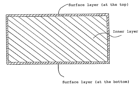
FIG. 2 is a schematic cross-sectional view
showing a slab according to the present invention;
FIG. 3 is a diagram showing distribution of C
component in the thickness direction of 1/4 width
region of a slab according to the invention; and
FIG. 4 is an S-N diagram showing fatigue test
results at a spot-welded joint.
To obtain a steel slab having the above-
mentioned composition, steel is produced in a
converter, and then steel containing not more than
0.0050 wt.% of C, not more than 1.5 wt.% of Si, not
more than 2.0 wt.% of Mn, and not more than 0.15 wt.%
of P, 0.01 - 0.15 wt.% of Al and not more than 0.0050
wt.% of N, the balance being Fe and inevitable
impurities, is produced in a vacuum degassing apparatus
and then subjected to continuous casting. The surface
layer is made from low C-Al-killed steel and has good
mechanical properties. The final product can contain a
surface layer having some thickness.
When at least one of Ti and Nb is added to
the surface layer on the other hand, precipitates such
as TiC are formed in the surface layer, making the
steel rigid. That is, the surface layer can be utilized
for improving the mechanical properties and protecting
the steel from defects in the successive steps. In that
case, it is preferable that the final product has no
remaining surface layer. On the other hand, when there
is the remaining surface layer, the mechanical
properties are deteriorated in proportion to the
presence of remaining surface layer. In the final
product, the surface layer must have as small a
thickness as nearly none, that is, such a thickness as
to be scaled off.
Addition of C to the surface layer and
addition of at least one of Ti, Nb, V and Zr to the
inner layer are carried out in a continuous casting
apparatus such as shown in FIG. 1. An electromagnetic
- 18 -
brake 2 is provided at a mold 1 of continuously casting
apparatus, and a direct current magnetic field crossing
the thickness of slab 6 is applied at a lower level
position in the casting direction than the meniscus of
molten steel poured into the continuously casting
apparatus 1 from a ladle 3 through a tundish 4 and an
immersion nozzle 5, to the molten steel, thereby
forming a direct current magnetic field zone. C-
containing powder 8 is supplied to the upper surface of
upper molten steel pool 7 separated by the direct
current magnetic field zone to add C to the surface
layer 9 of slab 6. Furthermore, Fe-coated alloy wire
containing at least one of Ti, Nb, V and Zr is inserted
into lower molten steel pool 10 by a wire feeder 11 to
add at least one of Ti, Nb, V and Zr to the inner layer
12 of slab 6. By carrying out the continuous casting in
this manner, the surface layer and the inner layer are
separated from each other by the effect of
electromagnetic brake to obtain a slab having a desired
composition. The alloy to be supplied from the wire is
so adjusted in the iron thickness coated on the wire,
feed rate, etc. so as to enter the lower pool in the
mold. A single wire or a plurality of wires can be
used. The wire can contain only Ti, Nb, V or Zr, or a
mixture thereof.
The powder contains 0.5 - 10 wt.%, preferably
0.5 - 5 wt.%, of C, and has a composition comprising,
for example, 29 wt.% of SiO2, 7 wt.% of Al2O3, 30 wt.%
of CaO, 13 wt.% of Na2O, 7 wt.% of F and 2.5 wt.% of
C.
Total thickness of the surface layer on both
sides in the slab is 5 - 15% of the thickness of the
inner layer. Below 5%, no surface layer effect is hard
to obtain, whereas, above 15%, no high processability
of inner layer can be obtained throughout. 5 - 10% or 5
- g.0% is preferable. Control of thickness of the
surface layer and the inner layer can be carried out
- 19 -
5 ~ ~
fully according to the already mentioned method.
Continuously casting of slab can be carried out by a
process of any type including a vertically bent type, a
horizontally bent type, etc. Continuous casting of even
a thin steel sheet having a thickness of about 50 mm is
not objectionable.
When hot scarfing or cold scarfing is applied
to the resulting slab, the thickness of high-carbon
surface layer should be controlled in view of a
scarfing allowance.
According to the present invention, the
source for the surface defects is reduced by producing
a surface layer having a higher carbon content in this
manner.
Hot rolling defects are hard to occur during
the hot rolling, because the present slab composition
contains ordinary carbon, the present slab is different
from soft extremely low carbon steel that is liable to
undergo seizure on rolls, etc. Different from extremely
low carbon steel, the present slab has a satisfactory
strength at high-middle-ordinary temperatures, and it
is expected that the generation of handling flaws in
the subsequent steps can be largely reduced.
Then, the steel slab is hot rolled. Hot
rolling is carried out by heating, rough rolling,
finish rolling, cooling at a run-out table, etc.,
followed by coiling. It is not objectionable that the
hot rolling is carried out by direct hot rolling (DR)
without passing through a heating furnace or by a hot
slab insertion method (HCR) based on insertion of a hot
slab into a heating furnace. In the case of passing
through a heating furnace, a conventional heating
temperature, such as 1,050 - 1,200~C, can be used.
The carbon-added region of the surface layer
can be mostly scaled off during the heating process.
Thus, the original thickness can be retained, as it is,
down to the final step, giving no adverse influence
- 20 -
8 ~
_
upon the steel quality. However, excessive scaling-off
reduces the effect of preventing surface defects, and
thus it is preferable that heating is carried out at a
temperature of not more than 1,150~C for a furnace
residence time of not more than 120 min. Heating at a
lower temperature than 1,100~C is preferable, because
the steel properties can be further improved.
Hot rolling can be carried out by any type,
for example, a full continuous type, semi-continuous
type, or their intermediate type. Finish rolling end
temperature must be usually above the Ar3
transformation point, but the rolling can be carried
out below the Ar3 transformation point within such a
range that no ridging-like skin roughening takes place.
Coiling temperature plays an important role in the
steel properties. The higher the coiling temperature,
the better the improvement. In this sense, it is
desirable that the coiling temperature be no less than
680~C
However, coiling at a higher temperature is
liable to form defects of pickling origin, and front
and tail ends of coil are quenched, resulting in
deterioration of steel properties at these porsions and
heterogeneous steel properties. Thus, it is preferable
that coiling temperature be 550 - 690~C. After the
coiling, the resulting coil is cooled and, when
required, pickled, and made into a hot rolled steel
sheet or a hot rolled coil through appropriate
finishing treatments and delivered to the market.
Pickled, hot rolled coil is cooled and then
subjected to recrystallization annealing to make the
cold rolled coil. Cold rolling reduction ratio can be
in a range of 60 - 85%, as usual. Recrystallization
annealing is carried out by box annealing or continuous
annealing. Annealing conditions are 650 - 750~C for 1 -
20 hours for the box annealing and 700 - 900~C for 10
seconds - 10 minutes for the continuous annealing. Any
- 21 -
_
type can be used for the box annealing and continuous
annealing. Cold rolled coil can be served as a cold
rolled steel sheet product directly, or passed through
an electrogalvanizing line to make an electro-
galvanized steel sheet. For the electrogalvanizing, notonly ordinary pure zinc plating, but also alloyed
galvanizing of Zn - Ni, etc. containing zinc as the
main component can be used.
Cold rolled coil can be passed through a
continuous hot dip galvanizing line to make a hot dip
galvanized steel sheet. In that case, heating
conditions are the same as those for the continuous
annealing.
For the hot dip galvanizing, use can be made
of the so-called galvannealing, whereafter dipping in a
zinc pot and reheating to 500~C, the resulting plating
layer is converted to an iron-zinc alloyed phase. In
that case, zinc adhesion and alloying state (in case of
galvannealing) are influenced by steel components, but
the surface layer improving effect of the present
invention can give a good influence upon the zinc
platability ~adhesion and alloying state).
That is, in the case of hot dip galvanizing
steel sheets, the zinc adhesion is influenced by steel
components, and in the case of galvannealing, the
alloying state is influenced thereby, and thus it is
necessary for the conventional IF steel, particularly
IF-based high strength steel sheet to take such steps
as selection of special component systems. In the
present invention, on the other hand, any special steps
are not required. Rather, it is not necessary to select
steel species such as hot rolled steel sheets, cold
rolled steel sheets and electrogalvanized steel sheets,
and this is one of the remarkable effects of the
present invention. Hot dip galvanized steel sheets or
galvannealed steel sheets have very good zinc adhesion
and alloying behavior of Zn and Fe even without taking
- 22 -
any special steps. Thickness of the surface layer in
the product is decreased due to scale formation and its
releasing during the hot rolling and total thickness
thereof on both sides is 2 - 8% of that of the inner
layer.
When the surface layer further contains at
least one of Ti and Nb, mechanical properties of the
final product will deteriorate in proportion to the
presence of the remaining surface layer, and thus it is
better that no surface layer remains in the final
product. That is, the thickness must be not more than
8%.
The following non-limiting examples
illustrate the invention.
Example 1
Steel containing 0.0025 wt.% of C, 1.21 wt.%
of Mn, 0.044 wt.% of P, 0.033 wt.% of Al, 0.0016 wt.%
of N and 0.0006 wt.% of B was produced by melting
through a converter step and an RH vacuum degassing
step and then subjected to continuous casting. A
continuous casting apparatus was provided with an
electromagnetic brake 2 and a wire feeder 11 for alloy
addition at a mold 1, as shown in FIG. 1. Wire was
coated with iron and made so as to add an alloy to a
lower molten steel pool 10, depending on the coating
thickness and feeding rate. The alloy was a mixture of
Ti and Nb. Powder 8 containing 30 wt.% of SiO2, 7.5
wt.% of Al2O3, 30 wt.% of CaO, 12 wt.% of Na2O, 6.5
wt.% of F- and 2.5 wt.% of C as main components was
used. The electromagnetic force of the electromagnetic
brake was set to 0.5T. The slab withdrawing rate was
1.5 m/min.
In this manner, the C content of surface
layer 9 was 0.022 wt.%, and the Ti content of the inner
layer 12 and the Nb content of the inner layer were
0.041 wt.% and 0.018 wt.%, respectively. Component
- 23 -
5 ~ ~
..
analysis was carried out by chemical analysis of a
sample for the surface layer, taken from the site at a
3 mm-deep position of slab surface layer freed from the
scale layer, and a sample for the inner layer, taken
from the site in the vicinity of a 1/4 thickness
position.
A slab of 280 mm thick, 1,600 mm wide and
11,500 mm long was obtained.
As shown in FIG. 2, a portion of the slab was
sampled to observe the cross-section. It was found that
among the total thickness of 280 mm, the surface layer
(at the top) was 8.9 - 10.1 mm thick and the one (at
the bottom) was 9.5 - 10.8 mm thick. Thickness of the
surface layer was 6.7 - 7.4% of total thickness. That
is, the total thickness of surface layer on both sides
was 7.2 - 8.0% of that of the inner layer.
One of the slabs having a difference in the
components thus obtained was sampled and investigated
for component distribution at the cross-section, etc.
As shown in FIG. 3, the carbon content was distributed
in a range of 0.02 - 0.024 wt.% in the slab surface
layer region and in a range of 0.0023 - 0.0028 wt.% in
the inner layer range. On the other hand, neither Ti
nor Nb was detected in the surface layer region,
whereas Ti and Nb were stably distributed at 0.041 wt.%
and 0.018 wt.% as averages, respectively. It was found
from results of optical microscope observation and a
scanning electron microscope elemental analysis that
carbides in the surface layer region were in the form
of cementite. As to the inner layer region, many fine
grains, from which Ti and Nb were detected and Fe, Mn,
S, etc. are not detected by elemental analysis of
precipitate extracts by a scanning electron microscope,
were observed and determined to be carbides of Ti and
Nb. No cementite was found in the inner layer region by
an optical microscope observation.
- 24 -
5 8 ~ '
. ,,,., ~
The remaining slabs were then hot rolled at a
heating temperature of 1,080 - 1,150~C, a finish
rolling end temperature of 880 - 915~C and a coiling
temperature of 670 - 690~C. The thickness of hot rolled
steel sheets was 4.0 mm. After pickling, one of the
coils was selected, subjected to 1% skin-pass rolling
and sampled to investigate steel quality and grade. To
inspect the coil surface grade, the coil was passed
through an inspection line at a low speed and uncoiled.
Inspection was carried out on both the front and back
sides.
The remaining pickled and hot rolled coils
were cold rolled down to a thickness of 0.8 mm (cold
rolling ratio: 80%). Five of the cold rolled coils were
subjected to continuous annealing and six thereof were
passed through a continuous galvanizing line to make
cold rolled steel sheets and hot dip galvanized steel
sheets, respectively. Conditions for the continuous
annealing were a temperature rise rate of 10~C/sec.,
soaking at 850~C for 50 seconds, and 1.0% skin-pass
rolling. The continuous galvanizing line consisted of a
non-oxidizing heating furnace, a reducing furnace, a Zn
pot, an alloying furnace, and a skin-pass roller and
had the following conditions: temperature rise rate of
25~C/sec., an attainable maximum temperature of 860~C,
a pot dipping temperature of 460~C; the alloying
conditions: 500~C for 10 seconds; 1.0% skin-pass
rolling; zinc deposit: 45 g/m2 (per side).
All the coils were passed through the
inspection line at a low speed to inspect both the
front and back sides.
Surface flaw inspection results and steel
quality test results are shown in Table 1, where first
class as a surface grade is the standard for automobile
outer casing sheets, which is destined for the most
strict use.
- 25 -
7. ~
-
Comparative steel is an IF-based high
strength steel made as the standard and contains 0.0017
- 0.0033 wt.% of C, 0.01 - 0.03 wt.% of Si, 1.1 - 1.3
wt.% of Mn, 0.35 - 0.048 wt.% of P, 0.015 - 0.025 wt.%
of Ti, 0.025 - 0.035 wt.% of Nb, 0.031 - 0.040 wt.% of
Al, 0.0016 - 0.0029 wt.% of N and 0.00022 - 0.0006 wt.%
of B and as close conditions for hot rolling, cold
rolling and annealing as those for steel of the present
Example were selected, and where averages of data of at
least 50 coils are shown.
As shown in Table 1, there are no substantial
differences in the mechanical test results between the
present steel and the comparative steel. That is, it
was found that the present steel had the same very good
steel quality as that of the IF-based high strength
steel.
As to the surface defects, it is apparent
that the present steel has remarkable improvements on
all of the hot rolled steel sheets, cold rolled steel
sheets and galvannealed steel sheets. The comparative
IF-based high strength steel has a rejection ratio of a
few percent with the hot rolled steel sheets and that
of over 10% with the cold rolled steel sheets and hot
dip galvanized steel sheets, whereas the present steel
has that of 3% maximum at most. The rejected products
include those of very fine defect origin, such as those
only remarkable on the surfaces when plated, and
complete elimination of rejected products from the
conventional IF-based high strength steel seems to be
substantially impossible. Plating characteristics of
plated steel sheets are considerably improved, as is
apparent from Table 1. Furthermore, in spite of the
fact that the hot rolled steel sheets, cold rolled
steel sheets, and hot dip galvanized steel sheets are
all made from the same steel species, the improvements
can be obtained, and this fact shows that steel species
- 26 -
unification, etc. can be attained as very remarkable
characteristics and effects.
27
._ ,
C~ ~
v~ * ~1
o a~ c~ o u~
a~ ~ ae ~ O o o o o o C
C: C
-- o o
C Q)
C -- ~1)
C ~ ~ C~ ~ ~D CD O cn o
3 ~ o ~ I l l l l l l I c~ c~ c~ c~l c~ c~
O
~S ~ o
. _ ~ o
o c~ a~
V~ C L'' a) '--
-- oc~ ~ o a~ o c~ CD O C~ C~ ~ C~ O ~-
O ---- O C~ ~ ~ O O O t-- O O _ ~ O O ~( ~1
' o
C~4 ~m ~ ~ w
~ ~'r" ~- o _c,~ c~ o oLn ~ o r- _ c~ r~
r~ ~ O ~O O C,~i C~ O O_ O C~i C~ O _ W ~ O rl~
~,.__ _ c~ c~e W ~: ,"
~_ O.s C ~ ~_
r ~ rW 1~ r
~n t--CD ~ Ln ~r Ln o _ _ o r~
r~ 1 o a) _ cn---- t--c~ t--C~ ~ t-- r~ . r~ .
:, . IIc\~ _ c~ _ c~i c~_ _ _ _ _ _ ~ r~ o ~ ~ o
~ _ r ~ rl~
:~-- _ C ~_
~I r,~ c~ c~ c~ Ln Ln c~ CD CD a~ t--_ o o~ rl~ - O
r~ c o \oC~ ' . _c~ c~ ~ C~ C~ 0~ 0 J~ o 1~ ~ C
o --o\ ~~~r ~ ~r ~ ~ ~ c~ c~ c~ ~ c~ c~ C~ ~ rl~ r ~ r.~
,~ _ _ ~ rJ~ -- r~ ~ C
Q ~ ~ ws :~ s I ~--
~1 '
~_ rl) ~ C~ ~ -
" '~ 04~E ~ ~C~l cn c~ ~ Ln ~ c~ c~ c~ c~ c~ cn Ln c~~ ~w c~ ~ ~ ~ CW
-- c E ~ ~CD ~ ~D ~ 1~ CD r-- t~ ~ r--CD t~ O
c ~ Z c~ ~ c~c~ ct~ c~ c~ c~ c~ c~l c~ c~ c~ ) c~ C~ C~ ~
~ ~ C O
S ~ ~ C ~ S
C~ C _C
~ ~ W~a ~ CDLn CJO C~ C~ C~ cn ~ _ _ c~ ct~ c~ O ~ w c~ ~ ,c
~ Ln ~C,~ C~7 C~ C,~l C~ C~ C~l C~l C,~ C~ C~3 C~ ~ C~ L~ _ O ~ V~ ',"
_ _ z; c~,~ c~c~ c~ c~ c~ c~ c~ C~J C~ C~l C~ C~ Ln ~ C ~n a~ ~,
~,, Z C ~ S ~ ~N
c~ n _ C~J c,~ ~ Ln cD c~ o c ~ 3 .v~ " 3 +
~ C~ ~',,,
c~ a) ~ c~ -- ~ O C ~i
C~ ~ ~ ~ -~~CU ~ C~ C C
c c c _ ~ ~ . c c c c c c c~ w -- c~o ~
c C~ c~ ~ C~ c~ _ o _ ~ C W ~ h
F? ~ c~ e ~ W S ~
~_ ~ ~- C--C--L_ C~~ C~ c'--~ ~ ~ c~~ _ O --W q~
s ~aau,s Iaa~,s ~u~s l~a~s
5;~ adS r~aT 0l pa~ld ~UIZ * C* C*~
~I P~11~l Pl~O
~~H u~loul pa~o
- 28 -
Example 2
Steel slabs having a surface layer and an
inner layer of different composition, as shown in Table
2, were prepared in the same manner as in Example 1.
All of these are slabs of the present invention. The
slab thickness was 280 mm and surface thickness was 6 -
8 mm on one side. The total thickness of the top
surface layer and the bottom surface layer was 13.5 -
15.5 mm. A few slabs were properly selected at each
charge and made into hot rolled steel sheets, cold
rolled steel sheets and galvannealed steel sheets.
Their process conditions and mechanical test results
and surface grade of the steel sheets are shown in
Tables 3 and 4. As is apparent from Tables 3 and 4, the
individual steel sheets have good processabilities that
the extremely low carbon IF steel has, as if mild steel
has good workabilities that the mild steel has and as
if high strength steel sheets have good workabilities
that the high strength steel sheets have. It was fou~d
that the surface grade was very good (for the
comparative ordinary steel, see Table 1 of Example 1).
29 ~ 8 ~
oo oo oo oo __ oo oo oo oo
~g go gg gg go 80 gg gg gg
oooo oo oo oo oo oo oo oo
VV VV VV
oo Loo oo oLon OCO~'oo Loo oLo o~
'~ oo oo oo oo oo oo oo oo oo
oo oo oo oo oo oo oo oo oo
VV VV VV VV V VV VV VV V
LnLn LnLn LnLn Lnl~ LnLn LnO InIn Lnln Ln~
gg ~og og g~o gg go gg gg go~
oo oo oo oo do oo oo oo oo
VV VV VV V VV V VV VV V
n ~ ~ ~_ ~In ~ ~o
o o o _ o ~ o o o c~ o ~ o o o c~ o o
oo oo oo oo oo oo oo oo oo
oo oo oo oo oo oo oo oo do
VV V V VV V V VV V VV
go~ go go go go gg go g~ gg
oo oo od oo oo oo oo oo oo
V V VV V V VV V V VV
00 CD ~ CD C~l C~ 00 a~ a~ a~ _ o ~n Ln Ln c~ oo cn
o o o o o o o o o o o o o o o o o o
oo oo oo oo oo oo oo oo oo
oo oo oo oo oo oo oo oo oo
_o L~ ~ ~L ~n~ _~ o~ ~ ~
oo oo oo oo oo oo oo oo oo
oo oo oo oo oo oo oo oo oo
Ln Ln C~
U) 80 ~co og g8 oo gg go g8 88
~ oci cio oo oo do oo oo oo oo
Q _~ ~Ln ~o ~_ ~- ~ o~ t-Ln r~o
r,~ L--L-- L~ CD rJ~ rJ~ O O r~l r~ ~ ~ r~ L--
~, ~ oo oo oo oo oo oo oo oo oo
oo oo oo oo oo oo oo oo do
oo L-- C~ CD_ Ln C~ LnL--o ~n ~r ~ r~D rJ, cn Ln
_ _00 o~ r,~ L--t-- Ln Ln_ ~ L~ Ln ~D ~D ~ C~
o o o o o o o o ---- o o ---- o o ----
._o rJ~oo o _ cr~ o o Ln c~ r.~ r~
U~--O~ r.~ C~C~ CD O r~o _ I--00C~ C~ r.~ r.~
oo oo oo ~rr~oL-- oo c~r.~ oo oo
o o o o o o ~ => o o o o o o o o o o
o _ a~ r~ or~ r~
Ln r~l O r.~t---- r~ C'\~ O C~ ~D r.~l O C~l r.~-- r~
r ~ O C~ O o c~ oc~ o r.~ o r,r ) o c~ o _ o
''OO OO OOOO OO OO OOOO OO
O OO O .0 0 0 0 0 00 00 0 0 0 0 0
rL) rl)a) ~ rl)
1 c) - c
~~ c=~ c ~ c: :~ c ~ ~::~ ~ ~ c ~ c ~ c
,_ cn ~c" ~ ," ~
~ c
c o
a~
~ _ c~ _ r~C~ ~ L~ CD L~
rJ~
~ 5 ~
_
Table 3
.
Ilot rolling conditions Cold rolling Annealing
~verage) cond i t ions cond i t ions *1
a, 11eating ~inish Coiling Thickness Thickness ColdAnnealing
~LeTper- rolling ten~er- of of rollingt~er-
,, a) ature end aturehot rolled cold ratio ature Ti
ten~er- sheet rol led *2
ature sheet
C C C ~ n mm % C S
a) 2--11090 915 GG0 ~. 0
2-2 1090 910 670 4. 0
2--31090 930 G50 3. 2 - -- - --
~ a)
2--41130 930 GG0 3. 5
2-6 1050 910 660 5. 0
O 2-8 1130 915 630 4. 0 - - - -
2-2 1090 910 G70 4. 0 0. 8 80. 0 850 60
2-3 1090 930 G50 3. 2 0. 8 75. 0 820 50
~n
2-5 1150 890 660 ~. 0 0. 9 7~. 3 850 60
~a) 2--G1050 910 660 5. 0 1. 2 76. 0 850 60
h~ Z--71100 880 670 ~. 0 0. 8 80. 0 850 60
2--81130 915 G30 ~1. 0 0. 8 80. 0 800 60
u 2--91100 920 G85 4. 0 0. 8 80. 0 850 60
2-1 1090 915 GG0 4. 0 0. 8 75. 0 850 60
' 2-2 1090 910 670 ~. 0 0. 8 80. 0 800 50
~ a~ 2-3 1090 930 650 3. 2 0. 8 8~. 0 820 50
2-4 1130 930 6G0 3. 5 0. 8 80. 0 850 60
~,, 2--51150 890 GG0 ~. 0 0. 9 77. 5 870 60
2--61050 910 6G0 5. 0, 1. 2 70. 0 830 50
2--71100 880 G70 ~. 0 0. 8 80. 0 8G0 60
".
~ 2-8 1130 915 630 ~. 0 0. 8 75. 0 830 50
31
T a b l e 4
h~cl~lical pro~el-Lies ~3 Surface qualily *2 Plating
~ ~racter-
,~ GAverage) (~irs~ grade) istics
a
a~
Yield Tensile Elonga- rC~irst grade) ~4 *5
~ ~ point strenglh ~ion Ib~ rolled P~ering
~~4 sLrength Valuesheet Product point
N/mn2 ~n2 ~ point nnrl~s ~nrks
2 - 1 191 325 51. 5 - 0. 7
~' 2 - 2 2 ~ 0 379 41. 0 - 0. 0
~ 2 - 3 220 3 g 5 ~ 4. 2 - 0. 0
'~ ~ 2 - 4 2 ~ 2 373 ~ 2. 1 - 0. 0
h~ 2 - 6 18 ~ 319 51. G - 0. 8
O 2 - 8 205 350 ~ 3. 2 - 0. 5
2 - 2 235 312 41. 3 2. 05 0. 1 1. 8
2 - 3 198 3 ~ 4 ~ 2. 8 2. 15 0. ~ 1. 2
u~
~ ~, 2 - 5 2 ~ 8 ~ 08 38. 1 1. 79 0. 7 1. 0
a) a)
~ ~ 2 - 6 155 292 56. 2 2. 52 0. 0 0. 0
h 2 - 7 237 373 43. 6 1. 98 1. 2 1. 3
2 - 8 208 355 ~ 1. 9 2. 00 0. 5 0. ~ -
c~ 2 - 9 257 39 G ~ 0. 0 1. 9 G 0. 1 0. 3
2 - 1 16 g 301 48. 6 1. 89 2. 3 0. 7 2. 0
2 - 2 235 372 38. 0 1. 76 1. 9 1. 6 1. 6
~' 2 - 3 201 3 ~ 9 39. 5 1. 88 2. 3 1. 6 2. 1
~ a)
a ~ 2 - 4 24 O 370 38. 2 1. 77 1. 7 2. 2 1. 2
,~ 2 - 5 250 413 3 ~. 8 1. 51 1. ~ 0. 1 1. 2
,t ~
~, 2 - 6 160 292 53. 5 2. 25 0. ~ 1. 4 1. 8
2 - 7 2 ~ 0 375 40. 7 1. 67 1. ~ 0. 7 2. 3
2 - 8 210 355 38. 7 1. 72 0. 3 2. 8 2. 2
- 32 -
~ ~ 5~ 5~
'.~ .,~..
In Tables 3 and 4, *1-*5 have the following
meanings:
*1 - Soaking conditions for continuous annealing in the
case of cold rolled steel sheets; and conditions
for the reduction furnace in the case of hot dip
galvanized steel sheets.
*2 Soaking time in the case of cold rolled steel
sheets; and residence time in the reduction
furnace in the case of hot dip galvanized steel
sheets.
*3 Test pieces (JIS Z2201 No. 5) were tested
according to JIS Z2241.
*4 Length of unsatisfactory part was measured and
divided by total length (%). Average of front and
back sides.
*5 Powdering was evaluated in 10 point marks by
Erichsen extrusion, peeling of plating layer by a
Scotch tape and determination of weight loss
( ~l[better] lO[poorer]~ ). Marketing standard is
less than 4 point marks (5-7 point marks are
marketable by change of use). Sampling was made at
5 sites in the coil longitudinal direction, and
figures are averages thereof.
Example 3
Problem of IF-based high strength steel as
characteristics of the steel product, i.e., fatigue
strength at the welded parts, was investigated. Test
pieces were selected from cold rolled steel sheet No. 2
of the present invention in Table 1 of Example 1. As
comparative examples, ordinary IF-based high strength
cold rolled steel sheets, which have substantially
equal quality up to the surface layer to the quality of
inner layer of the present steel, and P-added, low
carbon, aluminum-killed, cold rolled steel sheets were
used. Welding conditions were the standard ones, where
welding was carried out under maximum current
~ ~5~
conditions without scattering at a nugget size of 3.6
mm. A fatigue test was carried out in an uniaxial mode
of oil-hydraulic servo type. In FIG. 4, the
relationship between the maximum amplitude load
(divided by sheet thickness) and the number of
repetitions is shown. As is apparent from FIG. 4, the
present steel sheets had a fatigue limit strength and a
time strength substantially as high as those of P-
added, low carbon, aluminum-killed steel sheets,
whereas those of the comparative IF-based, high
strength cold rolled steel sheets were rather 10 - 20%
as low.
Example 4
Four kinds of steel shown in Table 5 were
produced by melting in a converter - RH vacuum
degassing step and then subjected to continuous
casting. Continuously casting apparatus was provided
with an electromagnetic brake 2 at the lower part of
mold 1, as shown in FIG. 1. Powder containing 29 wt.%
of SiO2, 7 wt.% of A12O3, 3 wt.% of CaO, 13 wt.% of
Na2O, 7 wt.% of F- and 2.5 wt.% of C as main components
was used. The electromagnetic force of the electro-
magnetic brake was 1.5. The slab withdrawing rate was
1.9 m/min. and slab thickness was 280 mm.
In this manner, the C content of the surface
layer was 0.026 - 0.030 wt.%. A portion of the slabs
was sampled and subjected to cross-sectional
observation. It was found that, among the total
thickness of 280 mm, the surface layer (at the top) was
6.3 - 7.7 mm thick and the surface (at the bottom) was
6.6 - 7.4 mm thick (the thickness range means
fluctuations in the slab thickness direction).
The thus-prepared slabs were hot rolled at a
heating temperature of 1,080 - 1,170~C, a finish
rolling end temperature of 890 - 926~C and a coiling
temperature of 650 - 700~C without scarfing of the
- 34 -
7 ~
surface layer. The hot rolled sheets were made to be
4.0 mm thick. After pickling, two coils were subjected
to skin-pass rolling and sampled to inspect steel
quality and grade. To investigate the coil surface
grade, the coils were passed through an inspection line
at a low speed and recoiled. Inspection was made on
both the front and back sides.
The remaining pickled, hot rolled coils were
cold rolled to 0.8 mm thick (cold rolling ratio: 80%).
Eight coils properly selected from the cold rolled
coils were subjected to continuous annealing. Nine
other coils were passed through a continuous hot dip
galvanizing line. Continuous annealing conditions were
a temperature rise rate of 10~C/sec., soaking at 850~C
for 50 sec., and skin-pass rolling of 0.8%. Continuous
hot dip galvanizing line consisted of non-oxidizing
heating furnace - reduction furnace - Zn pot - alloying
furnace - skin-pass roller. Temperature rise rate was
25~C/sec., attainable maximum temperature 850~C, pot
dip temperature 460~C, alloy conditions 500~C for 10
sec., skin-pass rolling 0.8% and zinc deposit 45 g/m2
All of the coils were passed through the
inspection line at a low speed and inspected in detail
for both the front and back sides.
Results of surface flaw inspection and
quality tests are shown in Table 6, where the first
class is the standard for automobile outer casings, the
most strict use.
Comparative steel was standard IF steel
containing 0.0018 - 0.0031 wt.% of C, 0.12 - 0.18 wt.%
of Mn, 0.029 - 0.036 wt.% of Al, 0.0018 - 0.0029 wt.%
of N, and 0.0002 - 0.0006 wt.% of B. Conditions for hot
rolling, cold rolling and annealing were selected as
near as possible to those of the steel of Examples of
the present invention. Figures are averages of data of
at least 50 coils.
T a b l e 5 ~ ~
nulk componenLs of steel of Example
according to tlle invention (mass %)
C M n P A l T i N b B
Steel
A 0.0022 0.20 0.01G 0.032 0.047 - 0.0003
Sleel
B 0.0018 0.20 0.009 0.027 0.0350.013
Steel
C 0.002~ 0.22 0.020 0.036 - 0.051 0.0005
Steel
D 0.0019 0.17 0.073 0.031 0.0390.016 0.0007
36
Table G ~ ~ 5~ 5~
"_
Mechanical test results and surface grade
Sulface grade *2
~ecl~anic~l tesL results *1 (l~irst class)
u~
.~ NQ YieldTensileElonga- r l~ace side Bacls side
a) po i n t s t reng tht i on when when
strengLh valuehot hot
N/l~n2 N/mm2% ro l l edro 11 ed
Present Stee] A 1 201 323 50. 1 - 0. 0 0. 1
O~ Present Steel B 2 205 330 48.7 - 0.0 0.0
h .. .. ............. ...... ...... .............. .......... ... ............. ...............
~ a)
~ ~ Comp. Sleel 199 312 50.2 -- 2.3 1.9
u,
Present Steel A 1 158 302 50.4 2.33 1.8 0.8
Present Stee~ A 2 157 300 50. 1 2.23 0.4 1.7
", Present Steel A 3 153 310 51.G 2.21 0.0 0.0
Present Steel B 4 157 309 50.5 2.21 1.3 0.6
u,
Present Steel B 5 151 303 49.8 2.20 1.7 0.0
Presen~ SLeel C 6 157 305 50.3 2.21 1.~ 1.0
o u~ Presen~ Sleel C 7 lG0 30G ~9.7 2.32 1.0 0.7
Present S~eel D 8 201 356 q2.G 2.08 0.4 0.2
o . .. . ..... ..... .............. ..... ........ .............. ... . .... ........... ..... ......... .....
Comp. Steel 150 295 52. 5 2. 36 10. 5 7. 6
Pl-esent Steel A 1 166 312 48.4 2.02 1.8 0.4
Presen~ S~eel A 2 171 316 48.9 2.09 0.1 1.~
Presenl Steel B 3 170 311 q8.6 2.09 0.5 1.8
Present Steel C 4 17q 325 48.4 2.04 2.2 0.9
Present Steel C 5 169 317 47.9 2.14 3.7 1.3
~ a)
a,~ Present Steel C 6 172 315 48.7 2.05 1.4 4.0
~ Present S~eel D 7 200 3~8 41.8 1.90 0.2 0.2
n~ a)
Present Steel D 8 199 3~9 39.9 1.86 1.5 0.2
Present Steel D 9 200 346 39.6 1.95 1.1 0.4
... ...... . .. . .... ..... .. ......... . ...... ...... . . ... . . .. ........ ....... .. ...... .....
Comp. Sleel lG8 314 ~7.7 2 19 17.3 9.G
In Table 6, symbols *1 and *2 have the
following meanings:
*1 Test pieces (JIS Z2201 No. 5) were tested
according to JIS Z2241. Sampling was made at 5
sites in the coil longitudinal direction. Figures
are averages thereof.
*2 Length of unsatisfactory part was measured and
divided by total length (%).
As shown in Table 6, there are no substantial
differences or a slight decrease in the mechanical test
results between the present steel and the comparative
one, and the present steel has very good steel quality
that IF steel has. It seems that a slight decrease in
the mechanical test results of the present steel is due
to the carbon added to the surface layer. Optical
microscope observation shows that the surface layer as
deep as about 20 ~m from the surface is a carbon-
containing region.
As to the surface flaws, it is evident that
the present steel of hot rolled steel sheets, cold
rolled steel sheets and galvannealed steel sheets had
remarkable improvements. In the case of the comparative
IF steel, the hot rolled steel sheets had a rejection
ratio of a few percent and the cold rolled steel sheets
and galvanized steel sheets had indeed a rejection
ratio of over 10%, whereas the rejection ratio of the
present steel was 2% to the maximum. Among the rejected
products, a rejection of very slight defect origin such
as defects only remarkable when plated is included, and
in the case of the conventional IF steel, complete
solution of rejection was found to be nearly
impossible.
Surface defects of the present cold rolled
steel sheets and galvanized steel sheets were handling
defects in the successive steps and can be largely
decreased by improvements of operating conditions. Up
to now, there have been surface defect problems
~ ~ 5 ~
"i."_
peculiar to the IF steel, and attempts so far made to
improve the operating conditions have not overcome the
peculiar problems. Thus, no satisfactory steps have
been taken yet. However, these defects have been
overcome by the present invention and effective
operational steps can now be taken with ease. It is
expected that the rejection ratio can be greatly
reduced.