Language selection

Search

Patent 2154647 Summary

Third-party information liability

Some of the information on this Web page has been provided by external sources. The Government of Canada is not responsible for the accuracy, reliability or currency of the information supplied by external sources. Users wishing to rely upon this information should consult directly with the source of the information. Content provided by external sources is not subject to official languages, privacy and accessibility requirements.

Claims and Abstract availability

Any discrepancies in the text and image of the Claims and Abstract are due to differing posting times. Text of the Claims and Abstract are posted:

  • At the time the application is open to public inspection;
  • At the time of issue of the patent (grant).
(12) Patent: (11) CA 2154647
(54) English Title: RAIL ANCHOR ASSEMBLY
(54) French Title: ANTICHEMINANTS
Status: Expired
Bibliographic Data
(51) International Patent Classification (IPC):
  • E01B 9/60 (2006.01)
  • E01B 9/34 (2006.01)
  • E01B 9/48 (2006.01)
(72) Inventors :
  • POLLOCK, MARK A. (United States of America)
  • CHRISTIANSEN, DUANE B. (United States of America)
  • MERTES, DALE J. (United States of America)
  • REMINGTON, JAMES A. (United States of America)
(73) Owners :
  • VOESTALPINE NORTRAK INC. (United States of America)
(71) Applicants :
(74) Agent: SMITHS IP
(74) Associate agent:
(45) Issued: 1999-03-23
(22) Filed Date: 1995-07-25
(41) Open to Public Inspection: 1996-01-26
Examination requested: 1995-10-27
Availability of licence: N/A
(25) Language of filing: English

Patent Cooperation Treaty (PCT): No

(30) Application Priority Data:
Application No. Country/Territory Date
08/279,556 United States of America 1994-07-25

Abstracts

English Abstract


A rail anchor assembly is provided with
particularly-configured shoulder fittings
welded to a base plate component in a manner
which eliminates the necessity of weld
grinding in order to assure non-interference
between the shoulder fitting rail abutment end
weld and a cooperating rail positioned upon
the base plate component in proximity to the
weld. The shoulder fitting rail abutment end
includes an undercut which extends with
increasing depth from the shoulder fitting
rail abutment end vertical rail abutment face
toward the rail retainer spring clip opening
portion of the shoulder fitting to thereby
form one side of a weld bevel groove
accessible from within the shoulder fitting
spring clip opening portion.


French Abstract

Cette invention concerne un anticheminant à épaulements de forme particulière soudés à une plaque d'assise de manière à éliminer la nécessité de meuler les cordons de soudure pour établir un contact continu entre lesdits épaulements et le rail posé sur la plaque d'assise. La partie verticale de l'épaulement contre laquelle s'appuie le rail comporte une gorge de dégagement dont la profondeur croît du rail vers l'ouverture destinée à recevoir le crapaud de manière à créer un chanfrein de soudage accessible de l'intérieur de ladite ouverture destinée à recevoir le crapaud.

Claims

Note: Claims are shown in the official language in which they were submitted.


CLAIMS

1. A rail anchor assembly comprising:
a metal base plate having an upper surface;
a pair of spaced-apart metal shoulder fittings which are
each positioned on said base plate which each form, with said
base plate upper surface, an opening for receiving a rail
retainer spring clip and which each have a shoulder fitting outer
end portion, and a shoulder fitting rail abutment end portion;
each of said shoulder fitting outer end portions having an
undercut along an outer surface of each of said outer end
portions, which each form, with said base plate upper surface,
an outer weld bevel groove;
each of said shoulder fitting rail abutment portions having
an undercut within said opening, which each form, with said base
plate upper surface, an inner weld bevel groove;
a first pair of welds, each along each of said outer weld
bevel grooves joining each of said outer end portions to said
base plate; and
a second pair of welds, each along each of said inner weld
bevel grooves joining each of said rail abutment portions to said
base plate.

2. A rail anchor assembly comprising:
a metal plate having an upper surface;
a pair of spaced-apart metal shoulder fittings each having
a shoulder fitting outer end portion, a shoulder fitting rail
abutment end portion, and
a shoulder fitting spring clip opening portion joining said
outer end portion to said rail abutment end portion;
said shoulder fitting spring clip opening portion
cooperating with said face plate upper surface to define an
opening for receiving a rail retainer spring clip; and wherein
said shoulder fitting rail abutment end portion having an
essentially vertical exterior rail abutment face and an undercut
which extends from said exterior rail abutment face with
increasing dimension towards said shoulder fitting spring clip
opening portion to thereby form one side of a weld bevel groove
accessible from within said shoulder fitting spring clip opening
portion;
a first pair of welds which join each one of said pair of
shoulder fittings outer end portions to said base plate; and
a second pair of welds which each engage one of said weld
bevel grooves to join one of said pair of shoulder fitting rail
abutment end portions to said base plate.


3. A rail anchor assembly metal shoulder fitting comprising, in
combination:
a shoulder fitting outer end portion;
a shoulder fitting rail abutment end portion; and
a shoulder fitting spring clip opening portion joining said
outer end portion to said rail abutment end portion, said
shoulder fitting rail abutment end portion having an essentially
vertical exterior rail abutment face, and having an undercut
which extends from said exterior rail abutment face with
increasing dimension towards shoulder fitting spring clip opening
portion to thereby form one side of a weld bevel groove
accessible from within said shoulder fitting spring clip opening
portion.

Description

Note: Descriptions are shown in the official language in which they were submitted.


~1S4(~47
~ " ~, ~
Attorrley Docket No. ABCo31
. ~, Ri~IL AUC~OR ~ Y

This invention rel~tes to rnilway surrace trac~ ~;y~;tems
generally, and particulnrly concerns an improved r~n~ ' f ittin~
for a rail anchor aggembly which ~ay be r^n~fr-~llred and ~
- v~ t j -ly rOr rr to lr.g ~ rhil or rAils to ~ railroad tie
member or other ~uitabl~ r~il b~e.

One well-known form Or n~il anchor assembly is comprised of
~ metal base plate th~t later is secured to ~ wood railro-ld tie
member by multiple bolt6 or spike~i, a pair Or generally curved
O.ll a fittings secured to the metal base plate by weld~ and
spaced apart by a ~ t~ e which is just slightly greater than
the width of the base of the rail that is to be anchored by the
assembly, and a p~ir of spring clips which ~ ...te with the
shoulder fittings and with the base of the rail to fasten and
~dditionally restrain the rail from .. L relative to the base
plal:e and its nlilroad tie support.
In the r^n~ ^t~lre Or the known rail anchor assembly it has
been ~ common practice to weld each shoulder f itting to the base
pla~e with weld ~e~ds positioned At both the lihoulder ritting
outer ~rd and Ehm~ fitting rail end, which ends each contact


~1$~4~ -`
the oase plate, and to a~terwards grind or machine away that
portion of Qach shoulder fitting rnil end weld bead which
otherwise would intclrrer.. with placement of the track rail on the
b~se plate in thQ g~p between l~d~acent ~ flttings. Th~
prior ~rt rail anchor as. embly 8~ also, in i L~
wherein it later becom~s -- ~ to replace a shoulder ritting
that has bQcome missing during the course of railway operations
with another ~ ritting, rQquires that the base plate be
removOd from the rail ti.. ~nd r~il, th~t a L., lr L ..-~A~
fitting b-~ weld<~d in it~ proper ~osition on the b~se plAt~, and
that ag~in a portion Or the r~^pl r ~t shoulder ritting rail end
weld bead be ground or 1r- ~ away to eliminatQ the otherwise
pr~s~nt rail-to-weld bead interre~ence.
W~ have ~ d that the necessity of weld bead removal
c^n be ~liminated ag to both origlnal r~ f ~ t--rO and repl r- t,
installation op~rations by use of an ac~,..r,~ de6ign ~eature
for the assembly shoulder fitting ~ of the improved rail
anchor .

~RY OF ~ ~

Our inventlon is ~ ~c~lly comprised of a metal base plate
1 and a pair Or particularly-formed and particularly
1 . r - metal r~ ' ritting ~ ts with each such
shoulder fitting ^~t being welded to the base plate
in a --'f1~1 manner. Each shoulder fitting ~ -
is unitarily formed to ha~, in ~ e s~ction, a shoulder

~1~4~7
rittlng rail ~1 ~ end portion, ~ shoulder fitting outQr end
portion, and n Glip retainer portion intermediate the fitting
outer and rnil abutment Qnd portions. The clip retainer portion
i~ g~n~arally arcuat~ in cro~A~ ctional cont`igur~tion and,
togeth~r with the upper surrace of thn base plAte to which the
o~ itting is welded, functions to form an opening that
receiv~s and retains on~ leg o~ a conventional coopernting spring
clip rail retainer.
The rail ~ end portion o~ the shoulder f itting i8
;UL~ n~ th~ ritting out-r nd portion, 80 A~l to ~orm ~I
weld bevel groove when placed on th~ basla plA~Q ~. In
th~ case Or the shoulder f itting rail abutment end portion
Ul~d~L~iU~, it is import~nt that l~uch be oriented to be -- ~hlQ
~or being welded ~rom regions inside the opening ~ormed by the
fitting clip retain~r portion where no psrt o~ the weld bead 80-
~ormed need be removed by grinding berore ~ny subsQquent
pl- ~ of a rail ln the rail anchor assembly. Also, in the
cas~ of welding a r~r~a- ~ shoulder ~itting to the base plate
~ , weldinq may be accomplished without base plate removal
because the shoulder fitting rail abutment end weld groove is
~c~:n~hle from within the ritting arcuate clip retainer portion
int~rior, ~md the y~ _ of the cooperating rnil will not
i..L~Lr~ with the required welding.
Additional advnntages associated with our invention mny
become apparent rrom a careful i~ ion o~ the drnwings and
d =--criptlon vhloh ~ol~=.


4B~7
oTpTIoN w ~ ~a~
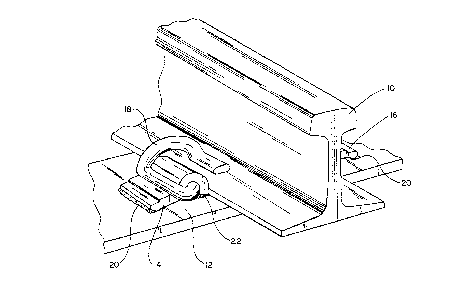
Figurs 1 i~ " 1 y, vlew Or a portlon Or a railway
tnlck nystem r~il ir L ll~t~on which includes the ~ _ ~,.. ' rnil
nnchor assembly Or thiu i.~ o~;
Figure 2 i8 a p~rspective view of n welded prior art rAil
anchor a~is~mbly ~ rltting , L; ~nd
Figure 3 i8 a perspective view Or the welded shoulder
ritting ~ Or th~ rnil anchor A~ . mbly o~ Figur~ 1.

~ DT'--q~ION
Figure l; 1 l Lr._tas a portion of a railway syDtem steel
rail ~10~ which i8 supported by ste~l base plate (12) and
restr~inQd in its support~d position by a ~r - ap~rt p~ir o~
shoulder rittings (14 ~nd 16) which are welded to base plate (12)
and by a pair Or conv-nt;sn-l spring clips of which only one
(spring clip 18) appears in the illustration. Each shoulder
~itting (14 and 16) is welded to base plate (12) by an outer end
wel-' bead (20) and by a rail end wel~ bead (22). Although not
ill~strated in Figure 1, b~e plat~ (12) i8 provided with
multiple -,p~ for the insertion Or conventional f~ t ~
such as bolts or spikes used to secure the base plate to a
conventional support such as a rail tie ~also not shown).
As I;hown in rigure 3, shoulder fitting (14) has a rail
nd portion (24), an outer end portion (26), and a clip
retainer portion (28) vAich extendls intermediate the ritting end


~5~6~i
portions. In the Figure 1 aL- , ~, shoulder fittings (14 and
16) are spacQd apart ~ distance whereby their ~ ' ive rail
~nd ext~rior vertic~l f~ces will be very nearly in abutting
rel~tion to th.~ Qdgen Or th- b-lu-~ Or r~il (10). ~rhus, lt 1~
~ "nt. that thQ I ~ ~.u~ (30) provlded ln the shoulder fltting
rAil ~ end portion tZ4) b.~ oriented so that thc bevel
groovQ for welding which it rorms with the upper surrace o~ base
plate (12) when placQd in po~ition i8 accessible for weld
~ormation from the interior region of ~rcuate clip retainer
portion (28) r~ther th~m rrom th~ ritting ~xterior closest to the
pof~ition Or the rzlil b~e edge. Note th~t in the Figure 2 prior
rt shoulder rittlng rererenced ~8 40, the rnil end portion
u.,~ vu~ (42~ is oriented in a opposite sense relative to the
ritting vertical rail ~I_i t race. (Note also thllt the
u..d~ uL (32) provided ror rorming 1I weld bead groove at the
~h~ r ritting outer end portion (26) 18 oriented in the same
direction in each Or the Flgure 2 and the Figures 1 and 3
shoulder ~itting versions). In the prior art method of weld bead
locetion it become~ r ~~ to grind or machine away that
portion of the weld bead that pro~ ect~; exteriorly beyond the
ritting rail end portion vertical r~il abutment face to permit
proper seating Or the rail upon the rail anchor assembly base
plate. ~o portion o~ a weld (20) requires removal because that
weld is positioned distant from the base o~ rail (10).
Lastly, it should be pointed out that spring clip (18)
ut~ ,' with thQ; v.. I r~il anchor assembly compri~;es no part
Or l:he pregent invention and guch may take any o~ several
dirferent ~orms. ~he orm illustrated in Figure 1 cvLL._t,vl~ds to


21~3g6~7
. ~
the configurAtion Or a spring clip prf~l:ently r-rk--t---l in the
United Statfls by Pandrol Jz~ckgon, Inc. Or Ludington, Mt.~hi~
It is essontially only ~f y that the spring clip-rfJc~living
opening rormed by the upp-lr urracQ of base plate ( 12 ) and thfJ
interior sur~ace o~ welded shoulder fitting clip retainer portion
(28) ha~e a ~ 1 conriguration suitable ror receiving
the cc...~,-3L~ting leg Or thfJ spring clip lr-~ 1 to be driven into
the opening ~or the purpose Or limiting vertical - .. ' Or the
r~il b~s3 with which it . , ..t
r t part sh~pfJI~, rel~tiv~ lzss, -nd ~o~teri~lls other
thaD those dir~l~ 3 in the drawings and detailed description m~y
be utilized in the ~" ' i-~c of our invention without departing
~rom thQ scope or intfJnt Or the claims which rollOw.
We claim as our invention:

Representative Drawing
A single figure which represents the drawing illustrating the invention.
Administrative Status

For a clearer understanding of the status of the application/patent presented on this page, the site Disclaimer , as well as the definitions for Patent , Administrative Status , Maintenance Fee  and Payment History  should be consulted.

Administrative Status

Title Date
Forecasted Issue Date 1999-03-23
(22) Filed 1995-07-25
Examination Requested 1995-10-27
(41) Open to Public Inspection 1996-01-26
(45) Issued 1999-03-23
Expired 2015-07-27

Abandonment History

There is no abandonment history.

Payment History

Fee Type Anniversary Year Due Date Amount Paid Paid Date
Application Fee $0.00 1995-07-25
Registration of a document - section 124 $0.00 1995-10-19
Maintenance Fee - Application - New Act 2 1997-07-25 $100.00 1997-06-09
Maintenance Fee - Application - New Act 3 1998-07-27 $100.00 1998-06-05
Final Fee $300.00 1998-12-03
Maintenance Fee - Patent - New Act 4 1999-07-26 $100.00 1999-06-14
Maintenance Fee - Patent - New Act 5 2000-07-25 $150.00 2000-06-19
Maintenance Fee - Patent - New Act 6 2001-07-25 $150.00 2001-07-19
Maintenance Fee - Patent - New Act 7 2002-07-25 $150.00 2002-07-03
Registration of a document - section 124 $50.00 2002-08-29
Maintenance Fee - Patent - New Act 8 2003-07-25 $150.00 2003-07-03
Registration of a document - section 124 $50.00 2003-12-30
Registration of a document - section 124 $100.00 2004-02-16
Maintenance Fee - Patent - New Act 9 2004-07-26 $200.00 2004-07-19
Maintenance Fee - Patent - New Act 10 2005-07-25 $250.00 2005-06-27
Maintenance Fee - Patent - New Act 11 2006-07-25 $250.00 2006-06-28
Maintenance Fee - Patent - New Act 12 2007-07-25 $250.00 2007-06-26
Maintenance Fee - Patent - New Act 13 2008-07-25 $250.00 2008-06-20
Maintenance Fee - Patent - New Act 14 2009-07-27 $250.00 2009-07-09
Maintenance Fee - Patent - New Act 15 2010-07-26 $450.00 2010-07-08
Maintenance Fee - Patent - New Act 16 2011-07-25 $450.00 2011-07-14
Registration of a document - section 124 $100.00 2012-05-25
Maintenance Fee - Patent - New Act 17 2012-07-25 $450.00 2012-07-12
Maintenance Fee - Patent - New Act 18 2013-07-25 $450.00 2013-07-15
Maintenance Fee - Patent - New Act 19 2014-07-25 $450.00 2014-07-11
Owners on Record

Note: Records showing the ownership history in alphabetical order.

Current Owners on Record
VOESTALPINE NORTRAK INC.
Past Owners on Record
ABC RAIL PRODUCTS CORPORATION
ABC-NACO INC.
CHRISTIANSEN, DUANE B.
MERIDIAN RAIL INFORMATION SYSTEMS CORP.
MERIDIAN RAIL TRACK PRODUCTS CORP.
MERTES, DALE J.
POLLOCK, MARK A.
REMINGTON, JAMES A.
VAE NORTRAK NORTH AMERICA INC.
Past Owners that do not appear in the "Owners on Record" listing will appear in other documentation within the application.
Documents

To view selected files, please enter reCAPTCHA code :


To view images, click a link in the Document Description column. To download the documents, select one or more checkboxes in the first column and then click the "Download Selected in PDF format (Zip Archive)" or the "Download Selected as Single PDF" button.

List of published and non-published patent-specific documents on the CPD .

If you have any difficulty accessing content, you can call the Client Service Centre at 1-866-997-1936 or send them an e-mail at CIPO Client Service Centre.


Document
Description 
Date
(yyyy-mm-dd) 
Number of pages   Size of Image (KB) 
Representative Drawing 1999-03-16 1 16
Claims 1998-09-10 2 74
Cover Page 1999-03-16 1 53
Cover Page 1996-08-06 1 11
Abstract 1996-01-26 1 15
Description 1996-01-26 6 139
Claims 1996-01-26 2 29
Drawings 1996-01-26 1 26
Assignment 2002-08-29 9 286
Assignment 2003-12-30 6 207
Correspondence 1998-12-03 1 34
Prosecution Correspondence 1996-02-23 1 31
Prosecution Correspondence 1995-10-27 1 42
Prosecution Correspondence 1998-06-15 2 48
Examiner Requisition 1998-03-17 2 38
Prosecution Correspondence 1996-07-18 1 32
Prosecution Correspondence 1996-07-18 4 243
Office Letter 1996-04-22 1 57
Office Letter 1995-09-20 1 20
Prosecution Correspondence 1995-07-25 13 453
Assignment 2004-02-16 13 304
Correspondence 2004-02-16 4 126
Correspondence 2004-03-17 1 27
Correspondence 2004-03-22 1 14
Correspondence 2004-03-22 1 17
Fees 2004-07-19 1 29
Assignment 2012-05-25 7 186