Note: Descriptions are shown in the official language in which they were submitted.
WO 94116638 ~ 58 PCT/US93/12493
BONE CAP AND METHOD OF MAKING 8AME
Backqround of the Invention
The present invention relates generally to bone caps and
a method of making orthopedic prosthetics. More specifically,
the present invention relates to a metatarsal, metacarpal or
phalangeal bone cap of the type used to cover a remaining
portion of a bone after surgical removal of a degenerated or
injured joint. The present invention also relates to a method
of forming articles of polytetrafluoroethylene ("PTFE") in
which expanded PTFE ("e-PTFE") is integrally bonded to non-
expanded PTFE ("n-PTFE").
PTFE is a substantially chemically inert, biocompatible
thermoplastic polymer composed of long linear carbon chains
surrounded by fluorine atoms. PTFE is usually molded or
extruded under extremely high pressure and temperatures.
Expanded PTFE comprises a porous microstructure of "nodes" and
"fibrils". The fibers originate from the nodes with the nodes
being generally thicker than the fibrils. The fibril length
is controlled during processing and determines the porosity of
the material.
PTFE is extremely hydrophobic as a result of the high
electronegative charge of its polymer chains. This
electrochemical property renders PTFE less thrombogenic than
other biocompatible implant materials.
Because of its highly non-reactive natural state, it has
been regarded necessary to either derivatize the PTFE by
stripping the fluorine atoms with an etchant to allow chemical
bonding with the underlying carbon-chain backbone of the
polymer or coat the PTFE with another more reactive polymer.
Coating PTFE has typically been done by dipping the PTFE into
liquid polymers which are, themselves, then capable of being
bonded to other materials.
W094/16638 2~1$~S8 PCT~S93112493 ~
In the field of internal biocompatible materials,
however, the use of etchants, adhesives, silicones, latex or
other potentially bioreactive materials is undesirable.
PTFE, both in its expanded and non-expanded states, has been
generally recognized as an ideal material for body implants,
internal prosthetics, tissue grafts, etc. because of its high
degree of biocompatibility and biochemical inertness.
A wide variety of material compositions exist which
employ either e-PTFE or n-PTFE, either alone, in combination
with another material or in combination with each other. For
example, U.S. Patent No. 4,147,824 discloses that it is known
to make a plastic seal by compressing a layer of pure powdered
n-PTFE in a mold, and then placing on top of the formed n-PTFE
layer another layer of sinterable PTFE powder containing a
filler material. The mixture is compressed in a second
pressing and the two-layer material is sintered, after which
the filler material is flushed out forming porosities in the
second layer. U.S. Patent No. 4,283,448 discloses a process
by which articles can be made by edge joining two or more
pieces of e-PTFE by sintering the pieces under pressure to
form the desired article without forming a non-porous seam at
the joint.
U.S. Patent No. 4,892,779 discloses a multilayered
article made of one layer of a non-porous material fusion
bonded, without adhesive, to a layer of microporous material
having a large proportion of water insoluble filler at least
50 percent of which is siliceous. This reference contemplates
that the microporous material may be PTFE, and that the PTFE
may be stretched to increase void volume of the material. The
stretched microporous material is then fusion bonded, without
an extrinsic intervening adhesive, to a substantially
nonporous material. Both the microporous and non-porous
materials have generally opposed major surfaces such as are
characteristic of sheets, films, foils and plates. Fusion
bonding may be made by use of heated rollers, heated bars,
~ WO94/16638 21 ~ ~ ~ S 8 PCT~S9311~93
heated lathes, heated bands, heated wires, flame bonding, RF
sealing, and ultrasonic sealing.
Finally, U.S. Patent No. 5,032,445 discloses a method for
treatment of periodontal disease in which a periodontal
implant is fashioned of a sheet of e-PTFE material having
first and second surfaces. The first surface of the e-PTFE is
permeable to tissue ingrowth, while the second surface is
rendered impermeable to tissue ingrowth in desired areas by
application of heat and pressure only to the areas of
impermeability. This reference discloses that a single sheet
of e-PTFE can be made to have two distinct opposing regions of
tissue permeability and impermeability by application of heat
and pressure to a region on one side of the permeable e-PTFE
sheet, thereby creating a region of non-porous impermeability
on the otherwise permeable e-PTFE sheet.
The method of forming a bond between an article made of
e-PTFE and an article to be formed of n-PTFE, without the use
of an intervening adhesive, appears to be unknown in the art.
Turning now to the bone cap device, the present invention
provides a bone cap having a microporous sheath or tubular
portion and a non-porous end portion. Both the microporous
sheath and the non-porous end portion are made entirely of
PTFE without filler materials, such as carbon fiber or
silicious materials. The sheath is made of e-PTFE to
facilitate tissue ingrowth which anchors the cap to the bone.
The end portion is made of n-PTFE to inhibit bone ingrowth and
function as an articulation surface between the bone cap and
an adjacent bone. The n-PTFE end portion and the e-PTFE
sheath are fused together without the use of intervening
adhesives by the method of the present invention.
A bone cap of the above-described construction appears
unknown in the art. A wide variety of bone caps are known in
the art. For example, U.S. Patent No. 4,007,494 discloses a
-
W094/16~8 PCT~S93/12493
2~S~6S8
bone cap having an inner porous cap and an outer non-porous
cap cover but without a sheath. The porous cap is formed from
a porous polymeric material to enable tissue ingrowth to
anchor the bone cap. The porous cap surrounds all aspects of
an excised bone, including the intramedullary surface. The
non-porous cap cover resides above the outer surface of the
bone cap and restricts tissue ingrowth beyond the porous cap.
The head may also include a stem for insertion into the
medullary canal of the bone. U.S. Patent Nos. 4,362,681 and
4,756,862 disclose a bone cap comprised totally of
bioengineering thermoplastics with select porous areas.
Patent No. 4,756,862 discloses a process for preparing a
sintered bioengineering thermoplastic material. Patent No.
4,362,681 discloses a process for preparing a prosthetic
device, such as a hip joint, which involves sintering a
particulate thermoplastic material onto a load bearing
functional component to provide a porous coating. U.S. Patent
No. 4,129,470 discloses a method for making implants using
PTFE sintered with carbon or graphite fibers. The implant
preferably has a porous structure of carbon or graphite fibers
bonded together by sintered PTFE in a manner that exposes a
maximum amount of fiber surface. U.S. Patent No. 4,351,069
discloses the formation of an implant using a sintering
technique to form a porous coating on the outer surface of the
implant. U.S. Patent No. 5,098,779 discloses an implant made
of porous PTFE with a stiffening agent. The stiffening agent
alters the porosity of the PTFE in order to allow the PTFE to
be shaped by carving.
Various methods have been employed to bind e-PTFE sheets
or films to other substrates or to impregnate e-PTFE sheets or
films with adhesives. For example, U.S. Patent No. 4,531,916
discloses a dental implant having an e-PTFE gingival interface
between a root structure and a cervical segment and the bone,
and U.S. Patent No. 4,304,010 discloses a tubular PTFE
prosthesis having a porous elastomer coating. Patent No.
4,531,916 discloses that e-PTFE interface is either attached
~ W094/16638 ~S~6S8 PCT~S93/~493
to the cervical and root segments by adhesion, compression
between the cervical and root segments or molding the cervical
and root segments of a biocompatible polymer with the e-PTFE
interface in place. Patent No. 4,304,010 discloses a method
for coating a e-PTFE tube with an elastomeric coating. The
elastomeric coating is applied in solution or as a liquid
compound to the outside surface of the PTFE tube. The
elastomer coating is then dried and cross-linked. The porous
e-PTFE tubing and the por~us elastomer coating are bonded to
each other as a result of a part of the elastomer entering the
pore spaces of the PTFE tubing.
Each of the known methods for joining a structure made of
e-PTFE to another structure involve creating a junction
between a formed e-PTFE structure with another formed
structure. The junction may be formed by impregnating an
adhesive into the microporous structure of an e-PTFE sheet and
subsequently adhering another material onto the adhesive-
impregnated e-PTFE, such as a metal film to form a circuit
board, as disclosed in U.S. Patent No. 4,916,017. A junction
may also be formed by wrapping a bundle of e-PTFE fibers
axially along a length of wire, then wrapping the bundle of
fibers with an e-PTFE tape and sintering the entire resulting
structure to meld the fibers and tape into a unitary structure
as disclosed by U.S. Patents No. 5,059,263. Similarly, a
junction can be created between sheets or films of e-PTFE
surrounding a plurality of parallel wires to form a ribbon
cable by sintering compressing the sheets and sintering the e-
PTFE sheets to each other, as disclosed by U.S. Patent No.
4,988,835 and U.S. Patent No. 4,978,813. Edge joining by
sintering adjacent articles made of e-PTFE to create a porous
seam while compressing the e-PTFE articles, is taught by U.S.
Patent No. 4,283,448.
.
Accordingly, methods of binding e-PTFE sheets or films to
other formed structures made of e-PTFE by compression and
sintering is well known. Additionally, the use of adhesives
W094/16~8 PCT~S93/12493
~ 6
to laminate e-PTFE sheets or films to another material, such
as a metal film in a circuit board, is well known. The
creation of a bond between existent e-PTFE structures, such as
sheets or films, is common to each of these known methods.
It is also known that regions on a sheet of e-PTFE may be
made non-porous, or converted to n-PTFE, by application of
heat and pressure to the region to be altered. U.S. Patent
No. 5,032,445 discloses a method to alter a region to make it
impermeable to tissue ingrowth. The method of this patent
entails providing a sheet of e-PTFE having first and second
surfaces. A region of the second surface is made impermeable
to tissue ingrowth by applying plates heated between 300-400
C under pressure to the e-PTFE sheet. Application of heat
causes the e-PTFE region on the second surface to coalesce
into a non-porous condition in intimate contact with the
opposing e-PTFE first surface without the use of adhesives.
A similar method is disclosed by PCT International
Application W0 90/06150. This reference discloses that a
catheter may be made having a porous tip by two different
methods. A first method entails forming a tube of n-PTFE and
expanding an intermediate portion of the tube to create an e-
PTFE region. A second method entails forming a tube of e-
PTFE, covering an intermediate portion of the tube with a
material of low thermal conductivity and sintering the
unprotected regions of the e-PTFE tube.
Another related method is taught by U.S. Patent No.
4,701,362 for forming reinforced through-holes in an e-PTFE
sheet. This patent discloses exposing a sheet of e-PTFE to a
point heat source, such as a laser or heating rods, which
creates holes in the e-PTFE sheet by sintering an annular
collar surrounding the through-hole. The sintered annular
collar is formed of non-porous PTFE.
W094/16638 S~6S8 PCT~S9311~93
Each of these methods entail sintering regions on an
existent e-PTFE structure to convert the sintered regions to
non-porous n-PTFE.
There appear to be no known methods for forming a
structure onto an existent e-PTFE structure. The bone cap of
the present invention is an example of one type of device
capable of manufacture by the method of the present invention.
Those skilled in the art will recognize that the method of the
present invention can be used to form a wide variety of
devices made of either e-PTFE, n-PTFE or a combination
thereof.
Summary of the Invention
The preferred embodiments of the present invention relate
to a bone cap having a tubular section made of porous e-PTFE
and an enclosed end section made of non-porous n-PTFE. The
tubular section is porous to enable tissue ingrowth and
revascularization, while the non-porous end section prevents
bony ingrowth and protects the excised end of the bone.
The method of the present invention provides a method for
making an article of e-PTFE, n-PTFE or a combination thereof,
in which a starting structure, such as a tubular body, is
provided and a second structure, such as an end cap, is
integrally formed onto the starting structure. The method
entails mounting the starting structure onto a mandrel,
filling a mold with powdered, unsintered PTFE, inserting the
mandrel into the mold such that a region of the starting
structure is immersed in the mold, applying positive pressure
to the mandrel, securing the starting structure onto the
mandrel and securing the mold/mandrel assembly together. The
mold/mandrel assembly is mounted in an oven well to expose
only the powdered, unsintered PTFE and the bonding region of
the starting structure to sintering temperatures. The
powdered, unsintered PTFE coalesces with the region of the
WO94/16638 = 21~ ~ 65~ PCT~S93/12493 ~
." ~
starting structure exposed to the unsintered PTFE, thereby
forming a unitary formed structure onto the starting
structure.
Brief DescriPtion of the Drawinqs
FIG. 1 is a perspective view of a bone cap in accordance
with the present invention.
FIG. 2 is a side-elevational cross-sectional view taken
along line 2-2 of FIG. 1.
FIG. 3 is a side-elevational view illustrating the
inventive bone cap surgically attached to an excised bone.
FIG. 4 is a flow diagram representing the method of the
present invention.
FIG. 5 is a side elevational cross-sectional view of a
mold and mandrel assembly employed in making the inventive
bone cap using the inventive method.
FIG. 6 is a side elevational partial cross-sectional view
diagrammatic view illustrating a sintering well in accordance
with the present invention.
FIG. 7 is an enlarged view of region 7 of FIG. 6.
FIG. 8 is a perspective view of a sintering oven for use
in the method of the present invention.
FIG. 9 is a diagrammatic cross-sectional view of a
junction region between n-PTFE and e-PTFE regions of an
article made in accordance with the inventive method.
~ ~V094/1663~ 21$~6s~ PCT~S931~493
Detailed Description of the Preferred Embodiments
Bone caps are implant devices designed to be placed over
distal shafts of the metatarsal or metacarpal bones following
metatarsal or metacarpal head resection. The bone cap implant
provides a smooth surface for articulation against the
proximal phalanx. Bone cap implants are indicated in
degenerative or inflammatory joint disease, dislocation or
subluxation of the lesser metatarso- or metacarpophalangeal
joints, painful joints with limitation of motion, or revision
of previous procedures in the presence of sufficient bone
stock. Bone cap implants are also designed to be placed over
the proximal phalangeal shaft following phalangeal head
resection. The phalangeal bone cap implant provides a smooth
surface for articulation against the middle phalanx.
Phalangeal bone caps are generally employed in patients with
angular deformity, impaired joint function and stability, pain
and destroyed articular surfaces; all indications commonly
found in the proximal interphalangeal joints in flexion
contractures of the toes.
FIGS. 1-3 in the accompanying drawings illustrate bone
cap 10 of the present invention. Bone cap 10 may be used to
truncate the metatarsus, metacarpus, or the phalangeal bones
of both the hand or foot, with the principal difference simply
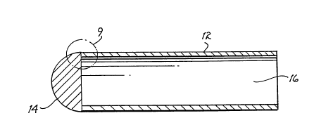
being the size of the bone cap 10. Bone cap lo consists of a
tubular sleeve 12 and an end cap 14 which encloses one end of
the tubular sleeve 12. A second end of the tubular sleeve 12
is open to allow access to a lumen 16.
As illustrated in FIG. 3, bone cap 10 is surgically
fitted onto either the metatarsal bone 18 or the phalangeal
bone 20. Bone cap 10 is fitted onto the resected metatarsal
head 19 or the phalangeal head 21 to provide an articulation
surface for the metatarso-phalangeal joint 22 or the
interphalangeal joint 23, respectively.
W094116638 ~ 21S 4658 PCT~S93/12493 ~
~ or purposes of illustration reference will hereinafter
be made only to the metatarsal bone 18. Bone cap 10 is
affixed onto the distal shaft of the metatarsal bone 18. The
resected metatarsal head 19 is placed into the lumen 16 and
the bone cap 10 is axially positioned onto the distal shaft of
the metatarsal bone 18. The resected head 19 should rest
adjacent or in close proximity to the inside surface of end
cap 14.
The surgical implant procedure can be performed on an
outpatient basis using intravenous sedation and local
anesthesia. A dorsilinear incision is made directly over the
metatarsophalangeal joint, extending from approximately the
distal third of the shaft of the metatarsal to a point midway
along the shaft of the proximal phalanx. The incision is
deepened by both sharp and blunt dissection and bleeders are
coagulated as encountered. The subcutaneous tendons and
neurovascular bundles are retracted out of the operative site.
The dorsal capsule of the metatarsophalangeal joint is entered
by a linear incision made at a point just proximal to the
anatomical neck and distally to the metatarsophalangeal joint.
The metatarsal head is dissected free of its attachments and
a transverse osteotomy is made in the area of the anatomical
neck. The remaining portion of the bone is smoothed with a
fine diamond rasp. Care should be exercised to minimize the
disruption to the periosteum surrounding the distal
metatarsal. The area is preferably irrigated with an
antibiotic irrigating solution to remove osseous debris. The
soft tissue is then gently moved proximally from the distal
portion of the metatarsal shaft. A sizer is placed over the
distal aspect of the prepared metatarsal shaft to check for
fit. The appropriate size bone cap implant 10 is then
manipulated into position such that the tubular sleeve 12
resides over the bone shaft and the interior surface of the
end cap 14 abuts adjacent to, or in close proximity to, the
excised metatarsal shaft. If desired, the implant may be
secured by sutures passing through the proximal end of the
W~94/16638 6$8
tubular sleeve 12 and tacked to adjacent soft tissue. The
surrounding capsular structure and wound is closed using
appropriate sutures.
Bone cap 10 is preferably made of a porous biocompatible
material forming the tubular sleeve 12 and a non-porous
biocompatible material forming end cap 14. The bone cap 10 is
preferably made by bonding the tubular sleeve 12 to the end
cap 14 without additional copolymers, additives, or adhesives,
thereby eliminating the possibility of leaching potentially
bioreactive substances. E-PTFE is preferably used for the
tubular sleeve 12, while n-PTFE is preferably used for the end
cap 14. The use of PTFE for the joint implant of the present
invention is advantageous in that it provides a chemically
inert and biocompatible implant which has a high tensile
strength and a low coefficient of friction. The porosities
formed by the node and fibril structure of e-PT~E which
comprises the tubular sleeve 12 promote tissue incorporation
and revascularization, and implant anchoring. The non-porous
n-PTFE acts to inhibit tissue ingrowth into the joint region.
After implantation of the bone cap implant 10, tissue
ingrowth will occur into the node and fibril structure of the
e-PTFE of the tubular sleeve 12. The end cap 14, being non-
porous, will prevent tissue ingrowth into the
metatarsophalangeal joint.
Clinical ExamPles
A total of fifteen bone caps were implanted in five
patients in accordance with the present invention over a three
month period. Patients were selected based on adequate
vascular status, presence of fibro-osseous unions (joint
fusions), progressive joint deformity and the presence of
intolerable pain with little or no peripheral inter-phalangeal
joint (PIPJ) range of motion available. The structural joint
changes of those patients selected no longer responded to
W094/16638 ~ PCT~S93/12493
2~'465'8
12
conservative treatment. In addition, those patients with
hammertoes often exhibited PIPJ subluxations/dislocations,
often with varus deformities. The metatarsal bone caps were
indicated in forefoot reconstruction procedures, degenerative
or inflammatory metatarsophalangeal joint (MPJ) diseases,
lesser MPJ subluxations and dislocations, painful prominent
metatarsal heads, or painful arthritic joint disease with
limited range of motion. Following surgery, patients were
evaluated at one, two, four and twelve week intervals for
signs of infection, edema, pain, implant failure and bony
resorption. All patients received preoperative prophylactic
Ancef W. All surgeries were performed on an outpatient basis
under IV sedation and local anesthesia. The joint implant of
the present invention was implanted in patients according to
the surgical procedure previously described.
The clinical trials showed patients with a significant
post-operative increase in functional metatarsal parabola,
with a shorter post-operative recovery period and an earlier
return to wearing normal footwear. The tests further
demonstrated minimal to non-existent post-operative
fibrositis, foreign body reaction, infection, and dislocation.
Patients also exhibited limited to non-existent post-operative
edema or pain.
The method of the present invention is illustrated with
reference to FIGS 4-8 of the accompanying drawings. For
purposes of illustration, the inventive method will be
described with reference to making the inventive bone cap lO,
in which an end plug, i.e., the end cap 14, is fused to an end
of an tube made of e-PTFE, i . e ., tubular sleeve 12. Those
skilled in the art should understand and appreciate, however,
that the method may be used to make other structures. The
method may also be used, for example, to form a hard sleeve
made of n-PTFE onto the end of an tube made of e-PTFE to
create a machinable surface or to form a molded structure of
n-PTFE onto a sheet or film of e-PTFE.
W094/16638 I S~ PCT~593/1~93
FIG. 4 sets forth process steps of the inventive method
used to make bone cap lO and illustrate application of the
method to form a PTFE structure onto an existent PTFE
structure. As illustrated in FIGS. 5 and 6, there is provided
a mold assembly 40 and a heater 50. Mold assembly 40 consists
of a mold 42 having an interior mold cavity configured to form
a desired object. In accordance with the method to make the
inventive bone cap lO, mold cavity 43 is formed as a concave-
ended cylindrical cavity. The mold 42 is configured to
concentrate thermal energy in a lower aspect 44 of mold 42.
Concentration of thermal energy in the lower aspect 44 is
important because the unsintered PTFE will be placed in the
lower aspect 44 of mold 42, while the sintered e-PTFE will
substantially reside in other areas of cavity 43. In this
manner, the sintered e-PTFE is distant from the concentration
of thermal energy to minimize coalescing of e-PTFE to the n-
PTFE state.
A mandrel 46 and push rod 48 are provided. Mandrel 46
serves as a support for the existent structure onto which the
structure to be formed is molded. The push rod 48 facilitates
application of positive pressure to a powdered, unsintered
body of n-PTFE deposited into the mold cavity 43. Applying
compressive force is needed to create a formed body and ensure
proper coalescence of both the formed body and the area
between the formed body and the e-PTFE existent structure when
sintered.
A sintering oven 50 is illustrated in FIGS 6-8. For high
volume production it is preferable to simultaneously fabricate
multiple articles. Those skilled in the art will understand
that multi-cavity molds 42, mold assemblies 40 and sintering
ovens 50 facilitates process scale-up and increases device
throughput. Sintering oven 50 preferably consists of a
plurality of heating wells 54 formed as a planar body 42 made
of a thermally conductive material, such aluminum. A
thermally non-conductive material is provided as an insulating
-
WO94/16638 2¦$ 4~S8 PCT~S93/12493
14
surface member 53. Insulating surface member 53 should be of
sufficient thickness to allow the mold assembly 40 to seat
with only the lower region 44 of the mold 42 being exposed to
the heating coils 56. The insulating surface member thermally
insulates substantially the entire length of the mold assembly
42, exposing only a bottom portion of the mold 44 and mold
cavity 43 to heat. In this manner the thermal energy is
concentrated in an area to be exposed to sintering heat.
Each of the heating wells 54 is formed into both the
insulating surface member 53 and the conductive planar body
52. Each heating well 54 accepts a mold 42 therein and
exposes the lower region 44 of the mold 42 to a concentrated
heat source. In accordance with the best mode of the present
invention there is disclosed a resistive heating coil 56
surrounding each of the plurality of heating wells 54.
Heating coil 56 is connected, via wires 58, to a voltage
source 60 which provides electricity to the resistive heating
coils 56.
It is preferable to provide a digital temperature gauge
64 and thermocouple 62 in thermal or electrical connection
with the heating coils 54 or heating wells 56. The provision
of the temperature gauge 64 permits temperature readouts to
ensure that adequate sintering temperatures are reached in the
heating well 54 to sinter the n-PTFE to the e-PTFE sleeve.
The presence of a thermocouple 62 is desirable. Thermocouple
62 can act as a controller for the voltage source 60 to
increase or decrease voltage output to the resistive coils 56
in order to reach a pre-set temperature point. Additionally,
thermocouple 62 can be used to output a control signal to
automated process controls (not shown) to actuate mechanical
loading or unloading of the mold assemblies 40 into the
heating wells 54.
Finally, it is contemplated that cooling means 66, such
as cooling coils, can be provided in the insulating member 53
~ W094/16638 ~ PCT~S93/12493
-- 21s~
adjacent to the mold assembly 40. Cooling means 66 may be
linked to a heat exchanger (not shown) to provide a recycling
source of a cooling fluid medium. Providing cooling means 66
facilitates formation of a distinct thermal boundary in the
mold between the e-PTFE sleeve region and the n-PTFE end cap
region to be sintered. Protecting the e-PTFE region from heat
generated by the heating coils 56 further guards against
contraction of the porous e-PTFE to non-porous n-PTFE. The
cooling means may, for example, consist of tubular members
which act as a fluid conduit to conduct a recycling cooling
fluid to and from the heat exchanger.
The inventive bone cap 10 is preferably made in
accordance with the process 30 illustrated in FIG. 4. A
tubular e-PTFE sleeve is selected 31 and then fitted onto
cylindrical mandrel 32. The tubular sleeve is adjusted 33
such that a first end extends beyond a first end of the
mandrel about 0.125 inches, this extension is then inverted
into the luminal opening in the mandrel. The second end of
the tubular sleeve is secured onto a second end of the mandrel
by use of a wire tie, clip or other fastening means. A first
body of powdered, unsintered PTFE, of predetermined volume or
weight, is poured 34 into the mold cavity. The first inverted
end of the tubular member on the mandrel is then inserted into
the mold cavity 35. The tubular sleeve and mandrel assembly
is pressed into the mold and into the first body of powdered,
unsintered PTFE residing in the mold cavity. A second body of
powdered unsintered PTFE, of predetermined volume or weight,
is poured into the mold cavity through the luminal opening of
the mandrel 36. A push rod is inserted through the lumen of
the mandrel and positive pressure 37 is applied to the push
rod and mandrel to compress the PTFE into a solid plug with
the e-PTFE tubular sleeve in intimate contact with the solid
plug of unsintered PTFE. The mold assembly is transferred to
the sintering oven and placed into a heating well. The mold
is exposed to sintering heat 38 which sinters the n-PTFE plug
to the e-PTFE sleeve, causing the n-PTFE plug and the
W094/16~8 2 1 S ~ 6 5 ~ PCT~S93/12493 ~
16
contacted region of the e-PTFE sleeve to coalesce into a
unitary sintered structure. After the mold assembly reaches
sintering temperature, the mold assembly is removed from the
sintering oven and cooled 39. After cooling the push rod and
mandrel are removed, and the resulting bone cap implant
removed from the mandrel, inspected and trimmed a desired
length.
EXAMPLE 1
A mold was formed by drilling a 1.0 inch aluminum rod
concentrically along its longitudinal axis with a 0.375 inch
drill to a depth of 0.50 inch. A mandrel was formed by
machining a 2.25 inch long aluminum tube to a 0.28 inch
outside diameter and a 0.215 inside diameter. A solid
stainless steel rod was machined to 0.187 inches to form a
push rod. A 0.50 inch hole was drilled into a 4" x 6" x
0.250" aluminum sheet to provide a heat sink away from the
mold. A standard propane torch was used to heat the
protruding mold.
Approximately 0.5 teaspoon of unsintered, powdered PTFE
resin was pored into the mold cavity. A piece of e-PTFE tube
was fitted over the outer diameter of the aluminum mandrel.
A first end of the e-PTFE tube was adjusted to extend beyond
a first end of the mandrel by 0.125", then inverted into the
lumen of the mandrel. A second end of the e-PTFE tube was
secured to the outer diameter of the aluminum mandrel by tying
with brass wire about the circumference of the e-PTFE tube.
The first end of the e-PTFE tube and the first end of the
mandrel were pressed into the mold and into the powdered,
unsintered PTFE in the mold cavity. A second small amount,
approximately 0.125 teaspoon, of unsintered, powdered PTFE was
introduced into the lumen of the mandrel and the steel push
rod was inserted into the lumen of the mandrel. Positive
pressure was applied to the push rod and the mandrel to form
a solid plug of the powdered, unsintered PTFE about the first
W094/16~8 ~ ~ ~ PCT~593/~93
end of the e-PTFE sleeve and mandrel. The mold assembly was
placed in the 0.50 inch hole in the aluminum plate with about
0.125 inches of the mold protruding through the bottom of the
aluminum plate. A propane torch was used to heat the bottom
surface of the mold, with the blue tip of the flame held at
the bottom of the mold for sixty seconds. The mold assembly
was removed from the aluminum plate and quenched in room
temperature water. The mold assembly was disassembled and the
tubular sleeve removed from the mandrel The PTFE plug was
found to be hard and sintered. The e-PTFE connected to the
end plug was heat damaged and contained severe radial fissures
along the tube length. However, it appeared that the n-PTFE
and the e-PTFE had coalesced together forming a unitary
structure. The test was repeated with heating for 50 seconds,
with the same heat damage evident in the finished product.
The foregoing is a general description of the inventive
method for forming a solid body of n-PTFE onto an existent
structure made of e-PTFE and is representative of the best
mode known to the inventor. Those skilled in the art should
recognize that description of the inventive method with
reference to a process for making the inventive bone cap is
for illustrative purposes and is not intended to limit the
scope or application of the inventive method. Rather, the
method may be used to form any type or desired configuration
of n-PTFE onto an existent structure of e-PTFE.
EXAMPLE 2
The same procedures were employed as in Example 1, except
that the mold was made of brass. After heating the bottom of
the brass mold for 50 seconds, the resultant tube and end plug
showed no sign of heat damage. The resulting structure
evidenced coalescence of the n-PTFE into an end plug
integrally joined to the e-PTFE tube.
W094/16~8 ~ PCT~S93/12493
' '21~6S~ --
18
EXAMPLE 3
The same procedures were employed as in Example 2, except
that a small resistance oven was built using an inverted cone
design of coils capable of 1 amp per volt. The inverted coil
structure was set in an insulator and held in position by a
refractory. A variac controller was set to output 8 volts
yielding an oven bottom temperature of 1051 C with the heat
extremely localized at the oven entrance. The mold assembly
was placed in the oven entrance and heated until the n-PTFE
plug reached sintering temperature. Dwell time was a function
of the size of the mold. Plug temperature was measured with
a hand held FLUKE thermometer and a 12" probe thermocouple.
It was found that the sintering oven used with the brass mold,
consistently yielded a well coalesced end plug of sintered n-
PTFE integrally formed onto the end of the e-PTFE sleeve.
Table 1, below, sets forth the preferred dimensions of a
lesser metatarsal bone cap implant in accordance with the
present invention.
TABLE 1
Size Sleeve Length Inside
Thickness (mm) Diameter
(mm) (mm)
0.305 19.1 6.4
0.305 19.1 7.6
0.305 19.1 8.6
0.305 19.1 9.3
0.305 19.1 10.2
0.305 19.1 11.0
Table 2, below sets forth the preferred outside
dimensions for the mandrel and the push rod and the inside
diameter of the mold cavity, used to make bone cap implant
sizes 10-60.
W094/16~8 .,21 $~ ~ PCT~S93/12493
19
TABLE 2
Size Mandrel Push rod Mold Cavity
(mm) (mm) (mm)
6.6 5.6 7.s
7.7 6.9 8.6
5 30 8.9 8.1 9.8
9.7 8.9 10.6
10.5 9.7 11.4
11.8 11.0 12.7
It is preferable to have a radius on the end of the push
rod to facilitate compaction of the powdered, unsintered PTFE
into the bottom of the mold cavity. For the push rods
identified in Table 2, the radius of the push rod end was
0.0625 chord. In accordance with the best mode known to the
inventor for making the mold assembly, the mold cavity is made
of brass or a brass/stainless steel alloy having an interior
finish of 8 of better. Both the push rod and the mandrel are
preferably made of 300 series stainless steel having a finish
of 32 or better. It has been found that the finished bone cap
implant has a tendency to adhere to the mold cavity if the
mold cavity is made of stainless steel or chromium.
The foregoing description is provided to delineate the
best mode known to the inventors for forming the inventive
bone cap with the inventive process. Those skilled in the art
should understand that the foregoing is illustrative in nature
and is not intended to limit the scope or application of the
inventive method to the manufacture of bone cap implants.
WO94/16638 ;21S 4SS8 PCT~S93/12493 ~
.;;
Rather, the reference to the bone cap structure is provided
for purposes of example only. It is intended that various
structure configuration may be formed onto an existent
structure using the method of the present invention in which
an existent structure serves as a matrix for forming another
structure therewith. Additionally, variations in mold cavity
configuration, mandrel or die configuration, materials,
temperature, pressure and time conditions may be made and
still fit within the intended scope of the inventive process.
While the preferred embodiment of the invention has been
shown and described, it will be apparent to those skilled in
the art that various changes and modifications may be made
without departing from the true spirit and scope of the
present invention. For that reason, the scope of the present
invention is set forth in the following claims.