Note: Descriptions are shown in the official language in which they were submitted.
2ls4ssa
~ WO94/18~2 PCT~S94/01361
HAND-HELD DUAL TECHNOLOGY
IDENTIFICATION TAG READING HEAD
5BACKGROUND OF THE INVENTION
The present invention relates to a hand-held reading
head for reading coded identification tags. More
specifically, the present invention relates to a hand-
held reading head for reading identification tags
attached to an object, which tags are either of the bar
code type or-of the radio frequency signal type.
It is well known to place identifying tags on __
objects so that the objects can be identified for various
purposes. Such identification tags may be, for example,
of the bar code type when the bar code is scanned by a
light source, in particular a laser like source, and the
varying intensity of the light reflected from the bar
code tag is then detected to provide a signal indicative
of the bar code. This identification si~nal is commonly
fed to a data receiver or host computer to identify the
object and/or take some further action. In a similar
manner, a radio frequency identification tag may be fixed
to an object with the tag normally being of a passive
nature which, in response to an interrogating signal,
emits a radio frequency signal which is coded to identify
the object. In either case, the identification code may
a code which is unique to the specific object and/or for
example, may indicate a particular owner for a group of
such objects. In another example of the latter type
situation which is of particular importance, the
identifying tags may be affixed to garments or textile
objects such as towels or linens in a commercial cleaning
establishment so that the textile articles can be
separated and identified as to the owner following
washing or dry cleaning.
At the present time, both bar code type tags and,
more recently and in increasing numbers, radio frequency
_ W094/18642 21~ 8 0 PCT~S94101361
identification tags are being affixed to such textile
type articles. However, the readers presently available
can only read either bar code or the radio frequency
identifying signal. Thus, if articles containing the two
different types of tags are intermingled and
simultaneously processed, and subsequently are to be
identified, this requires two different types of readers,
and in particular hand-held readers. Such a procedure is
obviously time consuming and costly.
It is therefore the object of the present invention
to overcome the above stated problem regarding the two
different types of readers which may be required.
SUMMARY OF THE INVENTION
The above object generally is achieved according to
the present invention by a hand-held dual technology code
reading head which comprises: a hand-held housing having
a light transmissive window at one end thereof; an
actuatable bar code reader disposed in the housing and
including a light source for producing a beam of light
directed along a path to exit the housing via the window
toward a bar-code taq, scanning means for scanning the
light beam along a scan line across the bar code tag and
a light sensor for detecting the intensity of light from
the light beam reflected from a bar code and for
producing an electrical signal corresponding thereto; an
actuatable radio frequency tag reader for producing a
radio frequency signal of a first frequency for
energizing a radio frequency identification tag and for
detecting a radio frequency identifying signal of a
second frequency produced by an energized radio frequency
tag and for producing a corresponding output signal, with
the radio frequency tag reader being disposed in the
housing and including a coil which is mounted within the
housing at the one end of the housing containing the
.~
_ ~094118642 215 ~ ~ ~ D PCT~S94/01361
window so as to avoid the light path and circuit means
connected to the coil for producing the corresponding
output signal; and means, which are manually actuatable
by a user of the reading head, for selectively actuating
one of the bar code reader and the radio frequency tag
reader.
According to a further feature of the invention, the
means for selectively actuating comprises a switch
arrangement positioned on the housing for actuation by a
single finger of a user, and preferably is a normally OFF
three position trigger-like switch.
According to the preferred embodiment of the
invention, the hand-held dual technology reading head
further comprises further circuit means for converting
the output signal from the radio frequency reader to a
format corresponding to that of the output signal from
the bar-code reader, and the reading head is provided
with a common output for the output signals from the bar-
code reader and from the further circuit means.
BRIEF DESCRIPTION OF THE DRAWINGS
Figure l is a schematic cross-sectional view of a
handheld reading head according to the invention which is
capable of reading both bar coded tags and radio
frequency identification tags.
Figure 2 is a isometric view of a hand-held reading
head according to the invention.
Figures 3a to 3f show different orientations and
arrangements of the coil for the radio frequency
identification tag reader in the dual reading head
according to the invention.
Figure 4 is a schematic block diagram of the circuit
of the preferred embodiment of the reading head according
to the invention.
_ WO94/18642 215 ~ ~ 3 PCT~S94101361
DETAILED DESCRIPTION OF THE PREFERRED EMBODIMEN~S
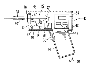
Referring now to Figures l and 2, there is shown a
reading head according to the invention which can be
utilized to selectively read either a bar code tag or a
radio frequency identification tag. As shown in the
figures, the head includes a generally pistol-shaped
housing l0 including an elongated portion 12 and a handle
portion 14 extending transverse to the elongated portion
12. One end surface 15 of the elongated portion 12 is
provided with a light transmissive window 16.
In order to read a bar code tag, a known bar code
reader is disposed within the housing l0. This bar code
reader is of conventional design and, for example, may
include a light source 18, for example a laser diode, for
producing a beam of light which as shown is directed onto
a partially silvered mirror 20 which directs the light
through a suitable culminating and focussing lens 22 onto
an oscillating mirror 24 attached to a scanning motor 26.
The light beam reflected from the oscillating mirror 24
leaves the housing l0 via the window 16 to form an
outgoing light beam 28. This beam 28 is directed toward
a bar code tag and scanned along same in a direction 29
as shown in ~igure 2 and the light 30 reflected from a
bar code tag re-enters the housing l0 via the window 16
and is detected by a detector 32 to provide an output
signal corresponding to the change in intensity of the
reflected beam 30 caused by the scan across the bar code
tag. The analog signal at the output of the detector 32
is fed to a circuit 34 which, in a known manner, converts
the analog output signal of the detector 32 to a digital
signal corresponding to the identifying signal
represented by the bar code which has been read. This
signal is then fed to a host computer or data receiver
via a cable 36 for processing of the data represented by
the identifying signal.
0 94/18642 ~15 ~ 8 $ O PCTIUS94/01361
The electric power for operating the bar code reader
thus far described may be either a battery contained
within the handle portion 14 or may be received via the
cable 36. Actuation of the motor 26, the light source 18
and the remainder of the circuitry of the code reader is
controlled by a trigger-like switch 38 mounted in the
housing 10. A bar code reader operating in the manner
thus far described is known in the art and may, for
example, be a reader of the type disclosed for example in
U.S. Patent No. 4,806,742 or U.S. Patent No. 5,157,687.
In order to be able to selectively read a radio
frequency identifying tag, a radio frequency tag reader
is likewise disposed and mounted in the housing 10. Such
a radio frequency (RF) reader generally includes a coil
40 which is mounted in the housing adjacent the end 15
containing the window 16 and positioned so that it will
not interfere with the scanned light beam exiting the
window 16. This coil 40 is connected to a circuit 42
which is likewise mounted within the housing 10, and
which in a known manner, when actuated, causes the
generation of a radio frequency field around the end 15
of the housing containing the window 16 so that the gun-
like housing 10 may likewise be pointed at a radio
frequency identification tag so as to couple the field to
the tag. In a known manner, the reader for a radio
frequency tag or transponder normally generates an
interrogating signal of a first frequency which is
coupled to the tag via the coil 40 to energize the tag
and cause same to produce a radio frequency identifying
signal of a second different frequency which is then
detected by the coil 40 and fed to the circuit 42 for
processing. Radio frequency identification tags and
readers of this general type are well known, and may for
example be of the type disclosed in commonly assigned
U. S . Patent No . 5, 099, 227 (but utilizing only magnetic
W094/18642 21 5 4 8 8 0 PCT~S94/01361
-
coupling) whereas the reader circuitry may generally be
of the type sold by the Assignee, Indala Corporation,
under the Trademark "RAPID ID", for example a reader
model MHK-103.
In order to establish the desired radio frequency
field for interrogation of the tag and receipt of the
identifying signal from the tag or transponder, the coil
40 for the radio frequency tag reader may be placed in
any number of orientations so long as neither it nor the
circuitry connected thereto is located in the housing 10
so as to obstruct the window 16 and/or the scan of the
laser beam by the mirror 24. Various satisfactory
orientations for the coil or antenna for the radio
frequency reader are shown in Figures 3a to 3f. As shown
in Figure 3a, the coil 40 is entirely on the end surface
15 of the elongated portion 12 of the housing 10 which
contains the window 16. Thus the coil 40 effectively
surrounds the window 16 (as can be seen in Figure 1), to
produce a field in front of the housing 10. With the
arrangement of Figure 3b, the coil 40 extends both on the
end surface 15 of the housing as well as on the upper
surface 44 of the housing portion 12, to produce the
radio frequency field both in front of and on top of the
housing 10. According to Figure 3c, the coil 40 extends
on the front end surface 15 and on the bottom surface 46
of the housing portion 12 to produce an RF field in front
of and below the housing 10. As shown in Figure 3d the
coil may extend from the end surface 15 around each of
the side surfaces 48 or over both the top and bottom
surfaces 44 and 46 as shown in Figure 3f. In each of
Figures 3a to 3d and 3f it is understood that the portion
of the radio frequency coil 40 on the end surface 15 does
not extend over the window 16, or at least does not
obstruct the scan of the light beam 28 exiting the
housing 10 or the reflected light 30 re-entering the
_ WO94/18~2 215 4 8 8 0 PCT~S94/01361
housing lO. Instead of the flat coil-type an~ennas 40
shown in Figures 3a to 3d and 3f (even though the flat
coils are bent around the side and/or upper and/or lower
surfaces), the necessary RF field may be produced by a
coil 40' wound on a ferrite core 41 as shown in Figure
3e. In such case, the core 41 preferably extends
transverse to the end surface 15 containing the window
16, but again must be positioned so that it does not
physically obstruct the scanned light beam in the window
16.
Turning now to Figure 4, there is shown the block
circuit diagram for the dual hand-held reader as shown in
Figures l and 2. As can be seen, the digital output from
the bar code reader 50 is fed via the output cable 36 to
the data receiver or host computer 51. The digital
output signal from the radio frequency tag reader 52 is
likewise fed to this data receiver or computer 51.
However, preferably as shown, the digital output signal
from the radio frequency reader 52 is first fed to a
receiver or microprocessor 54 (which may likewise include
a driver circuit) wherein the output signal from the
radio frequency reader 52 is converted in a well known
and conventional manner, to a digital signal of the same
form and format as the output signal from the bar code
reader 50. The output signal from this unit 54 is then
connected to the output cable 36 which is connected to
the data receiver 51. In this way, the output signal
from the dual reading head can be fed to a single input
port of the data receiver 51 which will then process the
data fed in without regard to which of the two readers 50
or 52 was actually used to read the respective tag.
To assure that data from only one of the readers 50
and 52 is being fed to the receiver 51 at any given time,
and to enable the selective reading by a user of either a
bar code tag or a radio frequency identification tag
W094/18642 215 4 8 8 0 PCT~S94/01361
(transponder), the trigger 38 (Figure 1) is part of a
three position switch 56 for control of the supply of dc
power from the dc power source 58 (e.g. a battery) to the
respective readers 50 and 52. As indicated, for this
purpose, the trigger 38 controls the switch 56 so that it
is normally engaged, for example by spring housing with
the open contact 56a (whereby neither of the readers 50
and 52 is energized or activated), and which can be
depressed to connect the source 58 to the contacts 56b or
56c to selectively supply power to the bar code reader 50
or the radio frequency reader 52, respectively. It
should be noted that although a three position trigger-
type switch as shown is preferred, the switch for
controlling the selective activation of the reader 50 or
the reader 52 may be any other type of switch which
performs this purpose, for example a switch which is
normally in a center OFF position, or even two separate
push button switches for the respective readers 50 and
52. The important criterion for such control is that the
user, when gripping the dual technology reading head, for
example be handle 14, should be able preferably to
control the selective activation of the respective
readers by movement of a single finger.
It should further be noted that the power source or
battery 58, may be within the housing 10 or, if desired,
the power source can be located at the data receiver 51,
whereby the power would be supplied to the housing 10 by
an additional conductor or conductors. Moreover,
although the connection between the hand-held reader and
the data receiver 51 is preferably via the common output
or conductor cable 36, it would be possible to provide an
RF transmitter in the housing 10 to transmit the output
data signal from the dual reading head to a remotely
located data receiver 51 via a radio frequency link at a
frequency substantially different than that used by the
~94/18642 215 4 8 8 0 - PCT~S94/01361
radio frequency reader 52 so as not to cause any
interference.
The invention now being fully described, it will be
apparent to one of ordinary skill in the art that any
changes and modifications can be made thereto without
departing from the spirit or scope of the invention as
set forth herein.